Introduction to Equipment
Specifications
Start Using the Equipment
Initialization
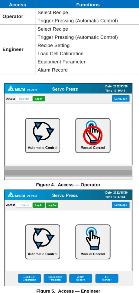
Access
Other Items on the Main Screen
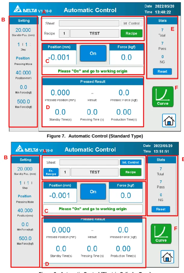
Automatic Control
Introduction
In the automatic control mode, when the press action is activated, the servo press will perform the press according to the recipe parameters set by the user. Under the [Engineering] access, in addition to changing the recipe group, you can also set the recipe's internal parameters. When a recipe is selected, the recipe setting parameters will be loaded into the servo press.
The main parameters of the pressing will be displayed here, including standby position, step, mode, pressing position/distance, pressing force and maximum limit value, etc. However, please make sure that the spindle is in the [Working Origin] position, it does not affect the replacement of the pressed subject. Position] and [Force] are the real-time values of the current servo pressure, while the bottom status bar shows the current operating status of the machine in text.
After each press is completed, the actual [Press Position] and [Press Force] of the press will be displayed, and the maximum and minimum limit values of the position and force are compared according to the mode. This is a record of the total production volume based on a comparison with the maximum and minimum limit values, as well as a record of the number of [OK] and [NG] products.
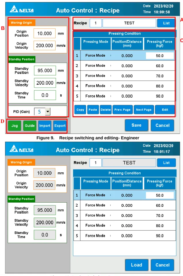
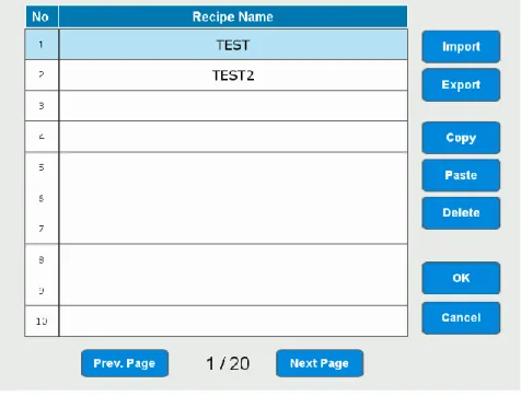
Recipe Switching and Editing
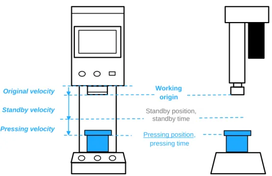
In the [Operator] access a recipe selection can be made based on the assigned number and [List]. can be opened for a quick overview of the recipes. If necessary, it can be set to a position lower than the mechanical origin of the machine, reducing the distance and time of no-load movement during pressing. This is the speed at which the spindle moves from the mechanical origin to the [Work Origin] and returns to the [Work Origin] after the pressing is completed.
A higher velocity value can be set within a reasonable range to reduce the time of no-load movement. This is the end position of high-speed free movement from the [Working Origin] when pressed. It is recommended to set it as close as possible to the printed workpiece while not touching the workpiece, so as to increase the distance of the high-speed part and reduce the low-speed printing part time.
The speed of this no-load section can be increased, within a reasonable range, to reduce overall press time. When used in certain processes, punch must wait for that process to complete before printing can be executed.
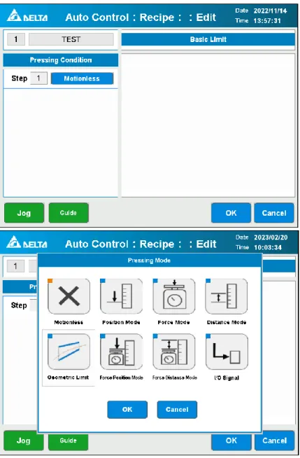
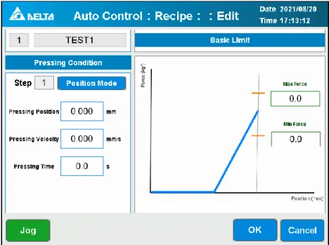
Pressing Condition Edit and Pressing Mode
- Motionless
- Position Mode
- Force Mode
- Distance Mode
- Force Position Mode
- Force Distance Mode
- I/O Signal
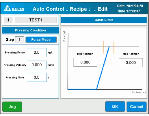
Printing conditions: In position mode, the spindle will print to the [Printing Position] at the [Printing Speed], and after waiting for the [Printing Time], perform the next step or return to the [Work Origin]. Force], the workpiece will be considered NG and the spindle will return to the [Working Origin]. After the spindle reaches the [Press Position], the servo press will check if the force value is within the range of [Max.
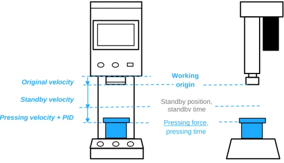
Pressing conditions: In force mode, the spindle will press down at [Pressing Speed] until it reaches [Pressing Force] according to the PID setting speed after hitting the workpiece, and wait for [Pressing Time], then perform the next step or return to [Work origin]. If [Pressing Force] is not reached during the process, the spindle will move to [Max. Position], the workpiece will be evaluated as NG and the spindle will return to [Working Origin].
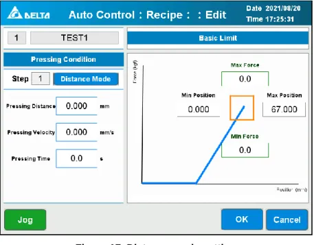
Pressing conditions: In force position mode, the spindle will press down to [Pressing Force] and keep moving to [Pressing Position] at PID speed according to [Pressing Speed] and wait for [Pressing Time]. to perform the next step or return to [Work Origin]. Pressing conditions: In force distance mode, the spindle will press down at [Pressing Force] and continue to move at [Pressing Distance] at PID speed according to [Pressing Speed] and wait for [Pressing Time]. to perform the next step and return to [Work Origin].
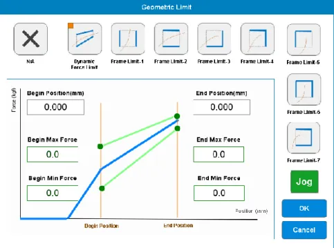
Geometric Limit
The minimum and maximum force at the start and end position must also be set. The servo press will connect the start and end point and generate the upper and lower straight limit line. If the pressure curve is outside the limit, the servo press will judge NG.
It only requires setting four parameters and also providing multiple types, which not only provide the force limit but also the position limit.
Manual Control
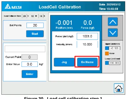
Load Cell Calibration
Calibration Process
Please press the press shaft to the specified external load force of the calibration point using the [Manual Control] module on the right (refer to the appendix). The calibration status will show [Calibration Complete], please select [Go Home] and remove the load cell calibration instrument to exit the calibration program.
Device Parameters
- Basic Settings
- Pressing Counter
- PID Gear Setting
- Others
Soft limit The soft limit is set at the factory based on the upper and lower positions of the Z axis, please do not change it if it is not necessary. This function records the number of presses, and an upper limit can be set for the number of presses. When the number of presses reaches the [Pressed Amount Limit] set by the user, a calibration reminder window will appear.
In force mode, during the pressing process, the [Pressing Velocity] and [Pressing Force] in the recipe are used as references used to calculate the real-time Pressing Velocity with PID. Under most printing conditions, adjusting the [Press Velocity] will meet the requirements of users and achieve a balance between printing accuracy and time. If the adjustment of the [Pressing Velocity] cannot meet the user's requirements due to special pressing conditions, the user can choose to change the gain setting.
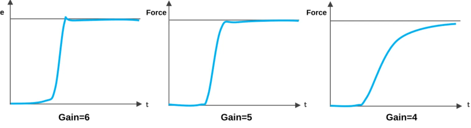
The servo press provides 11 sets of gain levels, from 0 to 10, and each level has preset P, I and D parameters that have been carefully evaluated. The press is preset with the most suitable settings for widespread use before it leaves the factory. If the desired pressing accuracy cannot be achieved after adjusting [Pressing Velocity] to a low speed, users can reduce the gain gear and change the deceleration curve to increase the pressing accuracy.
The servo press calculates the gain parameters based on the overforce and the rise time during the pressing process. When you have finished auto-gain tuning, touch [Write] to write the current gain into the recipe and touch [Gain Tuning] to disable the auto-gain tuning feature. Depending on the model, these values are set to the factory settings before leaving the factory.
This value is the speed at which the spindle returns to the origin under [Initialize] and [Manual Control]. NG Alarm If this function is enabled, an alarm will sound if the urgent result is NG. Curtain When the light curtain is enabled, an alarm is activated when the machine detects an abnormality in the light curtain signal.
Alarm Record
I/O Monitor
External Control
COMM. Setting
I/O and Communications Definitions
External Process
- External Control Initialization
- External Control Recipe Change
- External Control Reset Error
- External Control Safety Signal Interrupt
Communications Data Capture
- FTP Connection Information
- Modbus Connection Information
Alarm
Alarm Handling Method
Touched the light curtain by mistake, the spindle returns to the work origin after reset and waits for the press signal again. Release the two-handed switch, the spindle returns to the work origin after reset and waits for pressing. In the position mode, it will reach the target position according to the value from the Linear Optical Encoder which can avoid the error from the deformation due to the pressing force.
Then use the jog mode to move the spindle into the range of the optical linear encoder. Suggested to apply the default parameter at the beginning and do the fine turning according to the requirements. When the punch enters the range of the optical linear encoder, the value is displayed.
In the position mode, the servo press will reach to the target position based on the optical linear encoder. Please connect the button to the control box, refer to the installation manual, then follow the steps below to set up this mode. The two manual start buttons must be touched simultaneously to perform the pressing process.
If one of these buttons was released, the servo press will stop and return to the working origin after pressing the reset button. If the light curtain is on, the two-hand start button can be released after the pressing process begins. If MES is TRUE, the servo press will not be controlled by the completed captured signal.
MES connection delay alarm: If there is no response after 3 seconds delay, the servo press will display the message below. If they are different, the servo press will display the message and ask the user to change the recipe or cancel the process. When the product amount reaches the [Expected Amount], the corresponding message will be displayed to remind the user to perform the [Check Out] procedure.
If you select [Abandon], the servo pressure will inform the MES to clear the part number and wait for the new part number entered by the user. If the MES response does not allow to perform the pressing process, the servo press will display the message to remain the user.