DESIGN OF A SOLAR HOUSE
BY
MICHAEL ROBINSON
A THESIS
SUBMITTED TO THE FACULTY OF ALFRED UNIVERSITY
IN PARTIAL FULFILLMENT OF THE REQUIREMENTS FOR THE DEGREE OF
MASTER OF SCIENCE IN
ELECTRICAL ENGINEERING
ALFRED, NEW YORK
SEPTEMBER, 2012
Alfred University theses are copyright protected and may be used for education or personal research only.
Reproduction or distribution in any format is
prohibited without written permission from the author.
DESIGN OF A SOLAR HOUSE BY
MICHAEL ROBINSON
B.S. ALFRED UNIVERSITY (2011)
SIGNATURE OF AUTHOR
APPROVED BY
DR. XINGWU WANG, ADVISOR
DR. JIANXIN TANG, ADVISORY COMMITTEE
DR. WALLACE LEIGH, ADVISORY COMMITTEE
DR. JOE ROSICZKOWSKI, ORAL THESIS DEFENSE ACCEPTED BY
DOREEN D. EDWARDS, DEAN KAZUO INAMORI SCHOOL OF ENGINEERING
(Signature on File)
(Signature on File)
(Signature on File)
(Signature on File)
(Signature on File) (Signature on File)
iii
ACKNOWLEDGMENTS
I would like to thank Dr. Wang and my committee members for the guidance and help throughout my thesis work. I would also like to thank Joe Terranova, Avery Sandler, and Erik Wake for additional help with the thesis work. The biggest thanks goes to family and friends for their support while I was school pursuing my degree.
iv
TABLE OF CONTENTS
Page
Acknowledgments ... iii
Table of Contents ... iv
List of Tables ... vii
List of Figures ... viii
Abstract ... xii
I. INTRODUCTION ... 1
A. Solar Decathlon Energy Efficient ... 1
II. BUILDING CONSTRUCTION ... 2
A. Foundation ... 2
1. Temporary House Foundation ...2
2. House Decking...4
B. Stucture ... 5
1. 2”X4” vs. SIP Panel Construction ...5
a. 2”X4” ...5
b. SIP Construction ...6
2. Interior & Exterior ...7
a. Interior ...7
b. Exterior...8
C. House Assembly ... 8
1. Step 1 ...8
2. Step 2 ...9
3. Step 3 ... 10
4. Shipment of Components... 10
D. Wire Connection for Outlets and Switches ... 11
E. Glass Atrium ... 15
F. House Roof Design ... 17
1. Funnel Roof ... 17
2. Saw Tooth Roof ... 18
III. ELECTRICAL LOADS AND HOUSE SYSTEMS ... 19
A. Electrical ... 19
1. Electrical Outlets ... 19
v
a. Electrical Outlet Schematics ... 20
i. Bedroom Circuit ... 21
ii. Office Circuit ... 22
iii. Utility Room, Bathroom, and Hallway Outlets ... 23
iv. Living Room Outlets ... 24
v. Kitchen Outlets ... 25
b. Loads of Outlet Circuits ... 26
c. Safety Protection ... 26
2. Electrical Lighting ... 27
a. Lighting Schematic ... 28
i. Bedroom, Office & Utility Room Lights ... 29
ii. Living Room Lights ... 31
iii. Kitchen & Dining Room Lights ... 32
b. Loads of The Lighting Circuits ... 33
c. Lighting Units ... 33
i. CFL ... 33
ii. LED... 33
iii. Incandescent Light Bulbs ... 34
B. Solar Village Connections ... 37
1. Electric Connection ... 37
2. Sewer Conection ... 39
3. Water Connection ... 39
C. Hot Water System ... 40
1. Solar Preheat ... 40
2. Solar with On-Demand Heater ... 41
3. Solar Heat Only ... 41
D. Water Usage ... 44
E. Major Electical Loads ... 45
F. Mini Contests ... 49
1. Comfort Zone Contest ... 49
2. Appliance Contest ... 50
a. Refrigerator & Freezer ... 50
b. Clothes Washer ... 52
c. Clothes Dryer ... 52
d. Dishwasher ... 53
e. Hot Water ... 53
vi
G. Components For Wiring Home ... 54
H. Solar Panels and Grid Tie ... 55
1. Solar Panels ... 55
a. Additional Panels ... 58
i. Funnel Style Roof ... 58
ii. Saw Tooth Style Roof ... 62
2. Grid Tie Inverter ... 63
I. Atrium ... 65
1. Thin Film ... 65
2. Thermal Panels ... 66
J. Control Systems ... 67
IV. CONCLUSION ... 71
V. FUTURE WORK ... 72
VI. REFERENCES ... 73
vii
LIST OF TABLES
Page
Table 1: Outlet Circuit Estimation. ... 26
Table 2: Lighting Loads. ... 33
Table 3: Lumens By Different Bulbs. ... 34
Table 4: Standard Light Levels With Needed Lamps. ... 35
Table 5: Power Consumption Per Light... 35
Table 6: LED Lights Needed Per Track When running At 5W Per LED. ... 36
Table 7: Estimated Water Usage for a Family of Three ... 44
Table 8: Major Loads On House ... 45
Table 9: Wiring Components For Solar House... 54
viii
LIST OF FIGURES
Page
Figure 1: Foundation Tie-Down. ... 2
Figure 2: House Floor Joist & Foundation. ... 3
Figure 3: Foundation & Joist Right Side View. ... 3
Figure 4: Decking Formation. ... 4
Figure 5: Whole House Framing... 5
Figure 6: House Assembly Step 1. ... 9
Figure 7: House Assembly Step 2. ... 9
Figure 8: House Assembly Step 3. ... 10
Figure 9: Octagon Box With FMC Wire Connected, Junction Box. ... 11
Figure 10: Wires With Wire Nuts. ... 12
Figure 11: Electrical Outlet Screws. ... 12
Figure 12: Electrical Outlet at End of Run. ... 13
Figure 13: Electrical Outlet in Middle of Run. ... 13
Figure 14: Light Switch With Power In Light. ... 14
Figure 15: Multiple Lights on One Circuit. ... 14
Figure 16: Glass Atrium Thermal Increase. ... 15
Figure 17: Funnel Roof Design... 17
ix
Figure 18: Saw Tooth Roof Design. ... 18
Figure 19: Whole House Schematic. ... 20
Figure 20: Bedroom Outlet Circuit. ... 21
Figure 21: Office Outlet Circuit. ... 22
Figure 22: Bathroom And Hallway Outlets. ... 23
Figure 23: Living Room Outlets. ... 24
Figure 24: Kitchen and Appliance Outlets... 25
Figure 25: Electrical Lighting Schematic. ... 28
Figure 26: Bedroom, Office & Utility Room Lights. ... 29
Figure 27: Living Room Lighting. ... 31
Figure 28: Kitchen and Dining Room Lights. ... 32
Figure 29: Ecotect Daylight Analysis. ... 37
Figure 30: Electric Feed To House From Solar Village Grid. ... 38
Figure 31: Electrical Feed To Utility Room. ... 38
Figure 32: Sewer Runs. ... 39
Figure 33: Water Supply. ... 40
Figure 34: Placement of Solar Hot Water Collectors on Funnel Roof Design. ... 42
Figure 35: Solar Only Hot Water System. ... 43
Figure 36: Estimated Traditional Daily Energy Consumption. ... 47
Figure 37: Energy Use by Component Throughout Day. ... 48
x
Figure 38: Daily Energy Consumption. ... 48
Figure 39: Comfort Zone Scoring Chart. ... 49
Figure 40: Refrigerator Scoring Chart. ... 51
Figure 41: Freezer Scoring Chart. ... 51
Figure 42: Clothes Dryer Scoring Chart. ... 52
Figure 43: Hot Water Scoring Chart. ... 54
Figure 44: Solar Panel Layout for Funnel Roof Design. ... 55
Figure 45: Solar Panel Mount. ... 56
Figure 46: Solar Panel Rail Mounting Bracket. ... 57
Figure 47: Solar Panel Wiring. ... 57
Figure 48: 28 Panel Equivalent Circuit. ... 58
Figure 49: Additional Panels, West Wing Upright. ... 59
Figure 50: Additional Panel, West Wing Sideways... 60
Figure 51: Funnel Roof Additional Panel Wiring... 61
Figure 52: 32 Panel Equivalent Circuit. ... 61
Figure 53: Saw Tooth Panel Layout. ... 62
Figure 54: 41 Panel Wire Layout. ... 63
Figure 55: 41 Panel Equivalent Circuit. ... 63
Figure 56: Schneider Electric 5kW Xantrex Grid-Tie Inverter. ... 64
Figure 57: Thermal Panels. ... 66
xi
Figure 58: Energy Management Block Diagram. ... 67 Figure 59: Energy Management Flow Chart. ... 69
xii
ABSTRACT
The Solar Decathlon has been created by the U.S. Department of Energy to test the design, build, and operation of an energy efficient house. The newest addition to the international solar decathlon competition has been moved to China. The competition will take place August 2013 in Datong China. The goal of the houses being built is to create a house that is both energy-efficient and architecturally pleasing to the public.
The house will be attached to the solar decathlon’s electric grid, septic, and water systems. Since the house will be attached to the electric grid, electricity will always be available for use. However, the whole purpose is to have a net electrical use of zero. To have a net electrical use of zero, the house needs to be able to produce its own electricity through solar panels, and consume the least amount of energy through the houses appliances. During the competition week, the house will be put under mini contest that will test the functionality of the house.
Building the house will need to be designed to be structurally sound on its own foundation, so it will withhold the weight of the house and all of the housing systems within. Not only does the house need to be strong but needs to be tight, so there is no energy lose or energy gain between the outdoors and in. Getting the house to Datong China has to be ready to be built upon arrival since only a week is given to build the house on site. Therefore, the house will be partially built before shipping.
To overcome most of the major loads in the house, smart energy systems will be used from the hot water system, to the lighting of the house. A monitoring, and control system will be used to control the amount of energy being used at one time by the major electrical load appliances. Also each appliance will be the most energy efficient to help drive down the amount of energy needed for each appliance.
1
INTRODUCTION
The U.S. Department of Energy Solar Decathlon is an award-winning program that challenges collegiate teams to design, build, and operate solar-powered houses that are cost- effective, energy-efficient, and attractive. Solar Decathlon China is the most recent addition to international Solar Decathlon competition. The Solar Decathlon China will take place in Datong China August 2013. The Solar Decathlon educates students and public about the cost-saving products available by clean-energy products. The solar houses demonstrate the energy efficient construction and appliances with renewable energy systems.
A. Solar Decathlon Energy Efficient
During the Solar Decathlon competition the main goal is to be the most energy efficient, throughout the week of competition. Each house is looking to have a net energy usage of zero.
Each house is looking to be able to produce enough energy to cover the day-to-day consumption used by each individual component; therefore each individual component needs to be energy efficient to consume the least amount energy from the grid. Since AC power is available from the grid, the goal is to balance the energy produced with the energy consumed. Not only does the energy consumption matter but also the engineering and looks of the house matter. Throughout the contest week each house is tested for durability and functionality. The contest week uses the components of the house to simulate the use of the home by residents. The Decathlon combines the communication and the work between students within an individual school or across multiple disciplined schools to create one functioning home.
2
BUILDING CONSTRUCTION
A. Foundation
1. Temporary House Foundation
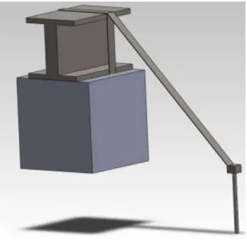
The foundation for the solar decathlon house will be similar to the foundation of a trailer home. The temporary foundation will use concrete pillars and steel I-Beams to support the load of the house during the competition. The house will use a total of three steel I-Beams. The steel I-Beams will utilize a tie-down system, used for trailer homes. The tie-down system will use metal straps that wraps around the I-Beam, and is connected to an anchor in the ground. The tie- down system keeps the I-Beam from moving side to side when building the home together on the support beams. Since the foundation is only temporary, the concrete pillars do not need to be below frost level, otherwise holes would have to be dug to get the concrete below the frost line preventing the frost from pushing the pillars up in the winter. With the temporary foundation, electrical wiring and plumbing can be run under the house and to its respected spot. With main feed to the house on the back corner of the house, the feed to the main panel would be ran under the house and up to the panel.
Figure 1: Foundation Tie-Down.
3
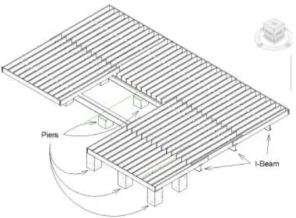
On top of the concrete pillars and steel I-Beams, the floor joist structure will be placed.
For the house flooring, we wanted to have a maximum live load of 60 lbs/ft2; so we had to look at the size of the boards we would use for the flooring. For joist spacing of 16” the maximum span could be is a little less than 14ft. With the house using a span of 14ft would work to create sections within the house. 2”X10”s will be used for both the house flooring/foundation and for the decking to give a maximum live load of 60 lbs/ft2.
Figure 2: House Floor Joist & Foundation.
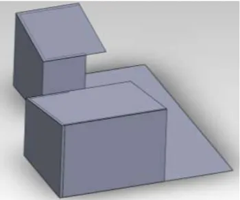
On the front right section of the house an I-Beam will not be used because there is not enough room for an entire I-Beam. Therefore, concrete pillars will span be the entire height, from the ground to the bottom of the floor joists. The concrete piers will be used to take the load of the house. The outside sill and joists will rest on these pillars.
Figure 3: Foundation & Joist Right Side View.
4 2. House Decking
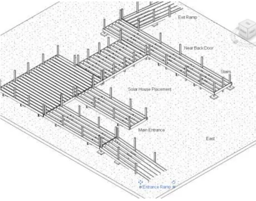
Besides having the foundation, a decking system is needed to elevate the pedestrians into the home, since the house is elevated off the ground. The decking will use 2”X10”s like the house flooring, and will be built in a similar manner. Instead of making a decking utilizing both a stair section and a ramp section, for handicap accessibility, the decking will have only two ramp sections. The ramp sections will provide easy accessibility for handicap persons and nice walkways for everyone else. Along the decking sides, there needs to be a railing system for safety. 4”X4”s will be used as up pillars, for the structure for hand rails and side rails. For the foundation of the decking, small concrete pads will be used to sit the decking joists on. The decking will also use some 4”X4” rails that go completely down to the concrete pads to give extra support where otherwise wouldn’t be. In the front of the house there could be a main entrance and in back of the house could have a main exit, both in which being a ramped section, for handicap accessibility and ease of use, therefore reducing traffic at one entrance.
Figure 4: Decking Formation.
5 B. Stucture
1. 2”X4” vs. SIP Panel Construction
There are two styles of building that can we used for the housing structure. There is the traditional building style in the United States, using 2”X4”s for wall studs and framing. Another way, and quicker construction, is using SIP panels for walls, and ceilings that are pre- manufactured.
a. 2”X4”
The structure for the solar decathlon house could be made out of 4”X4”s and 2”X4”s.
The house would be built with traditional American building techniques. The corners and connection points between the building sections will be a 4”X4” for better structure support.
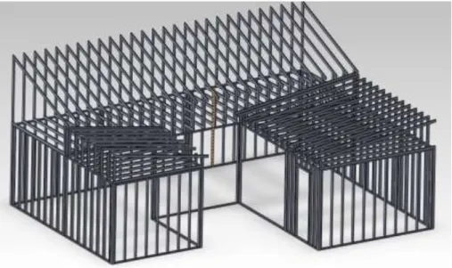
Between these points the walls will be 2”X4” stud framing. The stud framing will be 16” on center which will work with batt insulation. On top of the studs and the corner beams there will be a double header to help bring everything together structurally. On top of the header, each section of the house will have its own roof. The roof rafters will be made of 2”X10”s, which will also be spaced at 16” on center to support the weight on the roof between the solar hot water collectors and the solar panels.
Figure 5: Whole House Framing.
6
Framing around windows and doors will need to be properly fitted to support the load equally to the floor around the void made by the windows and doors, to prevent sagging. The windows would need an upper header, and a lower sill to continue framing around the windows, and to support the window. Utilizing a double stud on the sides of the windows, the support of the wall is not placed on the window itself. The double stud has a stud that is continuous beside the window from floor to top header. While a secondary stud goes from the floor up to the header above window, to support the header and the forces pushed onto it. A standard double hung window size for the installation would be around 36” by 5.5’ but can be a wide range of sizes. The doors would have a similar build structure as the windows but would not have support under it like the windows, since the door would be a wide open void in a wall. Door sizes however, would need to a minimum of 30” wide unless it is handicap accessible, which in that case would need to be 36” to allow wheelchairs through. A door height would be best between 7’
and 8’.
The back section roof facing south will have a pitch around 30⁰ to match the angle of the sun during the competition. additional framing will be placed in the center of the house to reduce the load on a particular spot to a more uniform load across the entire floor area. The load will need to be spread out because in that area a large window atrium could be used, to help heat the house using the sun.
Using wood stud framing and batt insulation the insulation value of the house would be between an R-12 and R-16. Using fiberglass batts the R value would be between R-3 and R-4.3 per inch thick. Cotton batts, which are recycled from blue jeans, would have an R value around R-3.7 per inch thick. Cotton batts are also more fire resistant than fiberglass insulation. Blown in cellulose insulation’s R value would range between R-3 and R-3.8 per inch thick. Cellulose insulation is messy and harder to control for a simple house construction like this.
b. SIP Construction
Structural Insulated Panels, SIPs, are easier and allow for quicker building of a home.
Within the panels, all electrical boxes are pre-connected with flexible metal conduit. The wiring is routed according to wiring diagrams. Even with everything pre-assembled, modifications are able to be done onsite while building. Windows and air conditioning / heating units are precut by machine, when made in the factory. Plumbing within the SIPs is possible, however with the
7
house design, the water and sewer runs can be run from under the home, to prevent the mixture of electric with water. When constructing the home, before shipping to Datong, the wall panels would be best connected using screws. However, once the house is shipped and is in Datong for final construction, the corners and connection points between the individual SIPs will need to be glued and screwed together. Gluing the panels together allows the house to have a sealed building envelope, preventing heat loss or gain of the house.
Once the walls are up, finishing the walls is simple and easy. On the inside, sheetrock/gypsum board, or any other interior finish can be applied for a smooth and pleasant looking wall. On the outside, OSB board or plywood can be used to tie everything together for more structure and allow for the finishing of the outside with either a board siding, the hardie plank or another style of siding.
The insulation factor of the SIPs is a little better than the traditional building with batt insulation. The panel has an R value of R-18 for a 4.5 inch thick panel. Between the two styles, both are relatively similar by thickness. However, using SIPs is quicker and easier.
The SIPs are connected with a 2x stud every 4ft, to join panel to panel. The panels come with finished sides of plywood to fasten sheetrock and other materials to it. Having the plywood sides makes hanging large heavy components up on the walls easy and no need for additional support.
2. Interior & Exterior
The interior and exterior of the house will be covered in fire resistant material to increase the house’s fire protection. The interior and exterior materials will also help tie everything together making an even stronger house.
a. Interior
On the interior of the house 5/8” sheetrock could be used. The sheetrock will be a good finish to hide and cover up any necessary spots and give a better finished look to the house. The sheetrock would also be fire resistant, creating a better fire resistant house. The walls would be able to be painted and made more homely. With a sheetrock finish, mudding and taping needs to take place. However, with mudding the drying time is directly related to the temperature and humidity in Datong. The longer the mud takes to dry the more time it takes to complete the house, however with having a set amount of time to build the house, the delay will need to be
8
avoided. A wood interior could be used to avoid time delays, because the wood finish could be nailed to the wall and have no drying or finishing time to it.
b. Exterior
The exterior of the home could be pre-covered in an OSB, plywood material and then followed with a finishing material. Using OSB or plywood would allow for the structure to become sturdier and all tied back together. The OSB or plywood would give the outside walls a sturdy and smooth surface to mount any kind of siding to. Hardie Plank could be used to cover the walls. The hardie plank is a fire retardant material to increase the fire protection that much more. Over the OSB, plywood, any kind of siding can be used, either a wood siding, bamboo siding, or anything that will look nice and presentable.
C. House Assembly
Putting the house together there are two ways in which the house can be put together on site at the solar decathlon in Datong. One method is to assemble the house in a modular way. The modular assembly can be used if the solar house is built by Guilin University of Technology in China, GUT. The second method is to ship wall sections to Datong China, if Alfred State College is to build the solar home.
1. Step 1
The first step would be to take the front left modular section, if built by GUT, or the left sections of panels, if built by Alfred State. The front left section is the smallest section of the house and a good starting point to build from. This section has three sides to line up and will help square up the house. This section will be assembled onto the flooring, and the section will consist of the outside walls, with the structure support. The roof then can be added to the wall sections if the house is built in wall sections. Within the section the electrical components will already be wired and ready to be hooked up to the rest of the house.
9
Figure 6: House Assembly Step 1.
2. Step 2
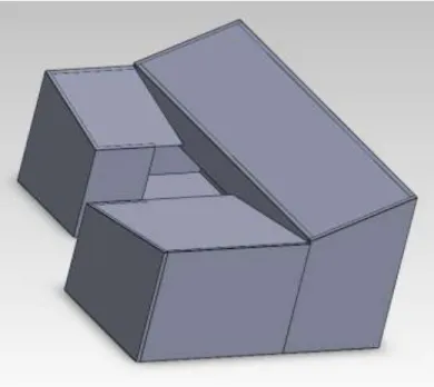
Step two will be similar to step one. The second step will take the front right section of the house and have it placed on the flooring. The whole modular section would be placed into place. With a sectional assembly the roof and wall stud structure will be assembled and placed onto the house foundation. This section will be able to be lined up with the first section to assure they are plumb and square with each other, ensuring a correct fit with the last section.
Figure 7: House Assembly Step 2.
10 3. Step 3
The last step to assembling the house would be to bring in the third and last portion of the house. The third portion is the heaviest of all the sections because this section has the largest roof area of all the modular sections, and has the most square footage of the home. With the other two sections already in place, the last section has multiple points to matchup to.
Figure 8: House Assembly Step 3.
4. Shipment of Components
If the solar house is built by Alfred State, in order to get the solar home from the United States to Datong China, the house would need to be shipped on a container ship. There are two standard container sizes, a 20 and 40 foot long container. The openings and cross-sectional areas are the same between the two, the length however between the two are different. The inside width is 7.71 feet and an inside height of 7.8 feet. Due to the size of the house sections, the house will not be able to be placed in the container in section of pre-assembled modular walls.
Therefore, each individual wall section would be placed into the container not attached to its matting wall or walls. With the wall height of the main floor of two meters tall, the walls will be able stand upright with room to spare. The house walls and roof rafters should be able to be
11
packed into one 40 foot container. However, the remaining floor, floor joists, and decking would not be able to be packed into that same container. Therefore, an additional container would be needed. The flooring joists are so big that the floor would not be able to be taken pre-assembled.
The same goes for the decking around the house. Therefore, these parts for these two components can be put into the same container together.
D. Wire Connection for Outlets and Switches
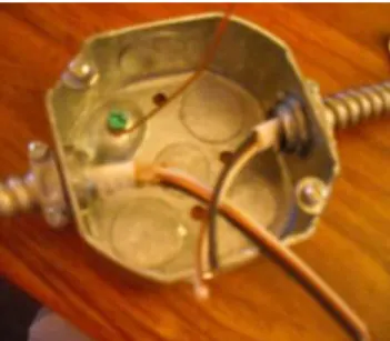
Using FMC, flexible metal conduit, wire inside of the flexible metal conduit cover contains the necessary wire for wire the home; therefore once the FMC wire is run, no additional wires would need to be run. Using an octagon metal box, as a junction box to connect between modular sections of the home so the house can be wired prior to shipping the house over to China.
Figure 9: Octagon Box With FMC Wire Connected, Junction Box.
When feeding the FMC into the box, roughly about 6 inches of wire is left, and the outer cover is stripped revealing only the neutral (white), hot (black) and ground (bare) wire are left.
Within the box a ground wire is attached to the box using a ground screw. For the junction box, the two hot wires are stripped around 5/8” to expose the bare wire and using a wire nut to
12
connect the wires. The neutral wires are done the same. The ground wires from both the cables and the ground wire in box are all twisted together tight. Therefore when everything is connected the circuit is completed. When the FMC wire is connected to a junction box or outlet box, the FMC needs to have a staple or mount holding the FMC from being able to move and come loose.
Figure 10: Wires With Wire Nuts.
Wiring outlets is done in a similar manner as the junction box. Electrical wires are brought to the electrical box with the FMC wire and connected to the outlet. For connecting the outlet to the supply the neutral wire is connected to the same side as the ground screw. Like in the junction box, a ground screw is used with a ground pigtail connecting the ground wire of both wires, the ground screw on the outlet and the ground screw connected to the box all together.
Figure 11: Electrical Outlet Screws.
13
Connecting the wires to the screws on the outlet is done by using a pair of needle nose pliers to round the end of the wire to wrap around the screw. Once the wire is around the screw, the needle nose pliers are used to squeeze the wire tight around the screw. Doing this makes the wire tight enough that even if the screw comes loose the wire will not come off. Since the outlet has four screws, this allows for the outlet to be used in the middle of a run and at the end.
Figure 12: Electrical Outlet at End of Run.
Figure 13: Electrical Outlet in Middle of Run.
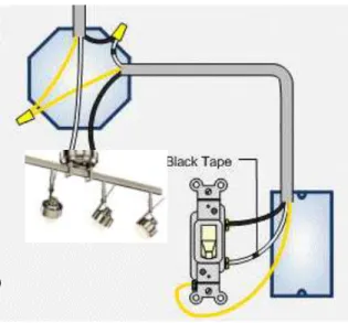
Wiring for the lighting in the solar house will be wired similar to the junction box. The power feed will be fed into the box through the FMC cable from the electrical panel. In a similar way the junction box was wired the lighting box will be wired. The power for the lights will be in the ceiling “Power in the light,” and then using a 2 wire, the neutral wire will be connected to the hot wire in the box and fed down to the lighting switch. From the lighting switch the hot wire will be fed back up to the light to complete the circuit to the light.
14
Figure 14: Light Switch With Power In Light.
When multiple lights are connected together, the lights are connected the same way the outlets are. The lights are connected together keeping all the neutral wires and all the hot wires connected together, and using pigtails connecting the wires to the lights.
Figure 15: Multiple Lights on One Circuit.
15 E. Glass Atrium
In the very center of the house, a glass atrium is being placed. The glass atrium will be used as a heat source throughout the day. However, initial calculations have been done on the glass atrium, and the atrium will draw in too much heat, and make the cooling system run more than it is desired, using more electricity than planned. To overcome this issue, several options need to be looked at to reduce the amount of energy brought into the house.
Figure 16: Glass Atrium Thermal Increase.
16
Using Ecotect from autodesk a simulation of the fully enclosed glass atrium in the middle of the house can be viewed according to weather data for Datong China in August. The simulation shows the increase in temperature at noon on the 7th of August. In the atrium the temperature within reaches an increase of almost 30℃, and an increase in the house around 21℃.
One option to decrease the amount of sunlight the glass atrium would capture is to use three sides of the atrium, on the bedroom, hallway, and living room walls, as a large window.
Using the large windows would still allow natural light and warmth into the house on the three portions of the house. By removing the other sides of the atrium, the interior is not continuously increasing in temperature; the interior of the house is being warmed just when the sunlight is coming directly through the windows. Inside of the new void a little pond for looks could be placed, and utilize the roofs to funnel the rain water into the pond area.
Another option that would help the most would be to use thin film solar panels between two panes of glass of the atrium. With the double layer of glass and the thin film between the panes, not all the light will be passed through to atrium. And the thin film panels will create a voltage and current depending on the amount of sunlight on the atrium. Using the thin film, the film would act like a set of blinds behind the glass. The thin film would help control the amount of light allowed through into the atrium. Therefore, allowing for not too much heat to be produced and allowed into the house.
The option that would help the best is to remove most of the atrium. Placing large windows on the interior sides of the house where the atrium normally would have been in contact with the interior of the house would reduce the heat gain. Keeping these windows here would still allow for sunlight to be allowed into the house throughout the day. The windows then could still have thin film solar panels and/or blinds to control some of the sunlight. The windows would allow for some warmth to enter the house, however the amount of heat would not be anywhere’s close to the amount of heat the atrium would produce. Since the atrium would be continuously warming up throughout the day, the heat would expand into the house, but with the only the windows only direct sunlight would be allowed to pass through.
17 F. House Roof Design
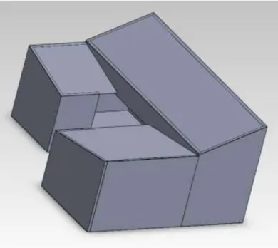
The roof design of the solar house has had a few design suggestions. Whether the roof top is a funnel type roof suggested by Guilin, the roof funnels everything to the middle from the back and the sides, or suggested by Alfred State a saw tooth style of roof.
1. Funnel Roof
With a funnel style roof, designed by Guilin, the roof top has some advantage and some disadvantages. The large back section of the roof is a good use for solar panels to collect sunlight to create electricity to overcome the energy consumption of the house throughout the testing week of the house, through the mini contests. Also with the funneling, water from when it does rain can be collected in one centralized location. The funnel style roof design would allow for 28 solar panels to be placed on the large back section of the house. An additional set of four panels then could be added with the 28 panels to make 32 panels in total that could be used. When attaching components to the roof, most components need to be facing South. Due to the West side slanted down towards the middle, additional panels would cast shadows on the panels behind if spaced too close together due to having to put the panels at an angle to face the sun.
Figure 17: Funnel Roof Design.
18 2. Saw Tooth Roof
A saw tooth design also has its own advantages and disadvantages. With a saw tooth style roof not only will the large back section be facing the South, at the correct angle, but also the two side sections. With having the West wing set at the correct angle to the sun, the issue with casting a shadow is avoided since the panels will be flat on the roof. With the saw tooth design, when it rains the water would travel down both the East and West sides, and be collected in two separate locations. With the availability to add even more panels to the roof, with the saw tooth design, 41 panels could be placed on the roof top.
Figure 18: Saw Tooth Roof Design.
19
ELECTRICAL LOADS AND HOUSE SYSTEMS
For the solar decathlon house, the house is going to be viewed in China and connected the Chinese AC grid. The Chinese grid is 220V and 50 Hz compared to the standard 120V 60 Hz in the United States. For wiring the electric in the solar home all wiring would be done in FMC wire. FMC is flexible metal conduit. FMC is a raceway of circular cross section made of helically wound, formed, interlocked metal strips. With the FMC wire there should not be more than four quarter bends (totaling 360 degrees) in one run. Using FMC cable with metal octagon boxes and metal outlet boxes the two should work nicely together with connectors. The electrical loads will be drawing electricity from the grid to power the components within the house.
Whereas some of the systems will help maintain functionality of the house and limit the loads in which the house sees. The electrical schematics where drawn using a version of SmartDraw software.
A. Electrical
1. Electrical Outlets
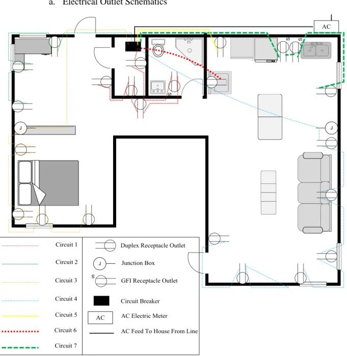
For electrical outlets the spacing between outlets cannot exceed 6ft (1.82m). Each wall has to have an outlet; a wall is defined as a wall over 2ft (.6m) in length. Also the wall must be a fixed wall, so the back side of a lower cabinet in a kitchen would be classified as a wall.
Standard gauge wire used for outlets is 12 AWG 2-wire with a 20 Amp breaker. Wiring within the house will be run throughout the walls and ceiling throughout the house. Using the FMC wire the wire has no problem going through the wall’s interior material. Some electrical outlets need to be a GFI outlet. A GFI outlet is a Ground Fault Interrupt outlet. A GFI is used when an outlet is within 3ft (.91m) from the edge of a water source. Each breaker for each outlet circuit will be a GFCI breaker, Ground Fault Circuit Interrupt. The GFCI will keep the circuits from shorting out shocking people. Duplex receptacle outlets will be used for all receptacles except for GFI outlets.
The duplex receptacle is an outlet with a two sets of outlets, seen in figure 11.
20 a. Electrical Outlet Schematics
Buy SmartDraw !- purchased copies print this document without a watermark .
Visit www.smartdraw.com or call 1-800-768-3729.
Figure 19: Whole House Schematic.
Throughout the solar home, there are multiple outlet circuits. Each outlet circuit is broken up by rooms and applince due to the fact that some circuits draw more current than others. Like in normal houses, rooms and floors are broken down into their own circuit, however due to the fact that the solar house will be reassembled using house modulars, thre is the need for additional circuits.
21 i. Bedroom Circuit
Figure 20: Bedroom Outlet Circuit.
For the bedroom circuit, a feed line comes from the electrical junction box and running the FMC wire through the wall and through the rafters in the ceiling of the office. After running
22
from the breaker through the office towards the bedroom, the FMC will connect to a junction box. The junction box will be on the office side of the junction between the house sections.
Therefore, when the house is connected back together, the junction box will connect to the FMC in the bedroom. From the junction box, the wire will run within the walls of the bedroom. The outlets should not be off the floor more than 20in (.5m). Since the outlets need to be spaced no more than 6ft in distance between each other, there will be two outlets on each side of the bed and two more outlets on the South facing wall of the bedroom.
ii. Office Circuit
Figure 21: Office Outlet Circuit.
23
The office outlet circuit will start from the utility room circuit breaker panel and go through the back wall of the house, up and over the back door frame and then back down the wall to the first outlet. From the first outlet the FMC will continue through the wall and around the corner to the other two outlets.
iii. Utility Room, Bathroom, and Hallway Outlets
Figure 22: Bathroom And Hallway Outlets.
Since the hallway the wall area is longer than 6ft in length, an outlet is needed to meet code. Along with the hallway, inside the utility room, and the bathroom will need outlets. Inside the bathroom a, GFI, ground fault interrupt, outlet will be used to since it is within 3ft of the sink. A GFI outlet will prevent short circuiting and the risk of electric shock. The outlet feed will begin in the utility room and go to the bathroom outlet and run back along the hallway and around the corner.
24 iv. Living Room Outlets
Figure 23: Living Room Outlets.
The outlets for the living room will be in the similar way like the bedroom. Since the living room will be its own modular section when the house is assembled, the feed for the outlets will be run to junction box close to the junction between the two sections of the house. From the
25
junction the FMC line will then run down the wall to the first outlet on the run. Feeding the power will be fed from the first outlet to the next five outlets through the wall. When the power gets to the last outlet, the feed will have to run up and over the front door framing and then back down to the last outlet.
v. Kitchen Outlets
Figure 24: Kitchen and Appliance Outlets.
The kitchen has the most amount circuits of the whole house. Within the kitchen there are a total of three individual circuits. There is an outlet circuit for running outlets above the countertop. Two of these outlets will be a GFI. These outlets need to be a GFI outlet to meet code, since the outlets will be within 3ft of water. On the same outlet run as the GFI outlets will be an additional outlet on the right side of the kitchen. Another circuit within the kitchen is the Refrigerator and Microwave circuit. The third circuit in the kitchen is for the washer dryer unit.
The washer and dryer circuit will be run with an 8 AWG gauge wire with a 35 Amp breaker in the circuit breaker panel. The circuit needs an 8 gauge wire because of the high current of the dryer.
26 b. Loads of Outlet Circuits Table 1: Outlet Circuit Estimation.
Outlet Loads
Circuit Size of breaker
(Amp) Volts Number of Outlets
Estimated Current per Outlet (Amp)
Estimated Load per Outlet (W)
Total Load of Circuit (W)
Bedroom 20 220 4 1 220 880
Office 20 220 3 1 220 660
Utility
Rm./Bath 20 220 5 1 220 1100
Living Rm. 20 220 6 1 220 1320
Kitchen 20 220 3 1 220 660
Washer &
Dryer 35 220 1 22 4700 4700
Fridge &
Microwave 20 220 1 7 1600 1600
Total 10920
When estimating the loads on the electrical outlets each outlet that does not have a dedicated load on it, the estimated amperage for each of these outlets is 1 Amp. The actual amount of current being pulled from the outlet would be less than the estimated one amp. If the estimation is larger than the single unit would be seeing, the load for the circuit would be overestimated. Therefore, if something was plugged into each electrical outlet and all circuits were being used at the same time the estimated total load on the electrical system would be 10kW. However, during the solar decathlon competition, every outlet should not be in use at the same time. But, the outlets are needed to pass electrical codes.
c. Safety Protection
Just like in every home, safety factors are considered and implemented. For the solar home multiple safety factors will be looked at. First, electrical circuits utilize a safety factor, typically 1.25. The safety factor can give you an idea of what the maximum current one would want to put onto a circuit, to give room for overdrawing on the circuit. For a 20 Amp breaker utilizing the safety factor of 1.25 the maximum current the circuit should be designed for is 16 Amps. This is found by taking the breaker nominal value and dividing it by the safety factor. The
27
same would be done for the other circuits within the house. In the outlet circuits each circuit would have 20 Amp breaker, therefore the maximum current that would be wanted to run on that circuit is 16 Amps. Knowing that 16 Amps can be ran on one circuit and an estimated 1 Amp draw per outlet, determines there could be a total of 16 outlets on the one circuit. However, due to code, there cannot be 16 outlets on one circuit. Therefore, each circuit was designed to meet both code for electrical outlets and to be under the maximum current the circuit should handle.
Making sure the size of the breaker is large enough while being able to have the enough outlets that still meet the code requirements.
Ground fault protection will be utilized throughout the house as well. For all the outlet circuits back at the breaker panel, each breaker will be a GFCI, ground fault circuit interrupt.
This will ensure that every electrical outlet circuit will be protected for short circuiting and electrical shocking of pedestrians while in the home. The GFCI is a breaker that when it detects short circuiting, the breaker will “trip” and cut power to all the electrical outlets on that circuit.
The breaker will also work like a typical circuit breaker. A circuit breaker “trips” when the current in the circuit is over the nominal value of the breaker. The breaker trips preventing damage to the circuit and electrical components within the house. In the kitchen the electrical outlets, within 3ft of the sink, will be GFI, ground fault interrupt, outlets. The GFI outlets acts the same as the GFCI breaker, in that when there is a detection of a short the outlet itself will trip and will need to be reset. Using both a GFCI breaker on all electrical outlet circuits and GFI outlets in the kitchen provides both double security of electrical shorting and shocking within the house, protecting both pedestrians and electrical components within the house. The GFCI breakers will be a Square D breaker available from Schneider Electric.
2. Electrical Lighting
For the lights the standard gauge wire used for outlets is 14 AWG 2-wire with a 15 Amp breaker. Wiring within the house will be run throughout the ceiling of the house. The lights for the house will all be high efficiency lights to keep energy consumption down. For some rooms more than one circuit will be needed. The lighting switch for each light will be a proximity sensor switch. So when the room is not in use for a set amount of time, the lights will turn off saving a little power at a time. However, once someone enters the room the lights will turn back on again. The proximity sensor switch is a manual-on and auto-off switch, made by Square D,
28
which is part of Schneider Electric. The switch will have a time out of up to 30 minutes and will be able to be turned on and off manually when the day starts and when the day ends.
a. Lighting Schematic
Buy SmartDraw !- purchased copies print this document without a watermark .
Visit www.smartdraw.com or call 1-800-768-3729.
Figure 25: Electrical Lighting Schematic.
The lighting circuits for the house are broken up into six different circuits. The bedroom and living room both are their own circuit, mainly because due to the modular assembly, the
29
circuit as to be disconnected and then reconnected once reassembled in China. With the multiple circuits the control of the wiring for the lights can be managed much easier.
i. Bedroom, Office & Utility Room Lights
Figure 26: Bedroom, Office & Utility Room Lights.
30
For the bedroom lights the feed for the lights will be brought through the ceiling to a junction box between the main section and the bedroom sections of the house. From the junction box the power will be fed to the light and then down to the switch. With this setup the power will be in the light, and only one wire will be needed to run a connection down to the switch. With the power in the light, the neutral wire being fed to the switch will be connected to the hot wire in the light, the neutral wire acting as a hot wire will be connected to the switch and the hot wire from the switch will then supply power to the light. The hot wire from the switch and the neutral wire from the feed line will be connected together to complete the circuit. The switch will be on the corner of the bedroom on the support beam by the glass enclosure.
The office lights will be similar to the bedroom lights. The power will be fed to one light then the power fed to the switch for the office via the neutral wire. The hot wire will return to the light hot. From there, using a pig tail, to feed the first light and continuing the feed to the next light. On the office side of the hallway, there is another light on the same circuit. This light is there for when traveling from the bedroom to the kitchen at night, the light in the hallway will give some light on the other end of the hallway to find the next light switch. In the utility closet, a light is needed for work while in the room therefore a light switch will be located on the outside of the room next to the door for easy access.
31 ii. Living Room Lights
Figure 27: Living Room Lighting.
The living room lights will be similar to the Bedroom lights, in the way the power will be in the lights and the use of a junction box will be used to feed power to the lights. A Switch by
32
the front door will control both lights in the living room, much like the office lighting did. A light by the front door will give enough light to see when entering into the house. While the light in the middle of the room will give off light while sitting in the living room.
iii. Kitchen & Dining Room Lights
Figure 28: Kitchen and Dining Room Lights.
For the kitchen lights, the lighting will be split into two sections. One set of lighting will be by the sink, counter and refrigerator and the other over the dining room table. The set of lights by the kitchen counter will be on its own switch and the light over the dining room table its own.
Having the two different sets will allow for using the lights while eating and then have that set off while cooking and preparing food. Doing so will reduce the amount of power used by the house when there is no need for the lights.
33 b. Loads of The Lighting Circuits Table 2: Lighting Loads.
Light Loads
Circuit Size of Breaker (Amp)
Number of Lights
Estimated load per light (W)
Total load of circuit (W)
Bedroom 15 1 50 50
Office 15 1 50 50
Utility Rm./Bath 15 2 50 100
Living Rm. 15 2 50 100
Kitchen 15 4 50 200
Total 500
The lights used in the solar decathlon house will be high efficiency lights, utilizing light emitting diodes, LEDs. Using LEDs will give off enough lumens while consuming a low amount Watts. If every light was to on and left on all at the same time the total load on the house would be around 100 Watts.
c. Lighting Units
Lighting for the solar decathlon house will be needed for during the day and night to meet the necessary standard lighting lux of a room. Light bulbs for the house can range from compact fluorescent lights, CFL’s, Incandescent light bulbs and LEDs. Each room of a house has its own standard light level needed to perform standard tasks.
i. CFL
The compact fluorescent light, CFL, is more energy efficient and longer lasting replacement for incandescent lamps. A CFL that is a replacement for an incandescent lamp that has a built in ballast that can last 60,000 hours. CFLs compared to incandescent lamps use 20- 30% of the energy.
ii. LED
Light emitting diodes, LEDs, use the least amount of energy of all the lighting lamps.
High power LEDs produce light while consuming very little energy, while lasting up to 60,000 hours. Newer high power LEDs produce up to 100 lumens/Watt, therefore using much less power per lumen compared to incandescent lamps.
34 iii. Incandescent Light Bulbs
Incandescent lamps are the oldest form of lighting technology. These lamps are also the least efficacious and have the shortest life span. Incandescent lamps have a tungsten filament, which current is passed through, making the filament hot and glow. Over time the filament evaporates and breaks. Incandescent light bulbs produce enormous amounts of heat from the burning of the filament.
Lights have a measured amount of lumens produced depending on the size of the light bulb. The higher the wattage of light bulb the higher the average lumens produced, and the more energy consumption of the light bulb. CFLs and Incandescent light bulbs both produce the same amount lumens for the same rated wattage, however the amount of watts actually used in a CFL is much less. One Lux is equivalent to one lumen/m2.
Table 3: Lumens By Different Bulbs.
Light Bulb Size Lumens Produced
60 W 800
CREE XP-E LED @ 5W 500
CFL 12W 500
Depending on the standard amount of lux needed for each room, and the area of the room the number of lumens needed is found. Using the total number of lumens needed, the number of lights for each room is found.
35
Table 4: Standard Light Levels With Needed Lamps.
Standard
Lux
Area (m^2)
Lumens Recommended
For Room
Number of Lights Needed Incandescent
60 W LED CFL
Bedroom 200 10 2000 3 4 4
Office 500 11 5500 7 11 11
Hallway 100 4 400 1 1 1
Bathroom 850 4.5 3825 5 8 8
Kitchen 850 10 8500 11 17 17
Dining Room 450 5 2250 3 5 5
Living Room 200 13 2600 4 6 6
Totals 34 52 52
The total number of lights needed to illuminate the house for each style of light ranges due to the lumens produced by the light. For incandescent light bulbs 34 light bulbs would be needed which is much less than the other two light form, but uses ten times the power. LEDs and CFLs both would need 52 light bulbs but the LEDs would consume a third of the power the CFLs would consume.
Table 5: Power Consumption Per Light.
Power
Rating (W)
Number Bulbs
Total Power Consumption (W)
Incandescent 60 34 2040
LED 5 52 260
CFL 12 52 624
The LED lighting for solar decathlon house will be a new and different style of lighting.
Normal lighting that uses LEDs are replacement bulbs that use a standard light socket connection, or are a pot light that is wired in and has a built in AC-DC converter. However, for the solar decathlon house, the use of CREE’s XP-E LEDs a new lighting element can be produced. With the LEDs an 80° diffusion lens will be used to distribute the light evenly down onto the floor. A fan like aluminum heat sink would be used to help dissipate the excessive heat from the lamp.
36
The light intensity produced from each LED lamp is roughly 100 lumens per Watt.
Connecting five to 10 of these lamps together will give enough lumens recommended for each room; therefore these lamps set to one Watt would be able to dissipate 500 to a 1,000 lumens. If the lights are set to run at 5W per LED, the lamps could dissipate 2,500 to 5,000 lumens per light fixture. Since the LEDs run off DC, and the house will be running AC, the AC must be converted to DC. Using a bridge rectifier the AC is brought to a positive ripple. The addition of a capacitor then smooth’s out the ripple to a more continuous DC voltage.
Table 6: LED Lights Needed Per Track When running At 5W Per LED.
LEDs
Needed
Number Of Lights Per Track
Number Of Tracks
Bedroom 4 5 1
Office 11 6 2
Hallway 1 1 1
Bathroom 8 10 1
Kitchen 17 10 2
Dining Room 5 5 1
Living Room 6 5 2
With the LED lighting, a track lighting system could be used to connect between five to 10 LEDs. With the track lighting either the lights could be hung downwards from the track, or the lights could be manipulated to shine in the necessary directions needed to cover the entire room.
37
Figure 29: Ecotect Daylight Analysis.
Ecotect analysis shows the bathroom and utility room receiving around 3,600 lux while the highest point can reach up to 5,600 lux, which are by the outside windows on the perimeter of the house.
B. Solar Village Connections
All utilities that will be provided to the solar house will have their own connections to the solar village. The utilities provided by the solar village are the electric, sewer, and water supply.
The connections of these amenities will be connected either behind the house or under the house.
Only water, electric, and sewer connections will be provided, other amenities desired for the competition must be pre-arranged.
1. Electric Connection
The electric connection between the solar house and the solar village grid could be placed in the back of the house. The electric meter could be outside the house to free up space within the utility room of all components, and makes the connection easier. From the electric meter,
38
underground conduit will be run under the house and up through the interior wall, between the bathroom and utility room. Feeding the conduit under the house prevents the possibility of damage to the wire due to traffic of viewers.
Figure 30: Electric Feed To House From Solar Village Grid.
The electrical feed from the solar village grid could also be fed underground, in a similar way like before when the meter was outside, and then run up into the house into the utility room to where the two way net meter would be located. However with running the electrical feed under the house both options would have to keep the main water supply a minimum 30 inches away from each other.
Figure 31: Electrical Feed To Utility Room.
39 2. Sewer Conection
Sewer connections from the solar house will all come together at one location, and leave the house. From all of the corresponding sewer starts, the plumbing will be ran down under the house within the spacing between the ground and the floor joists. All plumbing will have to have a pitch to it. With a pitch to the piping, the sewer runoff will be allowed to flow. If the piping was to have no pitch or too little of a pitch, sewer can become blocked or partially filled. All plumbing has to have the same pitch all going towards the main drain. Once reaching the main drain out the sewer will leave the house through underground plumbing. For the plumbing to function properly, all plumbing runs need to have their own ventilation. Ventilation is needed for the sewer to flow through the plumbing, otherwise the plumbing would work like a vacuum and no flow would be possible.
Figure 32: Sewer Runs.
3. Water Connection
Water supply to the house will also be supplied underground, to prevent damage from pedestrians. The water supply will then be connected to the house’s supply line under the house.
From the connection under the house, cold water supply then would be ran to the hot water heater, the sinks in the bathroom and kitchen, and to the bathroom toilet and shower. From the hot water tank, the hot water runs will then supply hot water to the same locations of the cold water.
40
Figure 33: Water Supply.
C. Hot Water System
There are a few ways to heat water for the solar decathlon, by either using a solar pre heat system, solar with an on demand heater or only solar collectors. Each has its own advantages and disadvantages. With a hot water system, 1 BTU raises 1 pound of water 1℉. 1 gallon of water is 8.345 pounds, therefore 83.5 BTUs will raise 10 gallons of water one degrees F. To have enough water for mini contests and for the random water draws, up to three draws back to back, therefore an 80 gallon tank should be used. With the use of solar for hot water, either an active or passive solar system could be used. A passive system uses no additional energy to move the water throughout the system, while am active system uses a pump to circulate the water.
1. Solar Preheat
Using a solar preheating system the water would be warmed using the solar collectors, and then a traditional electric hot water heater would be used to get the water up to the desired water temperature. Therefore, with an 80 gallon tank and 40 gallons are heated to half of the desired temperature the heating element would need to heat the remaining 40 gallons. With an 80 gallon tank, the heating element(s) within the tank have an average power consumption of 5kW.
41
Therefore, if the tank takes an hour to raise the remaining water to the desired temperature there would be an additional 5kW of energy consumed by the house. The water tank in the house would both have to hold the water at its set point and not lose the water temperature over time, while also creating more of an energy draw on the house that is not expected.
2. Solar with On-Demand Heater
With a solar heat system with an on demand heater the solar collectors can heat the water and hold the water in a hot water tank to keep the water from losing its temperature. Then once hot water is needed the water runs through the on demand heater to increase the water temperature to or above the desire point. On demand systems are good because they can raise the water temperature 40℉ while still keeping a good flow rate of water. To get the necessary water out during the water draws the water has to have at least 4 gallon/minute flow rate. With a flow rate of 4 gallons a minute, the normal increase in water temperature is 60℉. However, with the on demand system the power consumption of the heater is around 30kW, much more than what a normal electric hot water heater would use. But the on demand system would be on for less time than the hot water tank would be on for.
3. Solar Heat Only
The hot water system is important system for the solar house. It’s important because within the solar house competition, there is a hot water mini challenge. Having the competition, means there is a minimum standard in which is needed to be reached. Using a traditional electric hot water tank to heat the water takes a lot of energy however, since the main goal of the competition is to consume the least amount of energy, a traditional electrical tank would use way too much electricity. Therefore, a solar hot water heater system from Apricus would be better suited for the task. Using two 30, or more, evacuated tube systems to heat water in the hot water tank, would ensure the water reaches the necessary temperature. The evacuated tube systems would attach to the roof of the front section of the house, on the East side next to each other.
Apricus system could be used because, for other solar decathlon houses in previous decathlons their systems have been used to meet the demands of the competition.
42
Figure 34: Placement of Solar Hot Water Collectors on Funnel Roof Design.
The hot water tank system takes the cold water into the house and feeds it through the hot water tank and through the solar collectors. Using a controller unit the water from within the tank can be circulated through both collectors and back into the holding tank to heat the water within.
The controller will continue to circulate the water throughout to turn the tank temperature up to its desired temperature. Once hot water is wanted within the house, the water from the tank will then go out the hot out point to the rest of the house.
43
Figure 35: Solar Only Hot Water System.
According to the manufacture, the output of a 30 evacuated tube collector is 3412 BTU/hour. With the output of one collector, and a 40 gallon tank the water will increase 10.2℉
per hour. With an eight hour day, the water temperature would increase 81.77℉. Therefore, if the cold water into the house is around 40℉, in the eight hours, the water would increase in temperature to 121℉. If two collectors are used, the water temperature would increase 20.4℉ per hour making the water in the tank, after eight hours, reach 203℉. With a single solar collector, and an 80 gallon tank, the water would increase 5.1℉ per hour. Therefore, over eight hours the