O F
SHALLOW ARCHES WITH ELASTIC END RESTRAINTS
T h e s i s by T e r r y Joseph Delph
In P a r t i a l Fulfillment of the Requirements F o r the Degreeof
Aeronautical Engineer
California Institute of Technology Pasadena, California
1949
i i
ACKNOWLEDGMENT
The a u t h o r w i s h e s to e x p r e s s h i s a p p r e c i a t i o n to Dr.
C. D. Babcock, J r , f o r h i s valuable guidance a n d a d v i c e during t h e c o u r s e of t h i s work. Thanks a r e a l s o due to Dr. M. C. Cheung, and to M r . C l a r e n c e Hemphill of t h e E l e c t r o n i c s L a b o r a t o r y , f o r t h e i r patient help. M i s s Helen B u r r u s and M r s . Betty Wood w e r e r e s p o n s i - b l e f o r the typing and t h e f i g u r e s r e s p e c t i v e l y , a n d t h e i r a s s i s t a n c e i s
gratefully recognized.
T h i s study w a s supported b y t h e A i r F o r c e Office of Scientific R e s e a r c h , Office of A e r o s p a c e R e s e a r c h , United S t a t e s A i r F o r c e under Grant N u m b e r AFOSR 68
-
1424.ABSTRACT
A t h e o r e t i c a l and experimental study of the buckling under impulsive load of a n a r c h with rotational end r e s t r a i n t s was c a r r i e d out.
Impulsive loading was realized experimentally by u s e of the s p r a y deposited explosive s i l v e r n i t r a t e
-
s i l v e r acetylide. The experi- mental buckling loads w e r e compared to t h o s e obtained by a theoretical analysis. It was found that the theoretical analysis yields a quiteconservative lower bound on the magnitude of load n e c e s s a r y f o r buckling. Both uniform and nonuniform loadings w e r e considered.
I t was found that t h e r e e x i s t s a c r i t i c a l value of rotational spring constant above which dynamic buckling m a y not o c c u r in the rigorous m a t h e m a t i c a l s e n s e . An e x p r e s s i o n f o r this c r i t i c a l value was found.
i v
T A B L E O F CONTENTS
I. INTRODUCTION
11. DESCRIPTION O F EXPERIMENT A. D e s c r i p t i o n of Explosive
B. A p p a r a t u s
111. THEORETICAL ANALYSIS
A. Equations of Motion
B. Stability u n d e r Impulsive Load
C, E f f e c t of I n c r e a s i n g T o r s i o n a l Spring Stiffness IV, RESULTS
V. DISCUSSION REFERENCES FIGURES
P a g e 1 3 3 4
8 8 16 2 2
2 5 2 9 3 4
A r c h c r o s s sectional a r e a
Magnitude of distributed load ( l b s /in) Nondkmensional axial spring constant Young
'
s modulusA r c h end t h r u s t
Initial a r c h end t h r u s t
Impulse ( s l u g - i n l s e c ) , moment of i n e r t i a Rotational spring constant (in-lbs / r a d ) Nondirnensional rotational spring constant A r c h length
Distributed a r c h loading (lbs /in) Nondimensional initial a r c h r i s e Nondimensional initial end t h r u s t Dimensional s t r a i n energy
Nondimensional s t r a i n e n e r g y Dimensional energy
Shear f o r c e , nondimensional energy Explo s ive weight ( g m )
A r c h displacement
Initial a r c h displacement Axial a r c h coordinate
Nondirnensional a r c h displacement
Nondirnensional initial a r c h displacement
v i
NOMENCLATURE (Cont'd) Axial spring constant
Nondimensional a r c h end t h r u s t A r c h end deflection
Nondirnensional a x i a l a r c h coordinate M a s s density
LIST O F FIGURES Figure
1 2 a 2b 3 4a 4b 5 6 7 8a 8b 8 c 8d 9a 9b 9c 9d 10 1 l a 1 l b 12
A r c h End Fixture Complete A r c h F r a m e Complete Arch F r a m e T i s s u e F r a m e
A r c h Geometry
Differential Arch Element
vs. Nondimensional Spring Constant E n e r g y Surface
S t r a i n Energy vs. K '
Calculated and Measured Deflection Shapes Calculated and Measured Deflection Shapes Calculated and Measured Deflection Shapes Calculated and Measured Deflection Shapes A r c h Response
A r c h Response A r c h Response A r c h Response
Superimposed Arch Responses Response for Nonuniform Load Response for Nonuniform Load
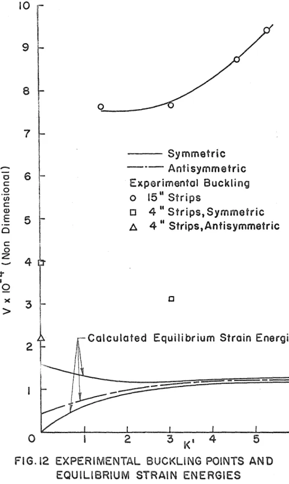
Experimental Buckling Points and Equilibrium S t r a i n Energies
Page 35 35 36 36 37 37 3 8 39 40 4 1 4 1 42 42 43 4 3 44 4 4 4 5 46 46
1
I. INTRODUCTION
The s t a t i c and dynamic behavior of shallow a r c h e s i s of m u c h i n t e r e s t to the engineer, a s shallow a r c h e s r e p r e s e n t one of the
s i m p l e s t types of nonlinear s t r u c t u r e s which exhibit the dynarnic buck- ling phenomenon, a f e a t u r e which i s common to m o r e complex shell s t r u c t u r e s . The complete, t i m e -dependent equation of motion f o r the shallow a r c h i s given by a nonlinear p a r t i a l differential equation to which a n exact solution h a s not yet been found. If the time-dependent t e r m s a r e ignored, the s t a t i c equation of equilibrium r e s u l t s , which m a y be solved exactly f o r various types of loadings and boundary
conditions (Refs. 1 and 2 ) . However, if one wishes to t r e a t the dynarn- i c loading c a s e , one m u s t r e s o r t to e n e r g y methods, o r n u m e r i c a l o r analogue techniques for solving the complete equation of motion.
In p a r t i c u l a r , the dynamic buckling ( o r dynamic snap through) phenomenon h a s a t t r a c t e d attention. Dynamic buckling m a y b e s t be defined a s a l a r g e i n c r e a s e in displacement resulting f r o m a v e r y s m a l l i n c r e a s e in the magnitude of a n applied, time-dependent, load.
The load a t which t h i s i n c r e a s e in displacement o c c u r s i s known a s the dynamic buckling load. This behavior h a s been analyzed by Hsu
(Ref. 3 ) using a n energy argument. He showed that a sufficient condi- tion for the possibility s f dynamic buckling to exist i s that the s y s t e m under consideration p o s s e s s a t l e a s t one stable e q u i l i b r i m position o t h e r than the original unloaded position,
The dynamic buckling o f a simply supported a r c h was f i r s t investigated by Hoff and B m c e (Ref. 4). A r c h e s with clamped ends
w e r e considered by Humphreys (Ref. 5) and Cheung (Ref. 6 ) , among o t h e r s . It m a y be noted that both the simply supported and clamped boundary conditions r e p r e s e n t the limiting c a s e s of a n a r c h whose ends a r e elastically r e s t r a i n e d in rotation. If K i s the rotational spring
constant, then K = 0 gives the simply supported boundary conditions, and K 4 cx, gives the clamped conditions. It was thus thought worth- while to investigate the dynamic buckling behavior of a n a r c h with
elastically r e s t r a i n e d ends. This t h e s i s p r e s e n t s the r e s u l t s of that investigation.
F i r s t , a s e r i e s of experiments w e r e conducted on a r c h e s subjected to unifo rrnly distributed impulsive loadings with the a f o r e mentioned boundary conditions. The r e s u l t s a r e compared to the
c r i t i c a l loads predicted by H s u ' s c r i t e r i a .
Secondly, s o m e qualitative f e a t u r e s of t h e potential energy function of the a r c h a r e discussed. It h a s been shown that dynamic buckling of a n impulsively loaded clamped a r c h in the s e n s e of Hsu i s impossible (Ref. 7 ) . However, dynamic buckling i s possible f o r the simply supported a r c h . This suggests that t h e r e e x i s t s s o m e value of rotational spring constant above which dynamic buckling m a y not occur. T h i s i s shown by a t h e o r e t i c a l argument t o actually be the c a s e , and a n e x p r e s s i o n for t h i s c r i t i c a l value i s given.
11. DESCRIPTION O F EXPERIMENT A. Description of Explosive
Impulsive loading was achieved experimentally by u s e of the explosive s i l v e r acetylide- s i l v e r n i t r a t e (Ag2C2"AgN03). This cornpound yields the low impulse levels n e c e s s a r y f o r a n experiment of t h i s type and i s a l s o relatively safe to handle.
The method of p r e p a r a t i o n of the explosive i s discussed in r e f e r e n c e 8. The explosive i s b e s t s p r a y deposited, and the method of spraying i s d e s c r i b e d in r e f e r e n c e s 8 and 9. In this c a s e , the s p r a y was deposited on 0. 002 in. thick s t r i p s of Mylar of the d e s i r e d length.
After drying, the s t r i p s could be conveniently laid on the surface to be loaded.
Silver -acetylide
-
s i l v e r n i t r a t e i s light sensitive, and detona- tion was achieved by m e a n s of a nonexpendable Xenon flash tube with a 10 in, parabolic reflector. By examination of the Mylar s t r i p sa f t e r firing, it was found that detonation o c c u r r e d n e a r l y simultaneous- l y a t s e v e r a l points d i r e c t l y beneath the f l a s h tube. Ignition then
proceeded outward f r o m t h e s e points. Cheung (Ref. 6 ) h a s shown that the speed of propagation of the explosion i s such that the resulting impulse m a y be considered a s essentially uniform, even though
uniform ignition o v e r the explosive surface i s not realized. Reference 6 a l s o gives a m o r e complete description of the f l a s h tube apparatus.
In o r d e r to verify previously obtained values of impulse p e r unit weight of explosive, a s e r i e s of t e s t s w e r e p e r f o r m e d on a b a l l i s t i c pendulum. The explosive f o r t h e s e t e s t s was sprayed onto
possible the explosive s t r i p g e o m e t r y u s e d in the a c t u a l a r c h t e s t s . The value of impulse p e r unit weight of explosive obtained f r o m t h e s e t e s t s a g r e e d v e r y well with that r e p o r t e d by Cheung (Ref. 6 ) , T h i s value i s I/W, = 1 . 7 9 s l u g - i n / s e c - g m .
It should be noted that Cheung s p r a y e d h i s explosive onto a b a r e m e t a l surface. Apparently, then, the Mylar s u r f a c e h a s only a n
insignificant effect on the magnitude of the impulse unit weight obtainable f r o m the explosive. However, it was observed that f o r values of We /A l e s s than about 0.025 g m / i n 2
,
the explosive would propagate only a s h o r t distance f r o m the initial points of ignition, leaving the a r e a a t the ends of the s t r i p unignited. It i s hypothesized that this i s a Mylar effect, a s Cheung obtained complete ignition with values of We/A l e s s than 0,025 g m / i n 2.
A drawback to the technique of using a spray-deposited explosive should be mentioned. Although i t i s possible to obtain f a i r l y uniform s p r a y s and thus uniform loadings, it i s difficult to deposit exactly a given weight of explosive, Thus one m u s t usually s p r a y a number of
s t r i p s to obtain one with a weight close to the d e s i r e d weight.
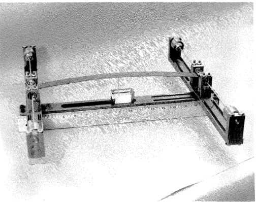
B. Apparatus
1. Arch. The a r c h u s e d in the impulsive loading experiments was formed f r o m a flat piece of spring s t e e l 15 in. long, 1 in. wide, and 1/32 in. thick. The a r c h shape was obtained by buckling t h e s t r i p a s a n E u l e r column, until the d e s i r e d c e n t r a l r i s e was obtained.
F r o m the theory of column buckling, i t i s known that the resulting shape i s a half-sine wave.
5
This i s a simple m e a n s of obtaining a shallow sinusoidal a r c h , and avoids the n e c e s s i t y of rolling the s t r i p to f o r m the d e s i r e d shape.
However, a n initial end t h r u s t , approximately equal to the f i r s t E u l e r buckling load f o r the s t r i p , i s introduced into the s t r u c t u r e . This m u s t accordingly be taken into account i n the t h e o r e t i c a l analysis.
2. Rotational spring and a r c h f r a m e . The rotational s p r i n g s w e r e constructed by attaching t o r s i o n rods to e i t h e r end of the a r c h in
such a way that rotation of the a r c h ends r e s u l t e d in twisting of the r o d s . This was accomplished by securing both ends of the r o d i n d r i l l chucks so that no rotation of the rod ends was possible. Two s m a l l plates w e r e then s c r e w e d down o v e r the c e n t e r of the rod, and one end of the a r c h i n s e r t e d between the two plates, s o that the a r c h end
r e s t e d against the rod. Two s e t s c r e w s in the top of one of the plates w e r e then tightened to hold the a r c h in place. The c e n t e r of each t o r s i o n rod was knurled, so a s to reduce the possibility of slippage between the rod and the clamped plates. This a r r a n g e m e n t i s depicted in F i g u r e 1.
To avoid l a t e r a l bending of the t o r s i o n rods due to a r c h end t h r u s t , the rods w e r e supported b y passing t h e m through Torrington 4 N B C 6 1 2 Z P needle bearings placed immediately to either side of the clamped plates. The bearings w e r e p r e s s e d into m e t a l blocks which w e r e then bolted to the a r c h f r a m e , a heavy s t e e l s t r u c t u r e . The b e a r i n g s a l s o s e r v e d to r e s t r a i n the a r c h ends f r o m motion. An o v e r a l l view of the a r c h f r a m e , with t o r s i o n r o d s and a r c h in place, i s given in F i g u r e 2a, b,
3 . Spring stiffnesses. The t o r s i o n rods w e r e made f r o m lengths of s t e e l rod. By varying the length and d i a m e t e r of the rod, a f a i r l y wide range of rotational spring constants could be obtained.
It should be noted h e r e that the d r i l l chucks could be moved along the length of the c r o s s a r m s , allowing the u s e of r o d s of different lengths.
A f t e r manufacturing the rods, t h e i r rotational spring constants w e r e m e a s u r e d experimentally by placing the rods in position i n the a r c h f r a m e . They w e r e then subjected to a known moment applied through the clamping plates and t h e resulting angle of twist m e a s u r e d .
Rods having four different rotational spring constants w e r e u s e d in t h e impulsive loading experiments. These had values of K = 8 5 . 0 , 75.0, 4 8 . 8 , and 22.5 in-lbs / r a d .
The t o r s i o n a l stiffnesses of the r o d s w e r e a l s o calculated using the standard t o r s i o n a l t h e o r y for c i r c u l a r b a r s . F o r t h e stiffest
spring, t h i s gave a value of stiffness 15 /o above that o b s e r v e d 0
experimentally. The a g r e e m e n t between t h e o r y and experiment became b e t t e r with decreasing stiffness. It i s felt that t h i s d i s c r e p - ancy i s due to s o m e twisting of the rod within the clamped p l a t e s , the
rods not being held completely clamped. However the experimental values of t o r s i o n a l stiffness w e r e quite repeatable, so t h i s occasioned no difficulty.
It was found that the a r c h f r a m e p o s s e s s e d a nonnegligible amount of flexibility in the axial, o r horizontal direction. The stiff- n e s s of the f r a m e in the axial direction was accordingly m e a s u r e d experimentally by applying a known f o r c e o v e r the range of expected a r c h end t h r u s t s and measuring the deflection. In this m a n n e r , i t
7
was determined that the f r a m e had a n effective a x i a l spring constant of approximately 16, 600 l b s l i n . T h i s was then included in the
t h e o r e t i c a l a n a l y s i s by adding a n axial spring a t one end of the a r c h . 4. M e a s u r e m e n t of a r c h deflection. A m e a s u r e m e n t of the a r c h deflection under loading was obtained by soldering a long needle to the underside of the a r c h a t i t s c e n t e r . %'-hen the a r c h deflected, the needle p i e r c e d a s e r i e s of t i s s u e s t r i p s . An examination of the t i s s u e s a f t e r the experiment was o v e r then gave a n indication of the total deflection of the center of the a r c h . Since the t i s s u e s w e r e
spaced 0.2 in. a p a r t , only a n approximate m e a s u r e could be obtained However, this i s not felt to be a s e r i o u s drawback. A photograph of the s m a l l f r a m e u s e d to hold the t i s s u e s t r i p s i s given i n F i g u r e 3 .
111. THEORETICAL ANALYSIS
A . Equations of Motion
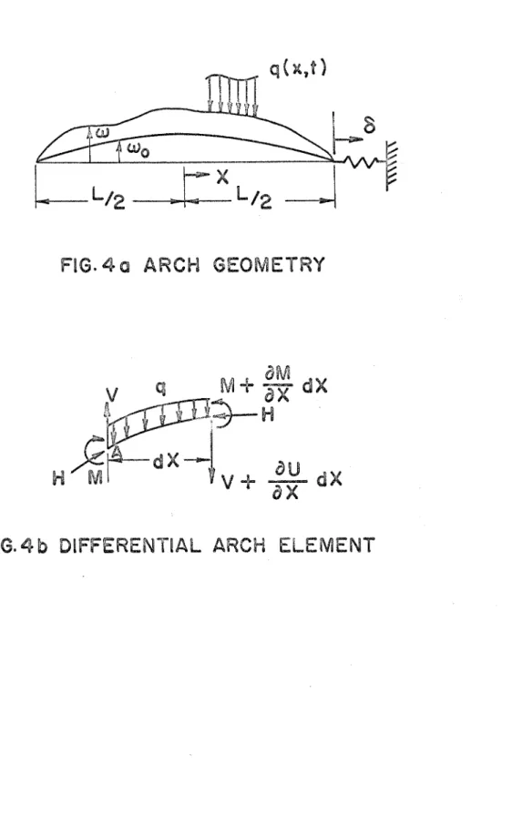
The a r c h geometry to be considered i s shown in F i g u r e 4a.
I t i s a s s u m e d that due to the shallowness of the a r c h , the axial load H m a y be considered constant throughout the a r c h . Under this
assumption, the equation of motion m a y be derived by considering the equilibrium of a differential element of the a r c h , shown in F i g u r e 4b.
Summing f o r c e s in the vertical direction
and taking moments about point A,
Combining t h e s e equations
Note h e r e that M i s the total bending moment p r e s e n t in the a r c h . Thus f r o m standard b e a m theory
a w
2 M = EI-ax
2The end t h r u s t i s given by
and 6 i s the deflection of the axial spring. Thus
Also, i f a r e p r e s e n t s the spring constant of the axial spring,
Combining t h e s e two e x p r e s s i o n s gives
and t h e r e f o r e
Substitution of ( 2 ) and (3) into ( 1 ) then give the final equation of rnotion
It m a y be noted that t h e r e i s s o m e difference between (4) and the equation of motion a s it i s usually p r e s e n t e d i n the l i t e r a t u r e ( i n p a r t i c u l a r , r e f e r e n c e 1, where this equation was obtained f o r the f i r s t
4 2
t i m e ) . Usually, the t e r m - E I
a
wo/ax4-
Hoa
wo /ax2 would be added to the left-hand side of (4). However the a r c h under consider- ation i s a s s u m e d to have obtained i t s shape a s the r e s u l t of the buckling of a flat s t r i p . Thus f o r t h i s c a s e ;I t will l a t e r be shown that, by utilizing a n e n e r g y analysis to t r e a t the c a s e of buckling under a n impulsive load, only the s t a t i c
equilibrium positions of the a r c h under z e r o load need be considered.
Thus in (4), the t i m e dependency vanishes, and q = 0. ( 4 ) then be comes
where H i s given by (3).
The analysis f r o m t h i s point will be s i m i l a r to that p r e s e n t e d by Vahidi i n r e f e r e n c e 2.
F i r s t equations (5) and ( 3 ) a r e written in t e r m s of nondimen- sional v a r i a b l e s by making the following substitutions :
( 5 ) thus becomes
and ( 3 ) becomes
F o r a sinusoidal a r c h with the coordinate s y s t e m a s indicated in Figure 4a, yo = r cos
5
Also, for the p a r t i c u l a r c a s e under consideration, H i s just
0
equal to the f i r s t E u l e r buckling load f o r the s t r i p , and t h e r e f o r e S = 1.
The solutions of ( 6 ) d e s c r i b e the equilibrium positions of the a r c h , and, f o r a n y e q u i l i b r i u m p o s i t i o n , w i l l b e a constant. If we thus a s s u m e
p
to have a known constant value, the solution to ( 6 ) m a y immediately be found to be:y = A1 s i n
P 5 +
Az cosP 5 +
A jE, +
A4 (8w h e r e A1, A2, A j a n d A4 a r e constants to b e d e t e r m i n e d f r o m t h e boundary conditions.
F o r t h e c a s e of a n a r c h with r o t a t i o n a l end r e s t r a i n t s ( s p r i n g constant = KJ, t h e boundary conditions in nondirnensional f o r m a r e :
Ti- Ti-
Y ( -
Z)
= Y ( ~ ) = 0w h e r e K ' = K L ITEI
T h e s e t h e n give f o u r equations f o r t h e f o u r u n d e t e r m i n e d constants A A2, A and A4.
1 ' 3
PTi- PTi-
A sin-
+
A ~ C O S - Ti-A31 2 2
+2
+ A 4 = 0PTi-
P r
3.1 2 2 2 A f A 4 = 0
- A s i n - t A c o s -
- 2
PTi- @Ti- 2 PTi- 2
PTi-=o
- K t ( - r + A I P c o s - t A Psin7
+
A )+ A I P s i n T-
A2P C O P2 2 3 2
t
9d) Now s u b t r a c t ( 9 c ) f r o m ( 9 a ) , and add (9b) to (9b) , The r e s u l t isS i m i l a r l y , add ( 9 c ) to (9a) and s u b t r a c t (9d) f r o m (9b) to obtain
A2(K1P s i n
+ +
2 cosq) -
Kf r = 0 (1 l b )Note that (10a, lob) contain only the a n t i s y m m e t r i c components of the a r c h deformation, while (1 l a , 1 l b ) contain only the s y m m e t r i c
components. Solving ( 1 la , 1 l b ) gives
A2 = K' r
P P.-
K'psin - 2
+
cos-
2
Rewriting (lOa, l o b ) ,
P r
A s i n - + - A = O
1 2 2 3
2
P.- 6.-
A1(P s i n
-
K'P cosT ) -
K 1 A 3 = 0Two possibilities exist h e r e .
i. A1 = A 3 = 0, which implies that the deflected a r c h shape i s s y m m e t r i c .
ii. A l , A3 f 0, which implies that the determinant of the m a t r i x of coefficients vanishes, i. e.
pTr Tr 2 pl-r
P r
-K'sin- 2
+ -(P
2 sin- 2-
K'P C O S -) 2 - 0This equation i s a transcendental equation f o r
P.
It i s interesting to note that this equation always h a s solutions, even for the c a s e K' -, CQ. In t h i s instance, (14) becomesP r
- PTrtan - - - 2 2
which does indeed have solutions. Note a l s o that for A12 A3
#
0, we cannot yet obtain explicit r e p r e s e n - tations f o r A1 and A3, but only a relation between the two. F r o m (13a), this relation i sA = - A 2 s i n &
3 T r l 2
Recall we a s s u m e d a t the s t a r t that
P
had some knownconstant value which, however, was not specified. Apparently, then, another relation i s needed in o r d e r to completely d e t e r m i n e the
equilibrium s t a t e s . This relation i s supplied by requiring ( 7 ) to b e satisfied. F o r if we substitute the e x p r e s s i o n s f o r y and y into
0
( 7 ) , we obtain
1 2 2 2 2 pl-r
PTr
PTr 2 2 PTr$3
-
1 ) -+;
A lP(-Z +
s i n - cos -)+--AP(- -
sin$ cos -)P r
2 2 T r 2 2 2
15
(16) i s called the "constraint equation" by Vahidi. With the inclusion of (16), the p r o b l e m i s completely determined.
In the i n t e r e s t of c l a r i t y , the method of obtaining solutions f o r the s e p a r a t e c a s e s A l = A = 0 and A A
i
0 will now be outlined.3 1' 3
i. A = A = 0 ( s y m m e t r i c c a s e )
1 3
In this c a s e the deflected equilibrium position i s , f r o m ( 8 ) ,
where A2 and A4 a r e given by (12a) and (12b) respectively. Noting that A2 and A4 a r e functions of
p
and known a r c h p a r a m e t e r s ,(12a, 12b) m a y be substituted into (16) to obtain a transcendental equation which m a y then be solved f o r
p.
The roots of t h i s equation m a y then besubstituted into (17) to obtain e x p r e s s i o n s for the equilibrium positions of the a r c h .
11.
. -
A1, A $ 0 ( a n t i s y m m e t r i c c a s e ) 3In t h i s c a s e (14) m u s t be satisfied. (14) i s another transcendental equation in
p,
the roots of which d e s c r i b e the equilibrium positions of the a r c h . Knowing the equilibrium values ofP,
A2 andA 4 m a y be calculated. However, A1 and A 3 a r e s t i l l indeterminant. Knowing
P,
we m a y u s e (15) and ( 16) to solve for A1 and A3. Putting ( 15) into(16) gives
-
-
2p(-2- P r +
s i n 2P r
cos FIT- 7
8 s i n 2 &=2 - IT
'K 2
Thus
The
-
t sign simply m e a n s that no a n t i s y m m e t r i c orientation i s p r e f e r r e d , Note t h e r e e x i s t s a possibility that (20) m a y p o s s e s s no r e a l roots.This possibility will be d i s c u s s e d l a t e r .
A digital computer p r o g r a m was written to solve the two transcendental equations and to calculate the deflected equilibrium positions f o r both the s y m m e t r i c and a n t i s y m m e t r i c c a s e s . A plot of s o m e of the lower equilibrium values of
P
vs. K t obtained by this p r o g r a m i s given in F i g u r e 5,B. Stability under Impulsive Load
To c h a r a c t e r i z e the stability of the a r c h under a n impulsive load, the s t r a i n energy p r e s e n t in any equilibrium position m u s t f i r s t be calculated. The difference in s t r a i n energy f r o m the undeforrned
s t a t e i s given by
w h e r e
N o w define a nondirnensional e n e r g y by
Substituting (22) into (21) and using (23) gives
Now w r i t e
U = U1
+ u2 +
U3+ u4
- - n A ' p 3 [ IT pn
+
s i n pn]
- r (271by using (8) and the relation yo = r cos
5
- - Kn ~2 2
C O S ~ @ + ~ X ~ P
A 2 ~ 2~ 2 s i n 2 p n Z + 2 A 3 219
Now that a n e x p r e s s i o n for the s t r a i n energy h a s been derived, we m a y apply Hsu' s c r i t e r i o n to the c a s e of impulsive loading to
determine the stability of the a r c h .
Consider a uniformly distributed impulsive load given by
q ( t ) = B 6 ( t ) ( 3 0 )
The initial velocity of the a r c h will then be
&
= B/,-,A and i t s initial energy i sNow H s u ' s stability c r i t e r i o n i s that be l e s s than s o m e c r i t i c a l value
T'.
If>
V-* ,
then the possibility of dynamic snap throughe x i s t s ,
4,
In o r d e r to determine
V.''
for the a r c h , consider F i g u r e 6, which depicts a n energy surface for the a r c h with no applied load.
H e r e q r e p r e s e n t s some s y m m e t r i c component of the deflected 1
shape, and q s o m e a n t i s y m m e t r i c component, The contours 2
r e p r e s e n t e q u i - s t r a i n energy c u r v e s , A d i a g r a m of this s o r t for the a r c h was f i r s t p r e s e n t e d by Hoff and Bruce in r e f e r e n c e 4.
F r o m the condition that equilibrium positions correspond to a n e x t r e m u m on the energy s u r f a c e , we s e e that, within the simplified representation of the diagram, t h e r e a r e only four equilibrium posi- tions available a p a r t f r o m the initial position (actually t h e r e m a y be m o r e , depending on the initial a r c h r i s e , but t h e s e have no meaning in
t h e p r e s e n t d i s c u s s i o n ) . The two positions with q2 components a r e saddle points and a r e t h u s unstable. One of t h e positions on t h e q 1 a x i s is a t t h e top of a "hill" a n d i s unstable; t h e o t h e r i s a t t h e bottom of a d e p r e s s i o n and i s a stable equilibrium position.
Now i t is known that no m a t t e r how m a n y equilibrium positions t h e a r c h p o s s e s s e s under z e r o load, t h e r e m a y e x i s t only one s t a b l e position a p a r t f r o m the initial position. This is the "snapped throught' position, i n which the a r c h undergoes a r e v e r s a l of c u r v a t u r e along m o s t of i t s length. T h i s position i s m a d e up of s y n m e t r i c deflection
components only, a n d m a y be identified with t h e d e p r e s s i o n in t h e e n e r g y s u r f a c e .
We m a y c o n s i d e r the a r c h t o d e s c r i b e a t r a j e c t o r y o v e r t h e e n e r g y s u r f a c e in q
-
q2 space. Now t h e effect of the impulsive load i s to i m p a r t a n initial e n e r g y to t h e a r c h . If enough e n e r g y i s i m p a r t e d to t h e a r c h , t h e t r a j e c t o r y will be able to c r o s s o v e r the r i s e i n the e n e r g y s u r f a c e separating t h e o r i g i n a l unloaded equilibriwn.position f r o m t h e snapped through equilibrium position. When t h i s happens, dynarnic buckling i s s a i d t o have o c c u r r e d . However, i f t h e a r c h does not have enough e n e r g y to c r o s s t h e r i s e , t h e t r a j e c t o r y will always r e m a i n in t h e vicinity of t h e o r i g i n a l position.
F r o m the definition of
O*
a s that initial e n e r g y above which.I.
dynamic buckling m a y o c c u r , it i s e a s y t o s e e that
V*''
i s just equal to t h e e n e r g y a s s o c i a t e d with t h e saddle points, a s t h e s e a r e the pointshaving the lowest e n e r g i e s on the r i s e separating t h e two s t a b l e equi- l i b r i u m positions. I t is a l s o e a s y to s e e how t h i s s a t i s f i e s the definition of dynamic buckling given i n t h e Introduction. Suppose t h e a r c h follows
2 1
a t r a j e c t o r y which p a s s e s through one of the saddle points. Then if t h e
-
<<a r c h h a s a n initial e n e r g y V
,
the t r a j e c t o r y will eventually c o m e to r e s t a t t h e saddle point i n unstable equilibrium, taking a n infinitely long t i m e to do so. However if t h e a r c h h a s a n initial e n e r g y9
=8" + A T ,
t h e n it will have sufficient e n e r g y so t h a t t h e t r a j e c t o r y will c r o s s t h e saddle point and p r o c e e d down t h e o t h e r s i d e of t h e r i s e . Thus a n infinitesimal i n c r e a s e i n load (and thus initial e n e r g y ) h a s produced a finite i n c r e a s e in displacement.If the t r a j e c t o r y was t o p a s s o v e r s o m e p a r t of t h e r i s e o t h e r than the saddle points, m o r e e n e r g y would be r e q u i r e d than t h a t n e c e s s a r y to c r o s s a t t h e saddle points. Thus
O*
i s a n e c e s s a r ycondition f o r dynamic buckling.
It should be noted that, f o r H s u ' s c r i t e r i o n to be applicable, t h e r e m u s t e x i s t a t l e a s t one s t a b l e e q u i l i b r i u m position o t h e r than the undeflected position. If the undeflected position i s the only stable equilibrium position, then a l l t r a j e c t o r i e s which s t a r t out f r o m t h i s point on t h e e n e r g y s u r f a c e will eventually r e t u r n to the s a m e point.
Thus dynamic buckling in the s e n s e of Hsu i s not possible. T h i s , of c o u r s e , implicitly a s s u m e s that t h e a r c h will n e v e r come to r e s t in a n unstable equilibrium position.
A plot of s t r a i n e n e r g y v s . K ' i s given in F i g u r e 7 , f o r r = 3 9 . 8 f o r the f i r s t t h r e e equilibrium positions. I t c a n be s e e n t h a t t h e f i r s t s y m m e t r i c position h a s t h e lowest energy. This c o r r e s p o n d s t o the stable snapped through equilibrium position. The next highest e n e r g y i s a s s o c i a t e d with t h e f i r s t a n t i s y m m e t r i c position, which c o r r e s p o n d s to the saddle points, o r
B"'.
Effect of Increasing Torsional Spring Stiffness
It was stated previously that, in o r d e r f o r Hsu's stability c r i t e r i o n to b e applicable, the a r c h m u s t p o s s e s s a t l e a s t one other stable equilibrium position other than the original unloaded position.
If such i s not the c a s e , then the a r c h m u s t always be stable in the s e n s e of Hsu.
Now the simply supported a r c h i s known to have a stable equi- l i b r i u m position other than the original unloaded position. Thi s i s the
snapped through position. Contrariwise, i t h a s been shown by Vahidi (Ref. 7 ) and confirmed experimentally by Cheung (Ref. 6 ) that the clamped a r c h h a s no stable equilibrium position other than the original position. This then suggests that t h e r e e x i s t s s o m e c r i t i c a l value of
rotational spring constant above which the a r c h p o s s e s s e s only one stable equilibrium position, the undeflected one, Above this c r i t i c a l value, dynamic buckling in the mathematical s e n s e m a y not occur.
It i s suspected, t h e r e f o r e , that a t some point the f i r s t
s y m m e t r i c (snapped through) position l o s e s i t s stability and becomes unstable. The mechanism causing this to occur m a y be deduced by considering F i g u r e 7. With increasing spring stiffness, the s t r a i n energy curves f o r the f i r s t s y m m e t r i c and f i r s t a n t i s y m m e t r i c equi- librium positions tend to run together until they m e r g e . By then looking a t the energy surface in F i g u r e 6, it can be seen that this i m p l i e s that the two saddle points a r e merging in along the q 2 a x i s towards the d e p r e s s i o n representing the f i r s t symmetric position.
When this m e r g e r becomes complete, the f i r s t s y m m e t r i c position will become a saddle point, and will thus l o s e i t s stability.
At t h i s point, the a n t i s y m m e t r i c equilibrium positions will have ceased to exist. In o r d e r to determine the value of rotational spring constant a t which t h i s o c c u r s , consider equation ( 2 0 ) , which is
w h e r e
- - Z P (?
P r
4- s i n - pn cos -) Pn- -T
8 s i n 2&
D2 - 7T 2 2
Sh
2
p
i s a s s u m e d to have been determined f r o m equation (14).Consider f i r s t the expression f o r D2. F r o m equation (14) and F i g u r e 5 it can be s e e n that the lowest possible value of
P
f o r anti- s y r m e t r y i sP
= 2. This simply c o r r e s p o n d s to a n end t h r u s t equal to the second E u l e r buckling load f o r the s t r i p when K ' = 0. Thus D2 will always be positive.Now consider the expression f o r D l = If a n t i s y m m e t r i c equi- l i b r i u m positions a r e to exist, D m u s t be negative. F o r a r c h e s with
1
any appreciable r i s e , r 2 will be relatively l a r g e (approximately 1600 f o r the a r c h used in the experiment). Thus f o r M' s m a l l enough,
D l will indeed be negative, and a n t i s y m m e t r i c solutions will exist.
The value of K s a t which a n t i s y m m e t r i c positions will c e a s e to exist m a y be found by setting D - 0 . Thus
1 -
Substituting f o r A2 f r o m equation (12a) gives
P r
2P r
2 r ( K I P s i n-
2+ 6
cos-Z-)
This equation can be put in t e r m s of 63 alone by solving equation (14) f o r K 1 . Thus
- Z' 2 s i n - P r
Kt = 2
- "P
cos- P r -
sin2 2
p.-
2
Substituting (33) into ( 3 2 ) gives a transcendental equation f o r
P.
Thelowest root of t h i s equation will then give the c r i t i c a l value of KIP when substituted back into ( 3 3 ) . The lowest value of m u s t be used, a s this root will be the l a s t to d i s a p p e a r with increasing K ' . This m a y be realized by considering the equation f o r
D2.
The fact that only the originai position e x i s t s f o r the clamped a r c h implies that a l l s y m m e t r i c positions will likewise disappear with increasing K ' . When this o c c u r s , equation (16) will no longer p o s s e s s a n y r e a l roots.
25
IV. RESULTS
As stated previously, the a r c h employed in the experimental p a r t of the work had a c e n t r a l r i s e of 23 /32 in. It was 15 in. long, 1 in. wide, and 1/32 in. thick. F o u r different stiffnesses of t o r s i o n
r o d s w e r e used, having experimentally m e a s u r e d spring constants of K = 85.0, 75.0, 48.8 and 22.5 i n - l b s / r a d , corresponding to non- dimensional values of K' = 5.29, 4.67, 3.04 and 1.40 respectively.
An axial spring with a spring constant of 16, 600 l b s / i n was a l s o included.
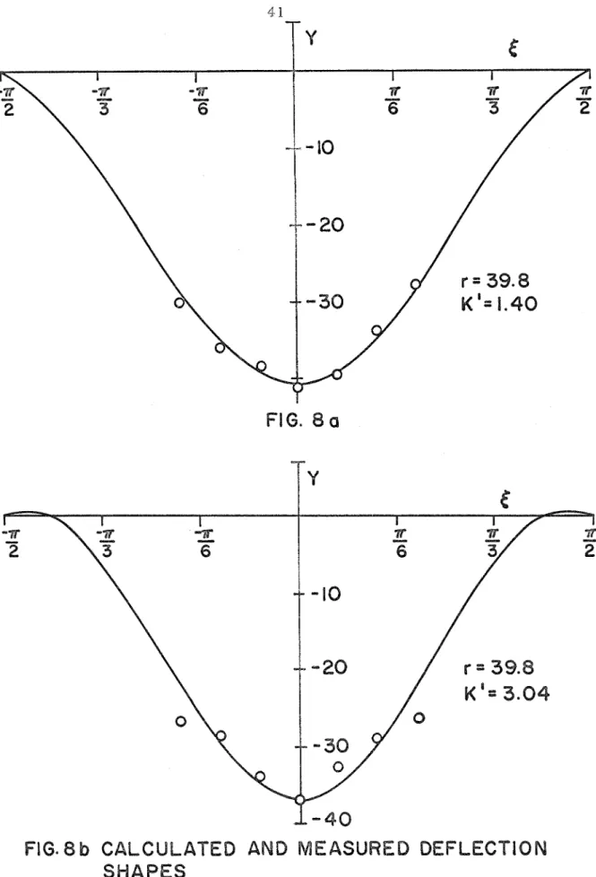
1. Deflectionshapes
In o r d e r to s e e how closely the t h e o r y p r e d i c t e d the s t a t i c equilibrium a r c h s h a p e s , m e a s u r e m e n t s w e r e m a d e of the v e r t i c a l deflection of the a r c h in the snapped through position. The m e a s u r e - m e n t s w e r e m a d e a t a number of stations n e a r the a r c h center using a p a i r of dividers. The r e s u l t s a r e p r e s e n t e d in F i g u r e s 8a-d. It can b e s e e n that in m o s t c a s e s the a g r e e m e n t between the theoretically predicted deflection c u r v e s and the experimentally m e a s u r e d values i s quite good.
Along with t h i s , a n attempt was m a d e to d e t e r m i n e e x p e r i - mentally that c r i t i c a l value of rotational spring constant above which a stable snapped through position could not exist. It was found that f o r K = 100 in-lbs / r a d , the a r c h would not r e m a i n in the snapped through position, but tended to spring back into i t s original shape when
r e l e a s e d . Since a stable snapped through position was achieved for K = 85.0 i n - l b s / r a d , the c r i t i c a l value i s s u r m i s e d to lay somewhere between K = 85- 100 in-lbs / r a d .
Using equations (32), ( 3 3 ) the t h e o r e t i c a l c r i t i c a l value was calculated. This gave K = 633 i n - l b s / r a d . The wide discrepancy between the t h e o r e t i c a l and experimental values will be d i s c u s s e d l a t e r .
2. Uniform Impulsive Loading
The impulsive loading experiments w e r e conducted by laying 15" s t r i p s of explosive-sprayed Mylar onto the a r c h to be loaded.
T h e s e w e r e then ignited with a zenon f l a s h tube, a s d e s c r i b e d
previously, P l o t s of a r c h c e n t r a l deflection vs. total irnpulse applied to the a r c h a r e given in F i g u r e s 9a-d and 10. It m a y be observed that the experimental points exhibit a good deal of s c a t t e r . This i s in p a r t due to the i n a c c u r a c i e s inherent in the deflection m e a s u r i n g apparatus.
Another s o u r c e of e r r o r a r i s e s f r o m the fact that the a r c h c e n t r a l deflection m a y not in a l l c a s e s give a good indication of the magnitude of the a r c h response. Cheung (Ref. 6 ) , for example, u s e s a s a
m e a s u r e of a r c h response the a r e a between the deformed and un- deformed a r c h shapes.
It m a y be s e e n f r o m the plots, however, that f o r some r a t h e r n a r r o w range of impulse level, t h e r e i s a l a r g e jump in a r c h c e n t r a l deflection. T h i s type of response i s typical of the dynamic buckling phenomenon.
In o r d e r to make a comparison with theory, dynamic buckling was said to have o c c u r r e d experimentally when the c e n t r a l a r c h
deflection reached a value of 0 . 6 in. Corresponding values of total impulse w e r e then r e a d f r o m Figure 10. These a r e plotted a s total initial energy i m p a r t e d to the a r c h in Figure 12. Also plotted h e r e
27
a r e the s t r a i n e n e r g i e s corresponding to the f i r s t t h r e e equilibrium positions (those having the lowest values of
P).
Theoretically, thec u r v e corresponding to the f i r s t a n t i s y m m e t r i c position r e p r e s e n t s a lower bound on the initial energy r e q u i r e d for buckling. It can b e s e e n that the experimental values a r e i n fact quite a bit higher than t h i s
curve.
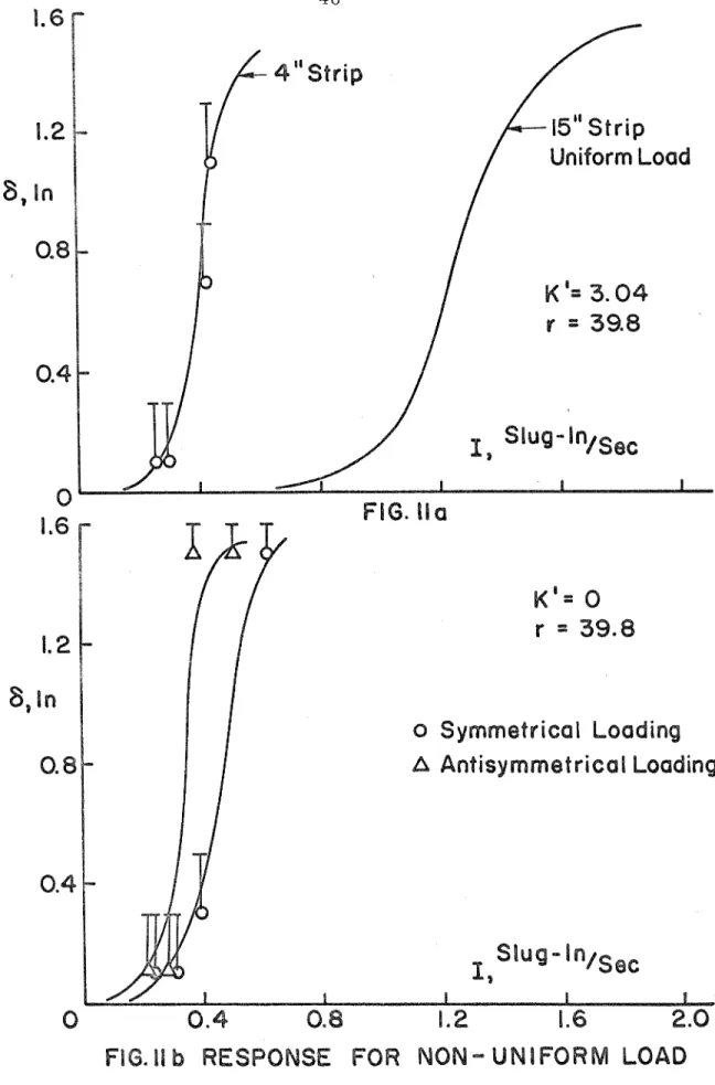
3 . Experiments with Nonuniform Loadings
In addition to conducting t e s t s with uniformly-distributed impulsive loading s , s e v e r a l experiments w e r e m a d e with nonuniform loadings. Instead of using 15 in. s t r i p s of explosive which covered the length of the a r c h , s h o r t e r 4 in. s t r i p s w e r e u s e d which loaded only a portion of the a r c h length.
F o r the f i r s t of these t e s t s , the 4 in. s t r i p s w e r e placed along the c e n t r a l section of a n a r c h having K = 48.8 i n - l b s / r a d . The
deflection response vs. total applied impulse i s plotted in F i g u r e 11, along with the r e s u l t s for the s a m e K using 15 in. s t r i p s . It m a y be
s e e n that much l e s s total impulse was n e c e s s a r y to buckle the a r c h with the 4 in. s t r i p than with the 15 in. s t r i p . Again, a value of
c r i t i c a l impulse was obtained f r o m F i g u r e 11, converted to initial a r c h energy by m e a n s of equations (30) and (31), and plotted in F i g u r e 12.
I t can be s e e n that this value i s much c l o s e r to the theoretically
predicted lower bound than those values obtained by uniform loadings.
F o r the second t e s t , the d r i l l chucks holding the t o r s i o n rods w e r e loosened so that the ends of the a r c h w e r e f r e e to rotate. In this way, it was hoped to approximate simply supported boundary conditions, The 4 in, s t r i p s w e r e then placed alternatively along the c e n t r a l section
of the a r c h , o r a t one-quarter of the length f r o m the end of the arch.
The responses a r e plotted in Figure 12. I t can be seen that the c r i t i c a l impulse for the a r c h loaded along one side i s somewhat l e s s than for the a r c h loaded in the center. This i s to be expected f r o m theoretical considerations, since it was shown previously that an a r c h required l e s s initial energy to buckle in an antisyrnmetric shape than a s y m m e t r i c shape. Loading the a r c h along one side apparently tends to drive the a r c h along a m o r e antisyrnmetric t r a j e c t o r y than would be the case if the a r c h were centrally loaded.
As before, the approximate c r i t i c a l values of total impulse a r e plotted a s initial energy imparted to the a r c h in Figure 12.
2 9
V. DISCUSSION
A t h e o r e t i c a l and experimental investigation of the buckling of a shallow a r c h u n d e r a n impulsive load h a s been c a r r i e d out. E l a s t i c
rotational r e s t r a i n t s w e r e attached to the ends of the a r c h and a n a x i a l spring was included.
1. Deflection Shapes
F r o m the r a t h e r good a g r e e m e n t between the theoretically predicted and experimentally m e a s u r e d deflection shapes ( F i g u r e s 8 a - d ) , i t m u s t be concluded that the s t a t i c equilibrium positions of the unloaded a r c h a r e well c h a r a c t e r i z e d by the analysis p r e s e n t e d in Section 111.
An experiment was p e r f o r m e d to determine that c r i t i c a l value of rotational spring constant above which stable snapped through positions ceased to exist. This value was found to l i e somewhere in the range K = 8 5 - 1 0 0 i n - l b s / r a d . On the o t h e r hand, a t h e o r e t i c a l a n a l y s i s predicted a c r i t i c a l value of K = 633 i n - l b s / r a d . The wide discrepancy between t h e s e two values m a y be explained by considering F i g u r e 7 , It i s observed that although the s t r a i n energy c u r v e s f o r the f i r s t s y m m e t r i c and f i r s t a n t i s y m m e t r i c positions m e r g e into one a n o t h e r , they do so v e r y slowly. Consequently t h e r e e x i s t s a consider able range of K f o r which these two c u r v e s l i e quite closely together.
The f i r s t s y m m e t r i c position corresponds to the stable snapped through position, and the f i r s t a n t i s y m m e t r i c position i s unstable.
Thinking in t e r m s of energy s u r f a c e s , t h i s m e a n s that the d e p r e s s i o n in the s u r f a c e containing the f i r s t s y m m e t r i c position i s v e r y shallow.
Thus any s m a l l d i s t u r b a n c e m a y suffice to j a r the a r c h f r o m t h i s d e p r e s s i o n and into a n unstable configuration. It goes without saying t h a t the physical world i s full of such d i s t u r b a n c e s . T h e r e f o r e , t h e
stability of the snapped through equilibrium position will p r a c t i c a l l y e x i s t only f o r m u c h s m a l l e r v a l u e s of rotational s p r i n g constant than would be indicated theoretically. A l s o , and p o s s i b l y m o r e importantly, t h e a r c h i s a n i m p e r f e c t physical s t r u c t u r e , and t h i s will a l s o r e d u c e t h e c r i t i c a l value of rotational s p r i n g constant.
It was found that the inclusion of a n a x i a l s p r i n g in the t h e o r e t i - c a l a n a l y s i s affected t h e equilibrium positions and t h e s t r a i n e n e r g y of t h e s e positions to only a negligible extent. The r e a s o n f o r t h i s m a y be m a d e c l e a r b y considering equation (16). The effect of t h e a x i a l s p r i n g e n t e r s only through t h e f i r s t t e r m i n t h e equation. F o r t h e a x i a l s p r i n g constant of 16, 600 l b s - i n , C i s a p p r o x i m a t e l y equal to 0.2. Thus f o r low values of 63, the f i r s t t e r m i s completely dominated b y the r 2 ten-n, which is approximately 1, 600. T h e a x i a l s p r i n g t e r m s i m i i a r l y plays little p a r t in the s t r a i n e n e r g y e x p r e s s i o n . The effect of the axial s p r i n g will only be felt f o r v e r y soft a x i a l s p r i n g s o r f o r low initial a r c h r i s e s .
2. Uniform Impulsive Loading
An a r c h with different values of rotational s p r i n g constant was subjected to a s e r i e s of uniformly d i s t r i b u t e d impulsive loadings. T h e r e s p o n s e c u r v e s a r e plotted together i n F i g u r e s 9a-d and 10. I n c r e a s - ing t h e value of t h e rotational spring constant i s s e e n t o have only a slight effect on the c r i t i c a l impulsVe r e q u i r e d f o r buckling. Generally,
3 1
however, the g r e a t e r the spring constant, the higher the level of impulse r e q u i r e d for buckling,
Also, no significant change in the shape of the response curve can be noted with increasing spring constant. No experiments w e r e conducted using rotational spring constants f o r which stable snapped through positions could not be achieved. Cheung, however, in
r e f e r e n c e 6 p r e s e n t e d response c u r v e s for a clamped a r c h under a uniform impulsive load. The shape of t h e s e c u r v e s a r e somewhat
f l a t t e r than those in Figure 10, but t h e r e i s otherwise no qualitative difference. Cheung
'
s curves s i m i l a r l y d e m o n s t r a t e a significant i n c r e a s e in deflection for a relatively s m a l l i n c r e a s e of applied i m - pulse, which i s a c h a r a c t e r i s t i c of the dynamic buckling phenomenon.This i s an interesting r e s u l t in view of the fact that t h e clamped a r c h cannot exhibit dynamic buckling in the m a t h e m a t i c a l s e n s e of Hsu.
However, since a "dynamic buckling-type" behavior i s exhibited by the clamped a r c h , f o r which K 4 E K ~it i s not s u r p r i s i n g that the ~
response c u r v e s should show little v a r i a n c e f o r values of K which a r e relatively close together.
It should additionally be noted that the u s e of H s u ' s c r i t e r i o n provides a v e r y conservative lower bound on the c r i t i c a l impulse needed for buckling. In actuality, buckling o c c u r r e d a t a n impulse level approximately t h r e e t i m e s a s g r e a t a s indicated by the lower bound.
3
.
Nonunifo rrn LoadingF o r the f i r s t of t h e s e e x p e r i m e n t s , 4 in. explosive s t r i p s w e r e placed on the c e n t r a l portion of a n a r c h with rotational s p r i n g s having
K = 48.8 i n - l b s l r a d , A significant reduction i n t h e t o t a l i m p u l s e n e c e s s a r y to buckle t h e a r c h was noted. A p o s s i b l e explanation i s t h a t loading the a r c h along i t s c e n t r a l portion only tends t o d r i v e t h e a r c h through t h e second s y m m e t r i c equilibrium position. T h e second
s y m m e t r i c position i s c o m p a r a b l e to t h e s h a p e of a column under the t h i r d E u l e r buckling load, t h a t i s , one a n d one-half s i n e waves
s y m m e t r i c about the a r c h c e n t e r . It c a n be s e e n f r o m F i g u r e 7 that f o r K ' = 3 . 04, t h e second s y m m e t r i c position h a s only a slightly h i g h e r e n e r g y than t h e f i r s t a n t i s y m m e t r i c position, which r e p r e s e n t s a lower bound on initial e n e r g y n e c e s s a r y f o r buckling. Thus, i n e s s e n c e , the t r a j e c t o r y of t h e a r c h o v e r t h e e n e r g y s u r f a c e was
"aimed" i n s u c h a m a n n e r a s t o r e d u c e t h e initial e n e r g y r e q u i r e d f o r buckling.
Another e x p e r i m e n t of t h i s type was c a r r i e d out using approxi- m a t e simple support boundary conditions. T h e r e a s o n f o r t h i s was t h a t a t M = 0 , the s t r a i n e n e r g y c u r v e s f o r t h e f i r s t a n t i s y m m e t r i c and the second s y m m e t r i c equilibriunpositions show t h e i r g r e a t e s t difference in magnitude. T h e o r e t i c a l l y , i f one could "aim" the a r c h t r a j e c t o r y through the second s y m m e t r i c position and then through t h e f i r s t s y m m e t r i c position, the a r c h a i m e d through the s y m m e t r i c position should have t h e higher buckling load.
This was attempted e x p e r i m e n t a l l y by loading the a r c h with 4 in, s t r i p s f i r s t in i t s c e n t r a l portion t o t r y to d r i v e i t through t h e second s y m m e t r i c position. Then t h e a r c h was loaded along one s i d e t o t r y to d r i v e it through t h e f i r s t a n t i s y m m e t r i c position, which looks
something like a full s i n e wave. A reduction in buckling load f o r t h e o f f - c e n t e r loadings w a s indeed noticed.
REFERENCES
Fung, Y. C , a n d Kaplan, A. : "Buckling of Low A r c h e s o r Curved B e a m s of S m a l l Curvature", NACA TN 2840, (Nov. 1952).
Vahidi, B. : "Static and Dynamic Snap Through of E l a s t i c , Shallow A r c h e s " , T R No. 10, U n i v e r s i t y of California, San Diego,
( M a r c h 1968).
Hsu, C. S . : "On Dynamic Stability of E l a s t i c Bodies with
P r e s c r i b e d Initial Conditions", Int. J. Eng. Science, Vol. 4, (1966).
Hoff, N. J. and B r u c e , V. G. : "Dynamic A n a l y s i s of the Buckling of L a t e r a l l y Loaded F l a t A r c h e s " , J. Math. P h y s .
,
Vol, 32,(1954),
Humphreys, J. S. : "On Dynamic Snap-Buckling of Shallow A r c h e s " , AIAA J o u r n a l , Vol, 4, No. 5, (May 1966).
Cheung, M. C. : "The Static and Dynamic Stability of Clamped Shaiiow G i r c u i a r A r c h e s " , Ph. D. D i s s e r t a t i o n , A e r o n a u t i c s Department, California Institute of Technology, ( J u n e 1969).
Vahidi, D . : "Non-Existence of Snap Through f o r Clamped Shallow E l a s t i c A r c h e s Subjected to Impulsive Load", T R No. 8 ,
University of California, San Diego, ( M a r c h 1968).
Nevill, G . E . and Hoese, F. 0. : "Impulsive Loading Using Sprayed S i l v e r Acetylide-Silver Nitrate", E x p e r i m e n t a l Mt:. h a n i c s , (Sept. 1965).
Hoese,
F.
0. ; L a n g n e r , C. G. and B a k e r , W.E.
: 'lSimultaneous Initiation o v e r L a r g e A r e a s of a S p r a y Deposited Explosive1', E x p e r i m e n t a l Mechanics, (Sept. 1968).F I G , I. ARCH END F I X T U R E
FIG. 2a C O M P L E T E A R C H F R A M E
FIG. 3 TISSUE F U M E
FIG. 4 a ARCH GEOMETRY
FIG. 4 b DlFFERENTlAL ARCH ELEMENT
--- Antisymmetric Position
20 40 60 80
FIG.7 STRAIN ENERGY vs. K '
FIG. 8 b CALCULATED AND MEASURED DEFLECnION
SHAPES
1-40
FlG.8d CALCULATED AND MEASURED DEFLECTION SHAPES
K ' = 1.40 r = 39.8
-
FlG.9 a K ' = 3.04
r = 39.8
0.4 0.8 1.2 8.6 2.0
FIG. 9 b ARCH RESPONSE
Ti-
A Antisy mmetriernl Loading
FIG. 91 b RESPONSE FOR NON- UNIFORM LOAD
Symmetric
c__.-__s