SMITHSONIAN CONTRIBUTIONS TO THE EARTH SCIENCES • NUMBER 13
Distinctive Properties of Turbiditic and Hemipelagic
Mud Layers in the Algero-Balearic Basin, Western Mediterranean Sea
Nicolaas A. Rupke and Daniel Jean Stanley
SMITHSONIAN INSTITUTION PRESS City of Washington
1974
ABSTRACT
Rupke, Nicolaas A., and Daniel Jean Stanley. Distinctive Properties of Turbiditic and Hemipelagic Mud Layers in the Algero-Balearic Basin, Western Mediter- ranean Sea. Smithsonian Contributions to the Earth Sciences, number 13, 40 pages, 21 figures, 8 tables, 1974.—Two types of mud layers alternate in domi- nantly muddy cores of the southern Balearic Basin. Type A muds (a few cm to over 50 cm thick), macroscopically homogeneous, occur above turbidite sands or silt laminae. Type B muds (imperceptible to about 50 cm thick), compara- tively coarse due to interspersed microskeletons, occur below turbidite sands or silt laminae, and lie above type A muds. The two types are distinguished in X- radiographs on the basis of texture and sedimentary structures. Type A and B mud layers in six cores were sampled at 1 to 8 cm intervals.
Type A muds are distribution graded (upward shift of the entire size distri- bution to finer sizes), continuing the upward grading of the underlying sand turbidites. A granulometric change occurs at the boundary with type B muds which contain sand (to 16 percent), largely tests of forams and pteropod shells.
The sand fraction of type A muds (< 1 percent) differs from that of type B in the proportion of terrigenous constituents and in remains of pelagic forams and of pteropods. Type B muds are not graded; their grain-size distribution is uniform. They have a higher (26 to 46 percent) carbonate content than type A (16 to 39 percent). In some instances, peak-height ratios of clay minerals change across the boundary between type A and type B mud layers. It is concluded that type A muds are turbiditic (deposited instantaneously), while B muds are hemi- pelagic deposits.
Carbon-14 ages were determined on the carbonate sand fraction of type B layers. The ages were plotted against the total sediment thickness above the dated samples in each core. A statistically significant correlation exists. How- ever, when the turbiditic sand and mud layers are omitted and the ages are plotted only against the combined thicknesses of the hemipelagic type B layers, an even stronger correlation is obtained. The hemipelagic rate of sedimentation during the past 16,000 years approximates 10 cm/1000 years. The frequency of tur- bidity current incursions at a particular core location averages 3 per 2000 years.
OFFICIAL PUBLICATION DATE is handstamped in a limited number of initial copies and is recorded in the Institution's annual report, Smithsonian Year. SI PRESS NUMRFR 5089. SERIFS COVER DESIGN:
Aerial view of Ulawun Volcano, New Britain.
Library of Congress Cataloging in Publication Data Rupke, Nicolaas A.
Distinctive properties of turbiditic and hemipelagic mud layers in the Algero-Balearic Basin, western Mediterranean Sea.
(Smithsonian contributions to the earth sciences, no. 13) Supt. of Docs, no.: SI 1.26: 13.
1. Marine sediments—Western Mediterranean. 2. Turbidites—Western Mediterranean. I. Stan- ley, Daniel Jean, joint author. II. Title. III. Series: Smithsonian Institution. Smithsonian contributions to the earth science, no. 13.
QE1.S227 no. 13. [GC389] 550'.8s [551.4'62'1] 74-1273
For sale by the Superintendent of Documents, U.S. Government Printing Office, Washington, D.C. 20402 Price 95 cents
Contents
Page
Introduction 1 Geographic and Geologic Setting 3 Core Locations 5 Lithologic Description of Cores . • 5 General 5 X-radiographic Identification of Mud Layers 9 Variations within Cores 9 Variations between Cores . 9 Color of Sediment 10 Analysis of Rhythms 11 General 11 Analytical Procedures 12 Grain-Size Distribution 15 Carbonate Content 19 Composition of the Sand Fraction 21 Clay Mineralogy 27 Discussion 28 Types of Depositional Mechanisms . 28 Mud Deposition—General . 30 Turbiditic Mud Deposition—Type A Muds . . 30 Hemipelagic Mud Deposition—Type B Muds 31 Normal Bottom Current Activity 31 Mud Turbidites and Contourites 31 Ancient Flysch and Flysch-like Successions 32 Radiocarbon Ages and Rates of Sedimentation 32 Conclusions 35 Literature Cited 36
i n
Distinctive Properties of Turbiditic and Hemipelagic
Mud Layers in the Algero-Balearic Basin, Western Mediterranean Sea
Nicolaas A. Rupke and Daniel Jean Stanley
Introduction
Graded sands and sandstones, alternating with fine-grained layers, form thick accumulations in modern deep-sea basins and in ancient geosynclinal belts, where they are called flysch. The deep-sea sands are generally believed to be the products of turbidity currents that transport coarse-grained sediments to the deep marine environment, smooth out topography, and construct abyssal plains (cf.
summary by Horn, Ewing, and Ewing, 1972). A compelling amount of evidence points to a tur- bidity current emplacement of most flysch sand- stones as well, in spite of some remaining problems
(cf. review by Kuenen, 1967).
The flysch-type sands and sandstones exhibit a characteristic assemblage of internal and bedding plane structures. The internal sedimentary struc- tures occur in a fixed succession of structural inter- vals or divisions, viz., a basal, graded division (a), a lower division of parallel lamination (b), a divi- sion of current ripple lamination (c), an upper
Nicolaas A. Rupke and Daniel Jean Stanley: Division of Sedi- mentology, Department of Paleobiology, Smithsonian Institu- tion, Washington, D.C. 20560. Rupke, present address:
Department of Geology and Mineralogy, Oxford University, Oxford 0X1 3PR, Great Britain.
division of parallel lamination (d), and a largely structureless, fine-grained or pelitic division (e) (Bouma, 1962, fig. 8). This succession of sedimen- tary structures, defined from ancient flysch sand- stones, applies to modern deep-sea sands as well (cf. review by Walker, 1970). The interpretation of the flysch-type sands and sandstones as turbidity current deposits or turbidites is to a significant extent based on these sedimentary structures and their reproduction in experimental flume studies
(summarized in Middleton, 1965).
In the fine-grained division (variously called pelite,1 lutite, clay or shale layer, argillite, and mud2 or mudstone layer), primary sedimentary structures are virtually absent. Accordingly, the question of the origin of the pelitic division is still largely unresolved and has often remained unad- dressed in many publications on turbidite sequences.
In most of the early, often classic, papers on tur-
x In this study we use the term "pelite," defined as a "sedi- ment or sedimentary rock composed of the finest detritus (clay- or mud-size particles)" (AGI, Glossary of Geology, 1972).
2 Mud is defined as "an unconsolidated sediment consisting of clay and/or silt, together with material of other dimen- sions (such as sand), mixed with water, without connotation
as to composition" (AGI, Glossary of Geology, 1972).
1
SMITHSONIAN CONTRIBUTIONS TO THE EARTH SCIENCES
bidites it was tacitly assumed, or sometimes argued, that most or all of the pelitic layers represent the normal, pelagic settling, interrupted at times by the instantaneous emplacement of turbidite sands (e.g., Sujkowsky, 1957; Dzulynski, Ksiazkiewicz, and Kuenen, 1959; Gorsline and Emery, 1959; Stanley, 1963). More recent studies of turbidite sequences have also implied that the pelitic layers represent normal, pelagic settling (e.g., Cline, 1970; McBride, 1970; Moore, 1971).
However, during the past decade or so the con- viction has been growing that at least a portion of the mud layers in the modern deep sea is de- posited by turbidity currents. Van Straaten (1966, 1967, 1970) recognizes turbiditic mud layers in the southern Adriatic Sea. Van Andel and Komar (1969) document resedimentation by turbidity currents of pelagic oozes in valleys on the flanks of the Mid-Atlantic Ridge. A considerable fraction of the thick, largely muddy wedges forming base-of- slope deposits are also deposited by turbidity cur- rents (Stanley, 1969, 1970). Piper (1973) describes silts and muds of turbiditic origin from the Gulf of Alaska.
Evidence that at least part of the pelitic division (e) is turbiditic in origin is provided mainly by the faunal content. Instances have been found in which only the upper part of the pelitic layer contains a relatively high percentage of skeletal remains of pelagic and deep benthonic organisms (Ksiazkie- wicz, 1961; Natland, 1963; van Hinte, 1963; Weid- mann, 1967; Weiler, 1967; Comas, 1968; Davies, 1968; Tanaka, 1970; and others). This upper part of the pelite is, in several of these instances, of a different lithology and color (Ericson, Ewing, and Heezen, 1952; Bornhold and Pilkey, 1971; Huang and Pierce, 1971). Graptolites in the pelite have been shown to be oriented parallel to the sole markings of the underlying turbidite sandstones (Moores, 1969). Textural evidence for turbidite deposition, such as grading in the lower part of the pelitic layer, and grading throughout the entire pelite division, have been found as well (Radomski, 1958, 1960; Piper, 1972; Rupke, 1972; Hall and Stanley, 1973). Other evidence for the turbiditic origin of pelites comes from various statistical analyses of bed-thickness properties (Enos, 1969;
Rupke, 1969).
In some publications the pelitic division has been regarded as almost entirely turbiditic, with little
or no pelagic sediments forming the top part (Nesteroff, 1961; Bouma, 1962; Nesteroff and Heezen, 1963; Rusnak and Nesteroff, 1964).
In their reviews of ancient and modern flysch- type sequences, Dzulynski and Smith (1964) and Kuenen (1964) concluded that in flysch-type se- quences the pelites are dominantly turbiditic in origin, and that the truly pelagic parts are insig- nificant in volume. In a number of publications it has simply been assumed that some (lower) parts of the pelitic layers are turbiditic, while other (upper) parts are pelagic, without specification of criteria (Nederlof, 1959; Holtedahl, 1965; Walker, 1967; and others).
In recent years, other depositional mechanisms for fine-grained sediments have been proposed, in addition to pelagic settling and turbidity currents.
Ewing and Thorndike (1965) observed a nepheloid layer of suspended fine-grained sediment on the continental slope and rise of northeastern America, which may play a role in resedimentation of muds.
Similar low-density and gravity-assisted flows carry- ing fine-grained sediments to deep marine environ- ments have been proposed. These can be of permanent nature or can be seasonally reactivated during river flooding or scouring of the outer shelf margin by storms (Moore, 1969; Bartolini and Gehin, 1970; Stanley, Gehin, and Bartolini, 1970;
Stanley, Sheng, and Pedraza, 1971; Fleischer, 1972;
Huang and Stanley, 1972).
Normal bottom currents, in particular geo- strophic contour-following currents (Heezen, Hol- lister, and Rudiman, 1966), are thought to play a role as well in deep-sea sediment transport and deposition. Deposits by these currents, called con- tourites, are described by Wezel and Ryan (1971) and Bouma (1972a, 1972b) in ancient flysch sequences; Bouma (1972a, 1972b) tabulates the dif- ferences between turbidites and contourites. These bottom currents are capable of reworking sands (Hubert, 1964), but are invoked mainly for the transport and deposition of very fine sand and silt.
In summary, there is evidence for several depo- sitional mechanisms affecting fine-grained sediments in both modern and ancient deep marine environ- ments. The question, however, of how much of the pelitic layers in turbidite sequences is accumulated by pelagic settling, and how much by turbidity currents, bottom currents, or other depositional mechanisms remains largely a matter of doubt and
NUMBER 13
dispute. The present study addresses itself to this question of the origin of mud layers and constitutes an attempt to define, from an analysis of different types of mud, criteria that may indicate a particular mechanism of deposition. This investigation has been carried out using sediment cores from the southern part of the Balearic Abyssal Plain in the western Mediterranean.
Recognition of the depositional mechanisms of deep-sea muds is not only of significance for the understanding of deep marine processes of sediment distribution, but is also essential for studies of the chronology and paleoclimatology of deep-sea cores.
ACKNOWLEDGMENTS.—We are indebted to the U.S.
Navy for providing shiptime and facilities aboard the USNS Lynch on its cruise (LY-II-72) in March-April 1972, and for furnishing the cores and 3.5 kHz records used in this study. In partic- ular, we thank the officers and crew of the Lynch, and scientific personnel including students from Williams College and the University of Illinois for their assistance aboard ship. Mr. Harrison Sheng, Smithsonian Institution, assisted with various lab- oratory analyses. The paper has been critically read by Drs. A. G. Fischer, Princeton University, H. G.
Reading, Oxford University, and L.M.J.U. van Straaten, Rijksuniversiteit, Groningen; we appre- ciate their constructive criticisms and suggestions.
Funding for this study, part of the ongoing Medi- terranean Basin Project, was provided by the Smithsonian Research Foundation grant (DJS) FY73-430035. This investigation was undertaken while Rupke held a postdoctoral fellowship at the Smithsonian Institution.
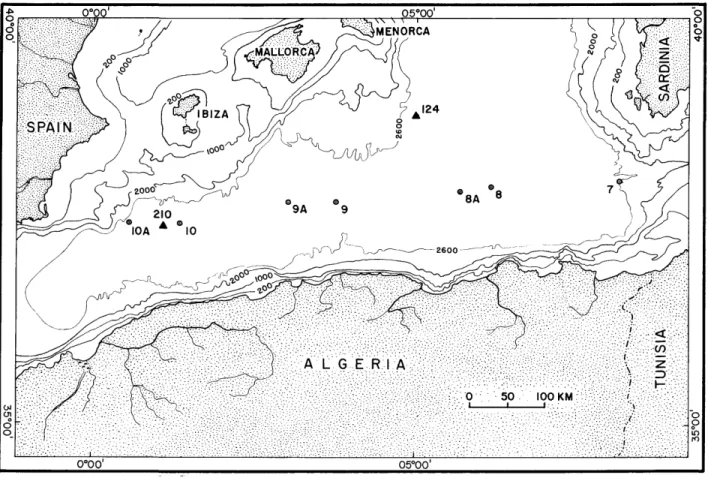
Geographic and Geologic Setting
The Balearic Sea, also referred to as the Algero- Provenc_al Basin, occupies most of the western Mediterranean. It extends from the Ligurian Sea in the northeast and the coast of southern France in the northwest, southward between Corsica- Sardinia and the Balearic Islands, down to the coast of North Africa. Cores examined in this study were collected in the southern part of the Balearic Sea, known as the Algero-Balearic Basin (Figure 1). The present geographic configuration has been explained in terms of rifting, lateral spreading, and rotation of microblocks (Iberia, the Balearic block, and the Corsica-Sardinia block)
(Ritsema, 1969; Hsu, 1971; Vogt, Higgs, and Johnson, 1971; Auzende, Bonnin, and Olivet, 1973;
Dewey, et al., 1973). In addition to lateral spread- ing, evidence for vertical tectonics has been pre- sented (Bourcart, 1959; Pannekoek, 1969; van Bemmelen, 1969).
The Balearic Basin is bounded by narrow shelves, platforms, and continental slopes that, for the most part, exceed 5°. These are in many places incised by submarine canyons (Bourcart, 1959).
They border a large, flat basin floor, called the Balearic Abyssal Plain, the largest basin plain in the Mediterranean Sea. The 2600 m bathymetric contour serves to delineate the abyssal plain (Carter et al., 1972).
The plain, a depositional feature, forms the surface of a stratified sedimentary fill, of which the thickness is estimated from subbottom profiles at 300 to 450 m (Horn, Ewing, and Ewing, 1972).
The total thickness of the Plio-Quaternary uncon- solidated sediment fill reaches to 1200 m in the vicinity of the Rhone Cone (Menard, Smith, and Pratt, 1965; Watson and Johnson, 1969; Ryan et al., 1969). Piston-coring surveys show that the sediment underlying the plain comprises mostly mud with some alternating graded and laminated sands and silts. JOIDES drilling in the Balearic Basin (Leg 13, sites 124, 133, 134) reveals thick deposits of Quaternary and Pliocene age, underlain by a Messinian evaporite sequence (Ryan, Hsu, et al., 1937a,b). For instance, at site 124 situated off the eastern margin of the Balearic rise (Figure 1), a thick sequence of rhythmically bedded sediments has been recovered. Its lower part (200 m), largely of Pliocene age, contains light- and dark-colored marl oozes and sand-silt laminae, which form the bases of the dark oozes. The upper part (160 m), of Quaternary age, contains alternating graded sand- silt layers and marl oozes. Nesteroff (1973) and Nesteroff, Wezel, and Pautot (1973) interpret the lowrer section as contourites, and the upper section as turbidites (cf. Nesteroff et al., 1972).
The abyssal plain surface has a slight gradient away from the main source of terrigenous sediment and toward its deepest part (2800 m) lying west of Sardinia. The most important terrigenous sedi- ment source is the river Rhone, the mouth and submarine fan of which are located in the north- western part of the basin (Menard, Smith, and Pratt, 1965; Horn, Ewing, and Ewing, 1972). The
SMITHSONIAN CONTRIBUTIONS TO THE EARTH SCIENCES
0 SO 100 KM
0°00' 05°00'
FIGURE 1.—Locations and numbers of seven cores taken from the Balearic Abyssal Plain (hiring March-April 1972 aboard the USNS Lynch. The isobaths are in meters. The 2600 in isobath delineates the abyssal plain. JOIDES leg 13 site 124 and core 210 of the Swedish Deep-Sea Expedition are also shown.
Rhone has been the main source of sediment since the Pliocene foundering of the northern Medi- terranean margin (Bourcart, 1959), and probably earlier. Another important source of fluvial sedi- ments is the North African margin (Leclaire, 1972a, 1972b; Vita-Finzi, 1972); much of these materials bypass the narrow shelf and move downslope, in some cases via canyons, toward the plain surface.
T o a lesser degree, sediments are also derived from the Iberian Peninsula, the Balearic Platform, and the Strait of Sicily. River input is to a large degree seasonally controlled; late fall to spring rains and snow-melt result in increased discharge during these periods (Semple, 1931). Seasonally shifting wind patterns also modify the volume of aeolian dust transported off the North African margin (Eriksson, 1965).
T h e movement of the upper two water masses [surface and intermediate or Levantine water (Wust, 1960; Lacombe and Tchernia, 1972)] are influential in the movement of fines and planktonic organisms in suspension. Little is known of bottom water flow and velocities (Miller 1972). Bottom photographs made in this region do not indicate evidence of significant bottom current activity. The role of large-scale vertical sinking of surface water in the northern Balearic Sea (Stommel, Voorhis, and Webb, 1971) as a significant mechanism in sediment transport to the basin plain has yet to be evaluated.
Earthquakes play an important role in trigger- ing turbidity currents, slumps, and other mass gravity failures along the steep, narrow margin of this region. The area is seismically active (Bara-
NUMBER 13
zangi and Dorman, 1969; McKenzie, 1970); a line of earthquake epicenters trends from the Azores to the Strait of Gibraltar eastward across North Africa to Sicily. The Orleansville earthquake of 1954, for instance, triggered a large turbidity current in the southwestern sector of the Algero-Balearic Basin, an occurrence well documented by cable breaks (Heezen and Ewing, 1955; Horn, Ewing, and Ewing, 1972).
The structural mobility of the region also affects sedimentation in other ways. Numerous salt dome diapirs (Watson and Johnson, 1969; Ryan et al., 1969) of Messinian age (Ryan et al., 1973) occur across much of the abyssal plain. Salt tectonics has disturbed the Quaternary sediment succession, in- cluding the uppermost Holocene strata in many places, particularly in the vicinity of 2° longitude (Stanley and Diester-Haas, 1973). Elongate salt knolls deflect sediment dispersal along the plain surface and locally act as dams against which strat- ified deposits are ponded (Figure 2).
Core Locations
During the March-April 1972 cruise of the USNS Lynch (LY-II-72), seven Ewing piston cores were retrieved from the Balearic Abyssal Plain at seven different stations in the Algero-Balearic Basin. The cores are coded from east to west LY-II-7, -8, -8A, -9, -9A, -10, -10A (Figure 1). Stations were selected for deepwater light scattering experiments, and not with a sedimentary basin analysis in mind. The cores, therefore, constitute random sediment samples from the Balearic Abyssal Plain.
TABLE 1.—Location, water depth, and length of sexien cores obtained from the Balearic Abyssal Plain on the USNS Lynch March-April 1972 cruise
(see Figure 1)
Core no.
7 8 8A 9 9A 10 10A
iMtitude
38°02.7'N 37°58.8'N 37°56.0'N 37°47.3'N 37°47.0'N 37°31.FN 37°32.0'N
Longitude
8°09.2'E 6°11.0'E 5°41.0'E 3°43.0'E 3°00.9'E 1°18.9'E O°33.5'E
Water (m) 2588 2719 2712 2674 2676 2655 2628
depth {fm) (1415) (1487) (1483) (1462) (1463) (1452) (1437)
Core length (cm) 342 428 382 513 444 445 461
The ship track, along which almost continuous 12 and 3.5 kHz echo-sounding records were ob- tained, extends from the western sector of the Strait of Sicily to the region south of the Balearic Islands and the southeastern coast of Spain in the vicinity of the Mar Menor. This east-west trending line constitutes an almost complete section across the Algero-Balearic Basin, and is oriented approxi- mately at right angles to the main directions of sediment supply (except for cores 7 and 10A).
Core location, length, and uncorrected water depth are listed in Table 1. Total core lengths range from 342 to 513 cm; the average core length is 431 cm. The water depth ranges from 2588 to 2719 m. The position of cores 8 to 10A, as indi- cated on echo-sounding records, is shown on Fig- ure 2.
Core LY-II-7 was collected on the lower fan sur- face of the Strait of Sicily Fan, just south of a levee bounding the southern margin of the Strait of Sicily Canyon.
Core LY-II-8 was retrieved on the almost hori- zontal basin plain surface, while LY-II-8A was cored in a wedge of stratified sediment ponded be- hind an emerged salt dome.
Cores LY-II-9, -9A, and -10 were collected in a zone of distinctly stratified sediment between salt domes south of the Balearic block; evidence of salt tectonism such as rim synclines, arching of strata, faults, and grabens occur in the immediate vicinity.
Core LY-II-10A was retrieved east of the Maz- zaron Escarpment and just beyond the Mar Menor Fan; the plain surface has a low gradient, and lies in a structurally active region in the westernmost Algero-Balearic Basin.
Lithologic Description of Cores
GENERAL
The seven cores consist predominantly of muddy sediments. Visual examination of split cores shows that much of the core sections appears homoge- neous (Figure 3). Lamont-Doherty cores taken in the same general area have been interpreted as consisting largely of homogeneous mud (Horn, Ewing, and Ewing 1972). In most of the cores, a few sand-silt and silt intercalations stand out as a result of textural and color differences (Figure 3).
The cores w7ere initially cut in 2 m sections and
s s
3 S
x P
s .
O Q
X S
NUMBER 13
t
8A-18 10-5 10A-19 9A-7
FIGURE 3—Photographs of split-core sections containing typical successions of turbidite sand-silt layers (8A-18, 10-5) or silt laminae or lamels (10A-19, 9A-7), and two types of mud layers, A(el) and B (ep). Note the absence of clearly visible layer boundaries within the muds. The interpretative column on the left is largely based on X-radiographs of these sections.. The first part of the section numbers refers to a core, the second to a rhythm within a core.
o
o
3
8-7 10-5 8-20 8A-11
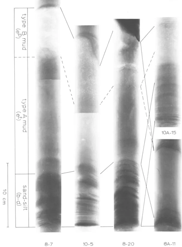
FIGURE 4.—X-radiograph prints and interpretative column of five rhythms of turbidite sand-silt layers or silt laminae, followed by largely homogeneous type A mud (e'), which in turn is followed by type B mud (ep) exhibiting light speckling. The lower part of type A layers can be finely laminated (10-5, 8-20, 10A-15). One rhythm (8A-11) contains no type B layer. In the turbidite sand-silt layer in rhythm 10-5, note current ripple lamination between two co-sets of lower and upper parallel lamination. Also note in type B mud layer two horizons of extra light speckled bands. The distinct horizontal lines in 8-7 and 10-5 are artifacts produced by the joining of two different photographic prints.
NUMBER 13
kept in cold storage, split, color logged, photo- graphed, and X-radiographed before sediment samples were taken for detailed analysis.
Figures 3 and 4, many of these lithologic bound- aries would go unnoticed without the aid of X-radiographs.
X-RADIOGRAPHIC IDENTIFICATION OF MUD LAYERS
The X-radiographs of split-core sections reveal that the sand-silt and silt layers exhibit several of the structural characteristics associated with tur- bidites. All layers are base-cutout successions of Bouma divisions, viz., Tu-c-d, Tc_d, or Td (Figure 4). The lowermost graded a-division is never pres- ent. The base of these layers is sharp, and fining- upward grading is macroscopically visible in the split cores. These layers are interpreted as typical turbidite sands or silts.
In addition to these turbidite sand-silt layers, the X-radiographs reveal a large number of distinct mud layers, many of which are very difficult to rec- ognize in the split cores (Figure 3). These more subtle layers overlie sand-silt turbidites, or they begin with a dark line on X-radiograph prints, constituting silt laminae (less than 1 cm thick) or lamels (less than 1 mm thick). T h e lower boundary of the coarser grained lower laminae or lamels is always sharper defined than the upper. Two kinds of mud occur above these layers, as well as on top of the turbidite sand-silt layers. Type A mud, which appears darker, lies directly on top of the coarser layer below. Its lower portion can exhibit delicate lamination. Type B mud appears lighter and is distinguished by light specks; it lies on top of type A mud and precedes the coarser layers (Figure 4).
The speckling is produced by interspersed micro- skeletons of foraminifera and pteropods in the mud.
The boundary between mud types A and B is often gradual and in some instances blurred by mottling and other evidence of bioturbation. The upper portion of type A mud layers can contain tubes consisting of FeS2 (Figure 18F). Such pyri- tized filaments are reported by Hesse and von Rad
(1973) in sediments from the Strait of Otranto.
These, readily apparent in X-radiographs, probably result from burrowing organisms.
Delicate and sometimes repeated scraping of the wet sediment surface of the split cores is necessary to observe the boundaries of the mud layers identified in X-radiographs. As can be seen from a comparison of core section 10-5 illustrated in
VARIATIONS WITHIN CORES
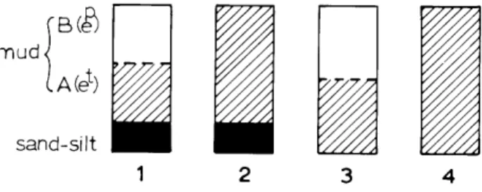
Vertical variation within the cores consists of a rhythmic succession of three members, viz., (1) the coarser grained turbidite sand-silt layer, or the silt lamina or lamel, (2) the type A mud layer, and (3) the type B mud layer. A unit consisting of any of the three members is herein called a rhythm. In some rhythms the lower coarser grained member is absent, or the upper type B mud member is missing, or both. In general, four types of rhythmic successions of the three members occur in the cores
(Figure 5).
sand-silt 1
FIGURE 5.—Four types of rhythmic successions of three member layers (sand-silt, and two types of mud) as found in seven cores from the Balearic Abyssal Plain (see Figure 6).
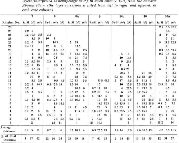
The average thickness of turbidite sand-silt layers is 4.5 cm; of type A mud layers 17.5 cm; and of type B mud layers 10.5 cm. The maximum thickness of type A mud is 47.5 cm, and the mini- mum thickness 1 cm. For type B mud, these values are respectively 53.5 cm and imperceptibly thin.
The measuring accuracy varies, but is approxi- mately 0.5 cm for the mud layers and can be 0.1 mm for the sand-silt layers.
VARIATIONS BETWEEN CORES
T h e sand-silt or silt members, type A muds, and type B muds are depicted in Figure 6; thickness data are listed in Table 2. The cores contain widely varying numbers of rhythms, viz., from cores LY-II-7 to 10A respectively: 25, 23, 22, 12, 18, 13, and 25. Their average thicknesses vary accordingly
(Table 2; Figure 6).
10 SMITHSONIAN CONTRIBUTIONS TO THE EARTH SCIENCES
TABLE 2.—Number, thicknesses (in cm), and thickness statistics of sand-silt turbi- dites (Sa-Si), type A mud layers (interpreted as turbiditic or ef, and type B mud layers (interpreted as hemipelagic or ep), in seven cores (7-10A) from the Balearic Abyssal Plain (the layer succession is listed from left to right, and upward, in each core column)
Rhythm No.
26 25 24 23 22 21 20 19 18 17 16 15 14 13 12 11 10 9 8 7 6 5 4 3
2
1 Average
thickness
% of total thickness
Sa-Si 0.2 0.2 0.2 0.4
0.3 0.2 0.2
0.2 0.2 0.5 0.3 0.2 0.2 0.1
0.2 1
7
5 10.5
8.5 6 11 3 4 4 5.5 8 5.5 3.5 10
8.5 5 4 3 1 4.5 3 2 2 2 5.5 2 5 37
(eP)
3.5 5 5.5 2 3 9.5 38 15 23 11 9 2.5 44.5 3.5 16
6 6 1.5 8
11 62
Sa-Si
3.5 16 12 10 13 2.5
1 4 8 0.3
3 8.5
10 2.5
6.7 22
8 (e*)
8 14.5
6 11.5 16.5 7.5 8 6.5 10
6.5 14
9.5 17.5 1 10 13 17.5
1.5 1 13 10 7.5 21
10 54
(e-)
2 8.5 6.5 5
1 3.5 3
4.5 14
7 3 8 14.5
5 3 2.5 11
6 24
Sa-Si
7
8 14 5.5 8
0.7 1.5 10.5 0.7 5.5 18
7 0.7
6.7 23
8A (el)
19 13.5
9 13.5 21 12 7.5 9.5 8 12 13 10 10.5 12 10.5 16.5 1 11 11.5
1 1.5 1 10.5 59
(ep)
2.5 3.5 7.5 3 3.5 3.5 9 7.5 3.5 6 5 6 1 4.5 2
4 18
Sa-Si
0.7 0.2 3
0.8 7 26 6.3 7
9 (e*)
11.5 16 17 45 41.5 17 18.5 22 45.5 13 47.5 10.5
25.5
60 (e»)
44.5
18 7.5 5 38 12.5
5 3.5 36
19 33
Sa-Si
4
0.5 2
2
0.4 0.3 0.5
1.4 2
9A (e*)
5 10 9 11 8.5 20.5 45 17 10 4 6 12 21.5 13.5 23 23.5
2 13
14 58
(ep>
16 14.5 25.5 1 23 3 8.5 6.5 17.5 27.5
2.5 2 5.5 4 1 2.5 12
4.5 3 9.5 40
Sa-Si
1.2 11
7.5 9 0.2
4 8.5 2.5 1.5 3
4.6 10
10 (e*)
21 12 11.5 13.5 23.5 35.5 28 24 18.5 10.5 15.5 14 15
18.5
55 (eP)
26 29 1 16 9 4 25.5 23.5 7 5.5 2.5 5 13 35
Sa-Si 2.5 2
5 0.3 0.5
6
33.5 1 2 0.8 0.3 0.4 1 55.2
4.7 12
10A (e»)
5.5 5.5 9 2 11.5
4 15.5
9.5 3 2 1 5 4 9 1.5 12
2.5 3 18 1.5 7
2.5 2 1 4
5.5 31
(ep) 42.5 0.5 11 12.5 53.5 6.5 3.5 2 5.5 4 3.5 7.5 6.5 16
1.5 3 3.5 7.5
1 23 4.5 31 14 11.5 57
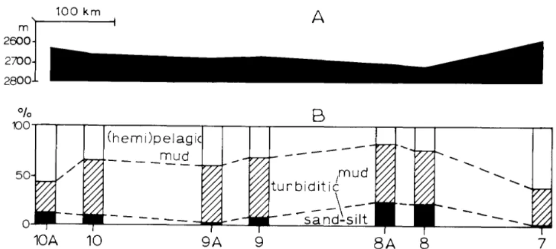
The ratios of the three different members change markedly from core to core, across the Algero- Balearic Basin. These changes correlate roughly with water depth. This is schematically represented in Figure 7, where the proportions of the different sediment types (B) are plotted along a bathymetric profile (A) from station 7 to station 10A. In cores at greater depth (8 to 10) the proportion of type A mud is more than 50 percent. In cores at shal- lower depths (7 and 10A) the percentage of type B mud is more than half (Table 2).
Another possible correlation is to be noted, viz., between lithology and access to fluvial sediment sources. Cores 8, 8A, 9, and 9A occupy positions
north of the important oueds on the margin of North Africa (Figure 1).
COLOR OF SEDIMENT
T h e sand-silt turbidites, when terrigenous in composition, are olive gray (5Y 4/1) in color. Bio- clastic layers are yellowish gray (5Y 7/2). Type A mud is light olive gray (5Y 5/2) to dusty yellow (5Y 6/4), whereas type B mud is somewhat lighter in color, namely, light olive gray (5Y 6/1) to yel- lowish gray (5Y 7/2). Color differences have been used to define mud layers (Bornhold and Pilkey, 1971; Davies, 1968; Fleischer, 1972; and others).
NUMBER 13
10 A 10 9 A 8A
11
2—
5—'
n Dating Sample lOpelagic Mud
M u d JTurbiditic Sand-Silt]
5,000 year Isochrons
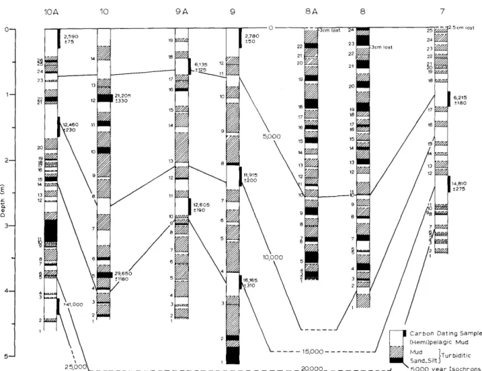
FIGURE 6.—Distribution of rhythms (numbered on left side of cores) consisting of turbidite sand-silt layers and two kinds of mud layers, type A (interpreted as turbiditic) and type B (interpreted as hemipelagic) in seven cores from the Balearic Abyssal Plain. Spacing between these cores corresponds to the distances between their respective locations. The position and extent of samples for radiocarbon dating and the corresponding ages are indicated. Isochrons are drawn between the cores, based on a calculation of the hemipelagic rate of sedimentation.
Note that in core 10 the radiocarbon dates are determined not on type B muds (interpreted as hemipelagic), but on resedimented turbidite sands, causing a dicrepancy between these dates and the ages indicated by the isochrons.
However, a comparison of color logs with X- radiography data shows that color is not a reliable boundary criterion. Color changes in the cores often do not coincide with layer boundaries, partic- ularly the boundaries between type A and type B layers. The boundary area can display mottling or can be uniform in color. A distinct color change is present within the type A mud member, some 15 cm below its boundary with type B mud in rhythm 18 of core 8A (Figure 3). Such discrepancies may be the result of burrowing activity.
Analysis of Rhythms
GENERAL
Eight individual rhythms were selected from six of the cores (7, 8, 8A, 9A, 10, 10A) for detailed sampling and analysis. The main purpose of the analysis was to establish and to contrast the prop- erties of mud types A and B in order to gain insight into their mode of origin. The rhythms are labeled by the number of the core and the number of the rhythm within that core. The following rhythms
12 SMITHSONIAN CONTRIBUTIONS TO THE EARTH SCIENCES
100
100 km
B
5 0 -
(hemi)pelagic mud
10 A 10 9A 7
FIGURE 7.-—A, An east-west schematic bathymetric profile across the Balearic Abyssal Plain from station 7 to 10A. B, Proportions of total turbidite sand-silt (black), total type A mud (hatched; interpreted as turbiditic), and total type B mud (white; interpreted as hemipelagic).
Note the rough correlation between water depth and proportion of turbidite sand-silt-mud.
were selected: 7-11, 8-7, 8A-11, 8A-18, 9A-7, 10-5, 10-12, and 10A-19.
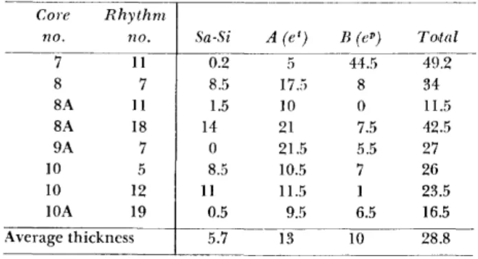
T h e rhythms were selected so as to represent variety in terms of spread between the cores, spread within the cores, thickness of the rhythms, thickness of the rhythm members, and type of rhythm. T h e thickness of the sampled rhythms ranges from 11.5 cm (8A-11) to 49 cm (7-11); the average thickness is 29 cm. T h e average thickness of type A mud layers is 13 cm and that of type B layers 10 cm (Table 3). All four types of rhythms (Figure 5) are represented. Two have a thick type A mud member (8A-18, 9A-7), and one has a thick type B mud member (7-11) (Table 3).
TABLE 3.—Thickness (in cm) of eight individual rhythms of sand-silt inrbidites, type A (eJ) and type B (ei}) muds, which were selected for detailed sampling and analysis
Core no.
7 8 8A 8A 9A 10 10 10A
Rhythm no.
11 7 11 18 7 5 12 19 Average thickness
Sa-Si 0.2 8.5 1.5 14
0 8.5 11
0.5 5.7
A(e') 5 17.5 10 21 21.5 10.5 11.5 9.5 13
B (ep) 44.5
8 0 7.5 5.5 7 1 6.5 10
Toial 49.2 34 11.5 42.5 27 26 23.5 16.5 28.8
A N A L Y T I C A L PROCEDURES
Samples were taken from the split-core halves.
The sample thickness ranges from 3 to 8 mm. The distance between samples varies from 0.5 to 8 cm.
A total of 59 samples has been analyzed. For the sttidy of clay mineralogy, four extra samples were selected.
The selection of exact sample points was based on the structural and textural details provided by the X-radiographs of the rhythms. The advantage of this sampling technique is that no subtle changes in sediment structure or texture were overlooked.
It also makes possible a more precise correlation between the sedimentary structures of the sediment sections and the results of the textural and compo- sitional analyses.
T h e following analytical procedures were car- ried out on all samples: (1) a grain-size determi- nation by pipette analysis; (2) a determination of carbonate percentage by gravimetric ascarite ab- sorption; (3) a compositional analysis of the sand fraction of all samples by grain-mount counting;
(4) a study of the overall composition, and in par- ticular of the clay mineralogy, by X-ray difrractom- etry and peak-height analysis.
T h e results are presented for each rhythm separately (Figures 8-15). Each figure is composed of five columns, the first of which provides the sedimentary structures (Bouma divisions) based on the X-radiographs. In this column the lower mem-
n 0>
3 cT
rain Size Distrib y?. Q
Carbonate Content
lomposition of Sand O
O CD r-t-
9> o o o
Q.
Co
7-11 Clay Mineral
Ratios
4 0 -
7-
6-
3 0 -
5 -
2 0 -
1 0 -
3-
0J 2 -
1 -
30 6 0 9 0°/oO 30 60°/o 0 3 0 6 0 9 0 %
\i
i
00
o 5
w o rr o"
1 \
w \
\
oo
CD cn
VCD
FIGURIS 8-15—Diagrammatic summaries of the sedimentary structures and textural and com- positional properties of eight rhythms from six cores from the Balearic Abyssal Plain. The coarse-grained material in the top part of rhythm 8A-11 may be due to burrowing from above rather than representing a separate type B mud layer. Sample numbers marked with "a" and
"b" were used only in the study of clay mineralogy.
14 SMITHSONIAN CONTRIBUTIONS TO THE EARTH SCIENCES
n co
3 0 -
2 0 -
10-
O -
omposition of Sand
TJ £
o o <* C G r a i n Size D i s t r i b
Clay M i n e r a l R a t i o s Carbonate
Content
Mica3-.-.-.piants
30 6 0 9 0%0 30 6 0 % 0 JO 60 90%
FIGURE 9.
ber of each rhythm (turbidite sand-silt layer or silt lamina) is indicated by Bouma divisions b, c, and d, while in anticipation of their genetic inter- pretation the middle (type A mud) and upper member (type B mud) are indicated by e1 and e"
respectively. In the three following columns, sample
points have been connected by straight lines, except where they lie on both sides of the mud A-B bound- ary. Where in X-radiographs this boundary is clearly denned, the lines are extrapolated from above and below and display the changes of texture and composition in the boundary region.
NUMBER 13 15
GRAIN-SIZE DISTRIBUTION
The grain-size distribution of the eight rhythms has been determined by pipette analysis. Measure- ments were taken at 1 phi intervals, between 4 phi and 9 phi (63 and 2 microns respectively). Type A mud contains less than 1 percent sand; thus, no size analysis of the coarser than 4 phi fraction was made. The terms "sand," "silt," and "clay" are used as grain-size terms without any compositional connotation.
The results are grouped and plotted in two different ways. (1) The percentages of sand (larger than 63 micron), silt, and clay (smaller than 2 micron) (Table 4) are plotted against sample point positions within rhythms (Figures 8-15).
These percentages also are plotted for all samples on a ternary sand-silt-clay diagram (Figure 16).
(2) The data are plotted as cumulative curves to show grain-size distribution on logarithmic prob- ability paper (Figure 17).
AD 1.—The coarse-grained, sand-silt turbidites in rhythms 8-7 (Figure 9), 8A-18 (Figure 11), 10-5 (Figure 13), and 10-12 (Figure 14) exhibit distinct fining-upward grading. The grading is reflected by an upward decrease of sand-size material and an increase in silt- and clay-size particles.
Eriksson (1965), in an extremely detailed exami- nation of core 210 of the Swedish Deep-Sea Expedi- tion, located approximately 20 km to the west of core 10 of this study (Figure 1), found two types of sand-silt turbidites. One type, with a high percentage of bioclastic material, is distinctly graded. The second type, with a high percentage of terrigenous material, has less developed grading.
However, this difference between the sand-silt tur-
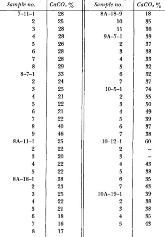
TABLE 4.—Percentages of sand-, silt-, and rhythms analyzed (samples are identified sample number, respectively)
clay-size material in samples from eight by core number, rhythm number, and
Sample no.
7-11-1 2 3 4 5 6 7 8 8-7-1 2 3 4 5 6 7 8 9 8A-11-1 2 3 4 5 8A-18-1 2 3 4 5 6 7 8
Sand 3 1 5 6 4 5 6
7 55 32 13
1 - - - 11 16 2 - - - 1 77 41 40 4 2 - - -
Silt 52 46 43 42 46 43 43 49 39 62 68 54 51 41 40 38 31 76 55 38 34 47 18 53 54 89 75 69 46 38
Clay 45 53 52 52 50 52 51 44
6 6 19 45 49 59 60 51 53 22 45 62 66 52
5 6 6 7 23 31 54 62
Sample no.
8A-18-9 10 11 9A-7-1 2 3 4 5 6
7
10-5-1 2 3 4 5 6 9 10-12-1
2 3 4 5 6 7 10A-19-1
2 3 4 5
Sand 1 12 13
- - 1 - - 6 9 71 35 26 3 - - 8 69 39 25
9 - - 9 1 - - 6 11
Silt 42 33 30 59 51 52 47 41 45 43 23 53 57 82 51 36 45 18 51 52 77 41 34 36 63 46 43 43 44
Clay 57 55 57 41 49 47 53 59 49 48
6 12 17 15 49 64 47 13 10 23 14 59 66 55 36 54 57 51 45
16 SMITHSONIAN CONTRIBUTIONS TO THE EARTH SCIENCES
Composition of Sand
Clay Mineral Ratios Grain Size Distrib
Carbonate Content
3 0 6 0 9 0%0 30 60°/.
CD CD CD FIGURE 10.
bidites of largely terrigenous rhythms (8-7 and 8A- 18) and largely bioclastic rhythms (10-5 and 10-12) is not observed.
Interestingly, the upper laminated division d shows a marked increase in the proportion of silt- size material. In the instance of rhythm 10-12, there is even a decrease in clay from the current ripple division c to division d.
Type A mud layers show a distinct fining-upward grading as well. The grading consists of an upward decrease of silt and an increase of clay. The shift in the silt-clay proportion can amount to as much as 20 percent. Most importantly, the grading of type A mud layers follows in regular fashion the grading of the underlying sand-silt turbidites or silt laminae. The sand-size fraction of type A mud is too low (less than 1 percent) to be plotted in the figures.
Type B mud layers exhibit no grading or, if any- thing, a slight coarsening-upward grading.
A distinct granulometric difference exists be- tween type A and type B mud layers. The former contain, little, if any, sand, maximally 0.62 percent, with an average of 0.2 percent. The latter, how- ever, contain a sizable amount of sand-grade mate- rial, maximally 16 percent, minimally 4 percent, with an average of 8 percent (Table 4; Figures
8-15). This sand is not graded as is that of the turbidite sand layers. In addition, type B mud lay- ers show a lower amount of clay and, in some instances, an increase in silt content, as compared to the underlying uppermost part of type A mud layers.
The granulometric change across the boundary between type A and type B mud members can be sharp. Where the change is not abrupt, the bound- ary area is mottled and can show other signs of bioturbation.
The absence of a systematic, fining-upward grading in type B mud layers is shown and under- scored by rhythm 7-11, in which type B mud is sampled over a thickness of 44.5 cm (Figure 8).
The grain-size characteristics of mud types A and B are difficult to compare with Eriksson's analysis of the fine-grained layers in core 210.
Eriksson divides the fine-grained layers in several groups, based on the type of material present and particularly on what he interprets as wind-borne components. However, in the diagrammatic repre- sentation of his results, several rhythms as found in our cores can be recognized. Grading in mud layers following on top of sand-silt turbidites or silt laminae occurs. Also, on top of graded mud layers, muds with a higher sand percentage are
NUMBER 13 17
OCD
4 0 -
3 0 -
2 0 -
10
0-
3
CD
z o
11-
10-
9b- 9a- 9-
7 —
6- 5-
4 -
n _
2-
1 -
d
c
omposition of Sand G r a i n Size D i s t r i b .
Carbonate Content
8A-18 Clay Mineral
Ratios
Ul 00
> o
7^
CO
o
.IU|
OJ U1
> o
olorite
00 Ul 00
> o
orr o
r-t-
A
fr\
>o 1 1
r-t-
CD —
1 /
00 Ul 00
CO
oini
r-t-
cp^
CD Ul
>o i—i
— r-t-
C D -
10 6 0 - 9 0o/<,0 60% 0 3 0 6 0 9 0 %
FIGURE 11.
18 SMITHSONIAN CONTRIBUTIONS TO THE EARTH SCIENCES
5CD Grain Size Distrib
2 0 -
10-
0J 4 -
3-
2-
1-
cn n
Carbonate Content
9A-7 Clay Mineral
Ratios
0 30 6 0 9 0%0 60% 0
omposition of Sand
CO CO CO
ijl Ol 01
i co oo oo
FIGURE 12.
indicated (cf., Eriksson, 1965, pi. 6, between depths of 484 and 443.5 cm in core 210).
The sand-silt-clay proportions of all 59 samples are plotted in a ternary diagram (Figure 16). A textural classification of the different rhythm mem- bers can be made, using the textural designations proposed by Folk (1961). The turbidite sand-silt layers, comprising the largest textural variety, in- clude silt, sandy silt, silty sand, and, in one instance, muddy sand. The type A mud layers classify strictly as mud. The type B mud layers can be mud or sandy mud.
The diagram also shows differences in sorting be- tween the three rhythm members. The turbidite sand-silt layers are the least sorted, whereas type A mud is the best sorted. Importantly, the diagram illustrates that the three rhythm members, defined primarily from X-radiographs, can also be recog- nized on the basis of textural analysis.
AD 2.—The cumulative grain-size curves (Figure 17) show even more distinctly the grading in the sand-silt turbidites. The lower, coarser grained part of the sand-silt layers exhibits coarse tail grading (the coarsest percentiles of the size distribution
NUMBER 13 19
10-
0J
" O CD
zo
5-
4-
3-
2-
1-
Grain Size Distrib
o
CD
Carbonate Content
Composition of Sand
<?
O CD_ CD O
10A-19 Clay Mineral
Ratios
FIGURE 13.
show the grading, particularly well displayed in rhythm 8A-18). Type A mud layers are distribu- tion graded (the entire size distribution shifts to finer sizes). Also shown clearly is that type B muds are not graded, neither internally, nor by a further size decline following that of the underlying type A mud.
Most importantly, the grain-size distribution within B type layers from various depths within the cores and from six cores at widely separated loca- tions exhibits very little variation and is uniform.
The uniformity within one B layer is particularly well shown for rhythm 7-11 (Figure 17). Type A mud layers, on the contrary, exhibit a much greater variability in grain-size distribution (Figure 17).
The average median diameter, as read off on the 50-percentile line, of type A muds (9.3 phi) is smaller than that of type B muds (9.1 phi), and it displays a larger spread (from 7.5 phi to 10.3 phi, as opposed to 8.4 phi to 9.5 phi).
The inclusive graphic standard deviation, or sorting, for type A mud is approximately 2, which is defined as poor to very poor (Folk and Ward
1957). The value for the sorting of type B mud is approximately 3, i.e., very poorly sorted. This dif- ference in sorting can be clearly seen from the differences in slope of the cumulative curves
(Figure 17).
The cumulative grain-size curves of type B mud tend to be straighter (almost perfectly so for some samples) than for type A muds. This means that the size distribution of the former approaches nor- malcy, more so than the latter.
CARBONATE CONTENT
The carbonate content of the eight rhythms was determined by gravimetric method, using the as- carite absorption technique. A small amount of sample (0.1 g) is treated with diluted HC1, and the liberated CO2 is directed through vessels con- taining agents that remove possible other vapors to the ascarite tube. The carbonate percentage can be calculated from the weight increase of the asca- rite tube. The accuracy of this method can be of the order of 1 percent. Results of the analyses are
20 SMITHSONIAN CONTRIBUTIONS TO THE EARTH SCIENCES
=;•(/> in -" n Co 3 CD ~D_
2 0 -
10-
0 -
7-
6a-
6-
5-
4-
3-
2-
1-
< ?
lam
b
Gram Size Distrib
Carbonate Content
Composition of Sand O
(D O
CO Co (Q
n' ~O CD
iMica
10-5 Clay Mineral
Ratios
ui CJI en
W 0 D C 0
> ° >o>o
n ^ T^
3 0 6 0 9 0%0 30 60% 0 3 0 6 0 9 0 %
FIGURE 14.
detailed in Table 5 and depicted in Figures 8-15.
The turbidite sand-silt layers have the highest average carbonate content (40 percent) and the widest spread of values (from 21 to 74 percent).
The overlying type A mud layers have the lowest average carbonate content (28 percent) and an intermediate spread (from 16 to 39 percent). T h e type B mud layers on top have an intermediate average carbonate content (35 percent) and the narrowest spread (from 26 to 46 percent).
In general, the carbonate content decreases with decreasing grain size. Within the sand-silt turbid- ites the carbonate percentage shows an upward
decrease. In some of the type A mud layers, for example those of rhythm 9A-7 and 10-12, the car- bonate content shows also an upward decrease by as much as 6 percent. As such, the A muds are not only texturally graded, but also compositionally.
This compositional grading follows that of the underlying sand-silt turbidites.
The continuity from sand-silt turbidites to type A mud layers above them is illustrated by the fact that where the former are low in carbonate content the latter are proportionally low as well (8-7, 8A-18), and the reverse (10-5, 10-12). T h e car- bonate content of the type B mud layers above
NUMBER 13 21
=;(/) Co
n E. 3
3 CD T3_
CD
2 0 -
10-
0J
o
i £
5-
4 -
3- 2-
1-
C a r b o n a t e Content G r a i n Size D i s t r i b
Composition of Sand 10-12
Clay Mineral Ratios
ui en en
U) 00 00
3 0 6 0 9 0 %
these does not change and is independent of that of the underlying rhythm members.
The carbonate content of the type B layers is relatively constant. An abrupt change occurs across the boundary, where the underlying type A muds have a low carbonate content.
The carbonate materials are almost entirely biogenic in origin (see following section). Based on the carbonate content as an indication of the amount of biogenic components, the sand-silt tur- bidites fall into two classes, terrigenous (8-7, 8A-18) and biogenic (10-5, 10-12). The type A muds can be clayey muds (8-7, 8A-11, 8A-15) or marl muds (10-5, 10-12, 10A-19). T h e type A muds of rhythm 7-11 and 9A-7 are somewhat inter- mediate between terrigenous and biogenic types.
Type B muds classify as marl oozes. Classification
as used here follows that of the Initial Reports of the Deep Sea Drilling Project (Ryan, Hsu, et al., 1973c), and is modified after Olausson (1960).
Although only a few rhythms have been exam- ined, it appears that the carbonate admixture of the sand-silt turbidites and the type A muds increases toward the west across the Balearic Abyssal Plain, i.e., from core 8 across the Balearic Abyssal Plain to core 10 and 10A.
COMPOSITION OF THE SAND FRACTION
T h e larger than 63-micron fraction was obtained for all samples by wet sieving. Grain mounts were prepared for identification of the constituents and for determination of their relative frequencies.
Relative frequencies were determined by counting