The basic idea is to perform a second maximum-likelihood decoding operation of the internal code that includes side information. The second chapter deals with a modification of the classical Viterbi algorithm for maximum likelihood decoding of convolutional codes, which allows some feedback from the outer algebraic code to the inner code. The basic structure of maximum likelihood decoding of convolutional codes comes from the state diagram of the shift register encoder.
As Figure 1 shows, the information to be encoded is entered into a shift register, and the output of the multiplexer goes to the radio frequency modulator. The number of outputs of the combinational logic (inputs to the multiplex~r) is 1/R, where R is the code rate. Viterbi decoding finds the most likely sequence of bits between the known start and end states of the encoder's shift register.
The bottom half of Figure 2 shows what happens to the trellis when one of the bits of information is known, and Table 1 shows the results. The power used by the symbols of the first outer codeword is now available to the symbols of the others. Looking at Table 1, we see that the percentage of errors for the remaining symbols has dropped to a very small value.
The redundancy of the code required to clean up these errors will be much less than one percent.
Convolutional Encoder
Trellis Diagrams
Alegraic Codes
CHAPTER IV Hardware Hardware
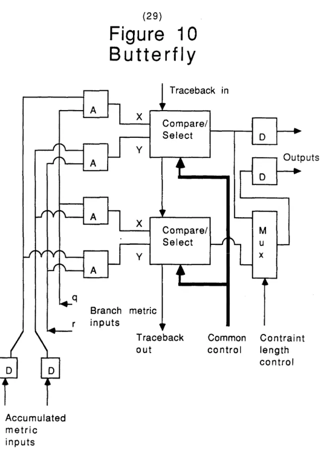
All "D" latches in all drawings with one exception in Figure 9 have a single clock in common. The inputs to the branch metric computer and all other arithmetic elements of the butterfly are shaped to ensure that the carry (or borrow) always clears. The outputs of the branch metric computer go to the butterfly body shown in Figure 10.
Here they are added to the accumulated metric input of the butterfly in all possible ways. These inputs and the outputs in the upper left corner of the figure are connected in a de Bruijn graph. A compare/select unit compares two numbers, X and Y, that it receives in bit array form and outputs the smaller of the two.
The word clock indicates the arrival of the most important bits and thus the time when the choice of the smaller of the two can be made. The length of these shift registers, N, is a very important parameter of the design both because the decoding speed is inversely proportional to N + 2 and because the area of the shift registers is a significant fraction of the total chip area required for the butterfly be required. . The dynamic range of the accumulated metric is limited to the product of the reciprocal of the rate, the counterline length mlnus one and the largest symbol size.
So if we could always locate the smallest metric and check whether its leading bit was a one, we would need N equal to one plus the largest integer of the base two logarithm of 10,668. Looking at just a single metric means that the spread can occur on either side of the renormalization threshold. If we look at two metrics whose symbol sets are antipodal, for example the all-zero state and the single-leading state, and always compare the larger of the two to the threshold, then the potential spread of the metrics around the threshold is only 1.5 instead of 2.
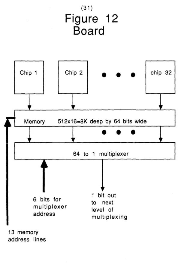
Always setting one of them to zero therefore has no influence on the operation of the decoder. However, during one of the two read cycles, only one bit is read from the entire traceback memory. The pattern repeats and each of the two active areas requires one of the two reads available in each master cycle.
Metric Computer
Compare/Select
Chip
Butterfly 16
Graphs
- Preliminaries About Strings
- DeBruijn Graphs and Subgraphs
- A General Construction for Universal DeBruijn Subgraphs
- Hierarchical Building Blocks
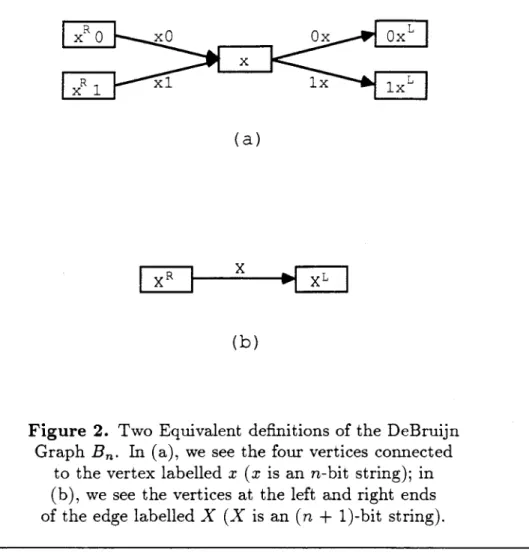
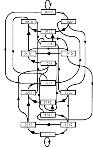
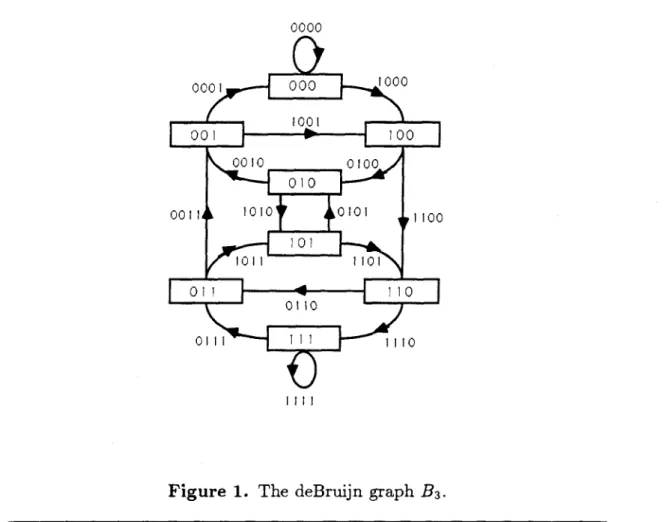
Peak tags represent the contents of the shift register at a particular point in time. The label at one end connecting one vertex to another represents the contents of the shift register preceded by the bit being inserted into the shift register as it changes from one state to another. In such a decoder, a "butterfly" (a pair of add-compare-select units) must be placed at each node of the graph, and all communication between the butterflies takes place along the edges of the graph.
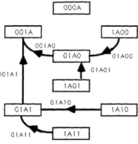
In this section we introduce some notation and establish a few elementary facts about binary strings that will be needed in the rest of the paper. Our goal is to build a large deBruijn graph EN by connecting multiple copies of a smaller graph, called a "building block." If we think of the building blocks as VLSI chips, it is natural to want to minimize the number of edges needed to connect the building blocks together. In other words, eff(H : G) represents the fraction of the edges of G that the edges in the building blocks represent.
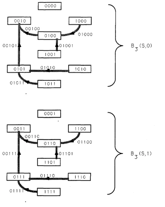
In Figure 4 we see two copies of the graph H in Figure 3, relabeled and connected with 20 new edges. Two copies of the B3 subgraph H from Figure 3, relabeled and connected to create B4 (edge labels omitted). A universal deBruijn building block of order n is an En subgraph that is a building block for every deBruijn graph BN with N ~ n.
In this section, we will present our main theorem (Theorem 4.3), which gives a general construction for the universal deBruijn building blocks. Proof of Theorem 4.6: Let the graph UIAl=N-n Bn(S, A) that appears in the statement of the theorem be called the union graph. Furthermore, this representation of the vertices' labels must actually be their S factorization, since an earlier occurrence of a substring from S in _xRsp or >.spL would imply an earlier occurrence of an S string in >.sp.
Proof of Theorem 4.3: Theorem 4.6 explicitly shows that the union of 2N-n copies of Bn(S) forms a subgraph (namely BN(S)) of the large deBruijn graph BN, so we can construct BN simply by adding the edges missing from BN to this union. It follows from the general theory of rational generator functions [4, Theorem 4.1.1] that omitn = 0(/3n), where /3 is the reciprocal of the smallest positive root of the equation 1-2z + z m = 0, which is also the largest positive one. The latter result is based on a more precise analysis of the type given in Theorem 5.6.).
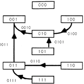
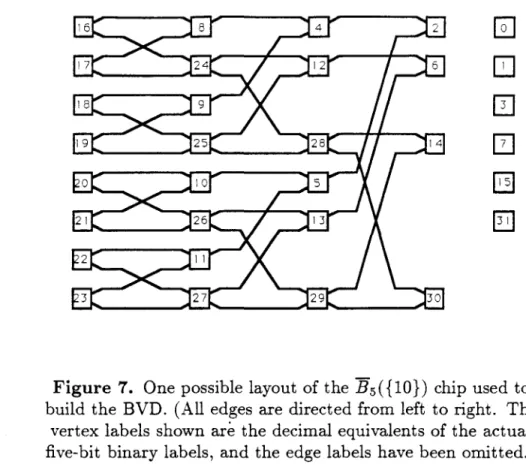
Given the connection between covers for { 0, 1} n and universal de-Bruij n building blocks, Corollary 5.7 implies the following. The . the node labels shown are the decimal equivalents of the actual five-bit binary labels and the edge labels are omitted.).
Bibliography