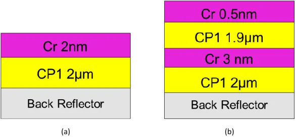
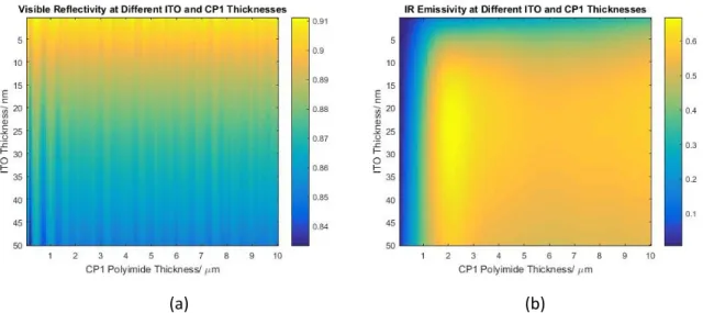
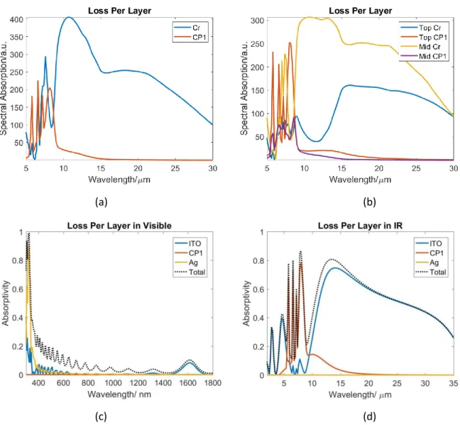
Refractive indices of (a) potential top conductors in the visible regime, (b) potential top conductors in the mIR regime, and (c) dielectric spacer layer CP1. (c) the reflectance of the visible spectrum and (d) the absorption capacity of the mIR spectrum of the two-layer Cr coating; (e) reflectance of visible spectrum and (f) absorptivity of mIR spectrum of specular ITO coating……….
Space-Based Solar Power
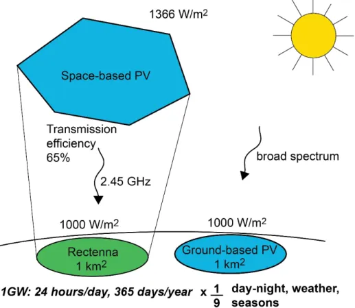
Principles of Space-Based Solar Power
Because it is always noon in space, the right orbit overcomes the intrinsic day-night limitation experienced by terrestrial solar cells. Inspired by the elegance with which this exciting, radical technology solves some of the intrinsic problems of solar energy, we dedicate this thesis to the development and study of photovoltaic technologies for SBSP.
Lightweight Solar Panels for SBSP
- Increasing Specific Power
- Concentrator Photovoltaics for SBSP
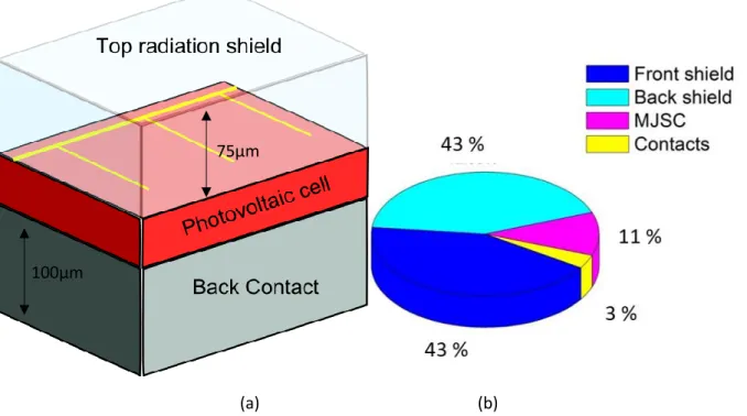
- Shield-less Flat Panel Photovoltaics for SBSP
In our body of work, this desire to reduce the amount of thick radiation shielding per unit area has manifested itself in two broad branches: concentrated solar photovoltaics and radiation-hard shieldless flat solar photovoltaics. By reducing the amount of space occupied by cells shielded from heavy radiation with lightweight solar concentrators, the high specific power required for SBSP can be easily achieved.
Thesis Outline
Generally speaking, the elimination of the radiation shield will result in a very high specific power. In fact, this specific capability has already been demonstrated in terrestrially flown flexible perovskite solar cells [25], making shieldless, radiation-resistant, flexible photovoltaic flat panels not only exciting for SBSP, but highly feasible.
Infrared Cooling Coating for Space-Based Solar Power
- The Need for Radiative Cooling in SBSP
- Heat Generation in Photovoltaic Devices
- Thermal Regulation Methods for Space-Based Photovoltaic Devices
- Emissive Coating Properties
- Design and Simulation of Thermal Coatings
- The Salisbury Screen
- Backside Coating Optimization
- Sun-facing Coating Optimization
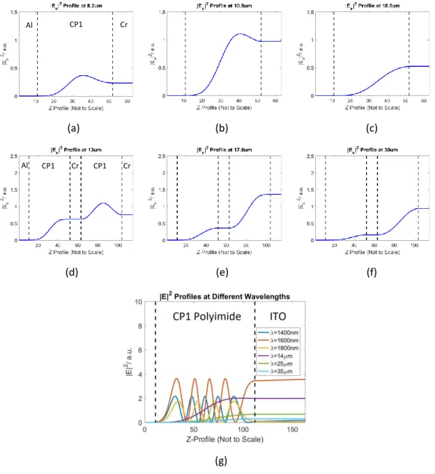
- Electric Field Profile
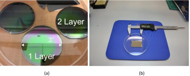
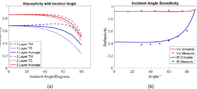
- Fabrication and Characterization
- Conclusion
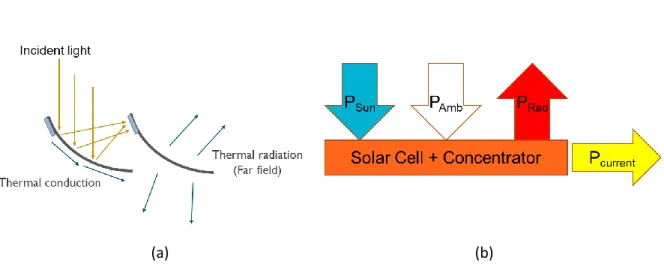
TRAd and TAmb are concentrator temperatures and space ambient vacuum. However, what has not been fully addressed is the nature of broadband light absorption.
Perovskite Fabrication Methods and Properties
- A Perovskite-Based Flat Panel Module for SSPP
- The Perovskite Cell
- Fabricating MAPbI 3 Devices
- Fabricating (FA1- x Cs x )PbI 3 Mixed Cation Devices
- Modelling the S-kink
- Conclusion
In the second, 16 mg of the surfactant cetrimonium bromide (CTAB-CH3(CH2)18NH3Br) was added to 400 mg of PCBM and 20 ml of CB in an attempt to improve electrical properties and wettability of the PCBM film [65]. In the same fume hood in the clean room, 50 µl of the NiOx precursor solution was spun on the slides at 3000 rpm for 60 s. Documentation of the FA-Cs manufacturing process (a) spincoated FACs films, (b) CTAB doped PCBM deposited (c) slides 1, 4 and 8 mounted on a SEM chuck and SEM photos of (d) slide 1, (e) .
Furthermore, the S-kink in the IV curve, absent from all the CTAB-doped PCBM recipes so far, makes a return in all the IV curves of the pure PCBM recipes, as seen in Figure X. This means that the rheology of the PCBM precursor is relevant to the manufacturing process and the final parameters of the device. Properties such as wettability and rheology, and their compatibility with the OHLP surface affect the ultimate quality of the top transport layer which affects the final device performance.
![Figure 3.2. JV curve demonstrating anneal recovery of OHLP cells damaged by protons [56]](https://thumb-ap.123doks.com/thumbv2/123dok/10401951.0/38.918.307.625.757.1011/figure-curve-demonstrating-anneal-recovery-ohlp-damaged-protons.webp)
Radiation Tolerance of Perovskites
Radiation Tolerance of Perovskites
The damage to the OHLP device appears to be most pronounced when protons are deposited into the OHLP layer itself. As such, when investigating low-energy, high-current proton radiation, we do not want to qualify an OHLP solar cell for SBSP, but rather investigate the nature of proton decay on OHLP cells by pushing them to further fluences. Furthermore, as we described in Chapter 3, an OHLP solar cell does not only comprise an OHLP film, but is a heterostructure containing at least 4-5 different material films.
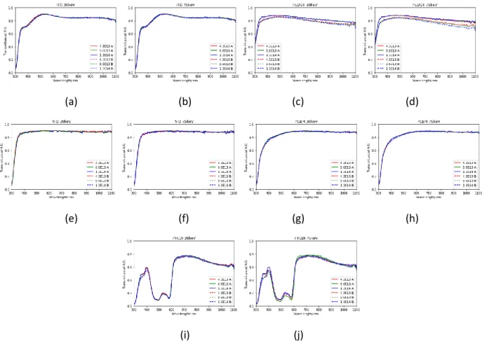
By observing the deterioration of key parameters such as resistivity and optical transmittance under increasing proton radiation influences, we can first assess whether they are suitable candidates for the unshielded space conditions we desire for our flat panel SBSP, and second we can take those parameters and calculate their theoretical effects on the solar cell. In particular, the ETLs and HTLs we chose are used in devices we will be actively testing, as well as other materials commonly used in OHLP devices. The HTL we will study is NiOx and the TCLs we will study are ITO and poly(3,4-ethylenedioxythiophene) (PEDOT).
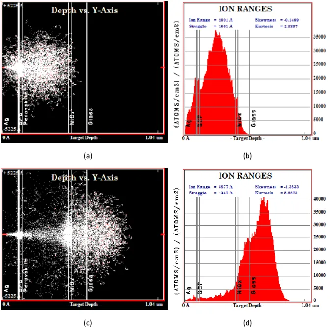
Stopping Range of Ions in Matter
Doing so will deepen our understanding of how an OHLP cell is damaged by protons, giving us a clearer picture of the full design space when designing OHLP cells for flat panel SBSP. To deepen our understanding of OHLP device degradation, it is important to characterize the degradation of the individual materials. Materials we want to focus on are the ETLs, HTLs and transparent conductive layers (TCLs) used at the top electrode.
Observing the differences between the 30 keV and 75 keV deposition profiles in Figures 4.1(a) and (c), we also noticed that in the case of the 30 keV irradiation, most of the irradiation is deposited in the PCBM - and OHLP layers, while in the 75 keV layers most of the irradiation is deposited. In that case, most of the protons are deposited in the ITO and glass layers. As for the rest of the single movie devices, from the plots in Appendix B, some protons will be deposited in the movies, so we should see some effect on it.
Thin Film Characterization
Covering only a strip of Ito the material means that there is an area of the chip that is just the material and glass, eliminating the ITO's effect on the measured transmission spectrum. These substrates had a strip of ITO across the middle, with exposed areas of glass, so that the glass background could be taken in isolation from the ITO and glass. We are looking for a way to quantify the effects of this observed degradation on the final performance of the solar cell.
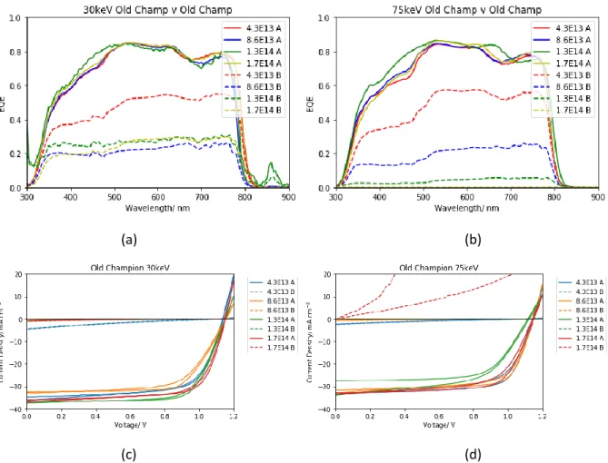
Note here that for each calculation we assume that the entirety of the series resistance comes from one single material. We know that the photocurrent is proportional to the spectrally integrated product of the photon flux and the external quantum efficiency (EQE). However, for most of the other materials we again note that the loss is less than 0.01.
Proton Irradiation of Perovskite Cells
56 degradation occurs due to the presence of protons that are deposited in the bulk of the OHLP absorber layer, which hinders the material's ability to generate a photocurrent. The hypothesis here is thus that the presence of protons largely catalyzes the kinetics of ion migration present in OHLP devices. Empirically a cell is subjected to much higher levels of illumination intensity in an IV light measurement than in an EQE measurement.
So far, we have developed a fairly solid understanding of the proton degradation of OHLP cells. This degradation occurs due to the presence of protons in the bulk, as opposed to protons passing through the film. We believe that the protons present in the bulk catalyze the intensity-dependent photodegradation of OHLP.
Anneal Recovery of Irradiated Perovskite Cells
However, we note that the temperature at which the gradient stops increasing varies from plot to plot. Specifically, in the case of cells damaged by 30 keV protons in Figure 4.13. a)-(d), the higher the fluence, the higher the temperature at which the maximum recovery occurs. Specifically, when observing the non-irradiated sample, we find that the Voc and FF of a normal, non-degraded OHLP sample decrease as the temperature rises.
When the recovery is complete, the cells show behavior similar to the unirradiated samples, with Voc and FF decreasing as the temperature increases from 70 °C to 90 °C. Clearly, there is additional damage to exposing a cell to 75 keV protons, which cannot be easily annealed. There we note that 75 keV protons are deposited at the OHLP/HTL interface in much larger amounts than 30 keV protons.

Radiation Testing of Flexible Perovskites
62 One can trace a possible cause of this damage by reviewing all the data we have so far. Trusting our conclusions from Sections 4.3 and 4.4 , we know that protons deposited in the HTL and TCL themselves should not be responsible for this severe degradation. Therefore, in the elimination process, it is clear that when protons are deposited near the OHLP/HTL interface, they cause dross to the device which cannot be easily annealed.
This is reinforced by the 30keV simulations which still show that trace protons are deposited near the OHLP/HTL. We note that just like the 75 keV samples, the 30 keV samples also showed some irreparable damage, and this irreparable damage increased with fluence, meaning that the more protons deposited at the OHLP/HTL interface, the ore irreparable damage happens. This means that no matter how much radiation shielding is used, and no matter how much annealing recovery is planned in the operating life cycle, the most important factor is to ensure that protons are not deposited at the OHLP/HTL interface.
Conclusion
64 degradation of PCE cells, with PEDOT being the most degraded material due to optical darkening of the film. However, this is only a fraction of the total cell damage that occurs with this type of radiation. First, annealing appears to remove protons deposited in the films, and more protons require more time and temperature to anneal.
Instead of determining radiation hardness and annealing recovery over a simulated ten-year life cycle, we instead identified degradation and recovery trends that allow us to better understand the design of OHLP cells for flat plate SBSPs.
Photovoltaic Technologies developed for Space-Based Solar Power
- Space-Based Solar Power
- Radiative Cooling of Space-Based Solar Power Structures
- Fabrication and Characterisation of Perovskite Solar Cells
- Proton Irradiation of Perovskite Solar Cells
- Outlook
Han, “Highly compact TiO2 layer for efficient hole blocking in perovskite solar cells,” Applied Physics Express, vol. Breakthroughs in NiOx-HTMs towards stable, cheap and efficient perovskite solar cells”, Nano Energy, vol. McGehee, “Barrier Design to Prevent Metal-Induced Degradation and Improve Thermal Stability in Perovskite Solar Cells,” ACS Energy Letters, vol.
Yang, “Dipole induced anomalous S-shaped IV curves in polymer solar cells,” Journal of Applied Physics, vol. Chen, “Recent Advances in Long-Term Stability of Perovskite Solar Cells,” Advance Science, vol. Zheng, “Atomic and Molecular Hydrogen Impurities in Hybrid Perovskite Solar Cells”, The Journal of Physical Chemistry C, vol.
Mohite, “Light-activated photocurrent degradation and self-healing in perovskite solar cells”, Nature communications, vol. Park, “The interplay between trap density and hysteresis in planar heterojunction perovskite solar cells”, Nano letters, vol.

![Figure 1.1. Spectral plots of the AM0, AM1.5 Direct, and AM1.5 Global solar intensity spectra [5] [7]](https://thumb-ap.123doks.com/thumbv2/123dok/10401951.0/13.918.188.732.719.1045/figure-spectral-plots-direct-global-solar-intensity-spectra.webp)
![Figure 3.4. Band alignment diagram of NiO x /MAPbI 3 /PCBM [64]. © 2018 He, Zhang, Zhao, Lin and Ye](https://thumb-ap.123doks.com/thumbv2/123dok/10401951.0/40.918.144.781.788.1006/figure-band-alignment-diagram-mapbi-pcbm-zhang-zhao.webp)
