The infrastructure design final report is one of the requirements for obtaining a bachelor's degree for the Civil Engineering course at Atma Jaya University, Yogyakarta. Nectaria Putri Pramesti, S.T., M.T., as our three teachers on Final Project Infrastructure 2 who guide us in arranging project management. Therefore, we expect constructive criticism and suggestions for the perfection of this article and this final project.
The author hopes that this Infrastructure Design Final Project report can be useful for all readers, especially for civil engineering students at Atma Jaya University, Yogyakarta.

INTRODUCTION
- Background
- Top Structure Planning
- Bottom Structure Planning
- Cost and Time Planning
- Statement of the problem
- Top Structure Planning
- Bottom Structure
- Cost and Time Planning
- Scope of The Problem
- Top structure planning
- Bottom Structure Planning
- Cost and Time Planning
- Objective
- Top Structure Planning
- Bottom Structure Planning
- Cost and Time Planning
- Methodology of Research
- Top Structure Planning
- Bottom Structure Planning
- Cost and Time Planning
- Outline of Final Project Report
This plan contains the design and calculations we made based on a review of the processed data analysis of soil bearing capacity, soil type and overburden. The design of the building structure to obtain the dimensions of the structural elements in terms of strength and stability against force action. Know the calculation of the volume of work and the budget plan at the Assalaffiyah Islamic boarding school project in Yogyakarta.
The major part of the preparation of this final project is in the second part, which consists of five chapters.
UPPER STRUCTURE PLANNING
Preliminary Design
- Planning Regulations and Standards
- Structural Material Specification
Interpretation of Soil Data and Site Class Purchases
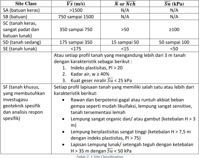
- Define Site Classification (SA-SF)
- Determine the site coefficients (Fa and Fv)
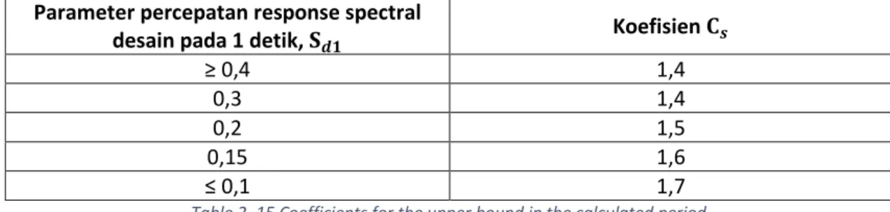
- Calculating design acceleration parameters (SDS dan SD1)
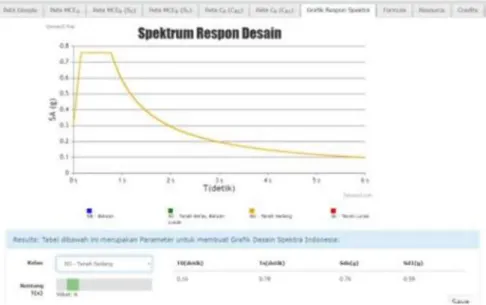
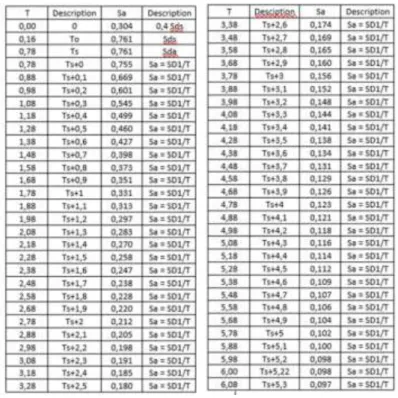
- Constructing the design spectrum response curve
- Define seismic design category (KDS: A - F)
- Define system and structure parameters (R, Cd, Ωo)
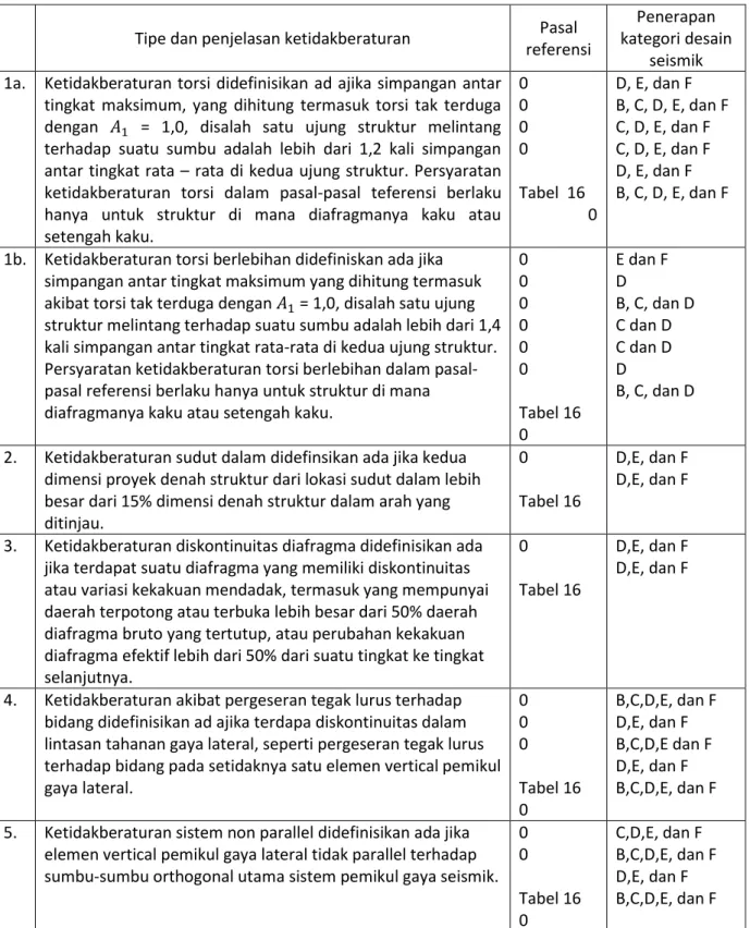
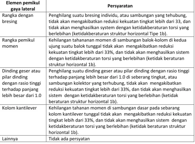
- Evaluating structural systems for structural irregularities
- Determining the flexibility of the diaphragm
- Determine the redundancy factor (ρ)
- Selecting the lateral force/earthquake analysis procedure (ELF, RS, TH) 23
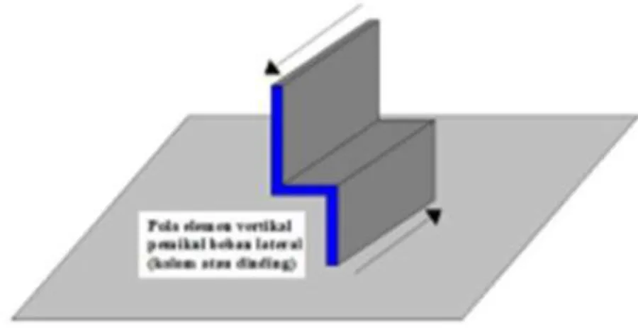
Based on the inspection of the irregularity of the discontinuity of the plane direction in the irregularity of the vertical lateral force-resisting member, it was found that there was no type 4 vertical irregularity in the investigated structure. A story lateral strength irregularity discontinuity is defined to exist if the story lateral strength is less than 80% of the story above it. A discontinuity in the excessive irregularity of the lateral strength of the story, defined to exist if the lateral strength of the story is less than 65% of the story above it.
Based on checking the irregularity of the discontinuities in the excessive lateral strength irregularities, it was found that there was no type 5b vertical irregularity in the structure under review.
Structural System Determination
- Structural System
- Structural Model
- Use Limit Performance
- Ultimate Limit Performance
SDS = Design spectral acceleration parameter for a short period of 0.2 seconds. The final load combinations used in this work are shown in Table 2.16. One of the service limit parameters that will be evaluated is the inter-story deviation due to the influence of the design earthquake for each of the orthogonal axes of the structure. In the ultimate performance limit, the ultimate load combination is used to analyze the internal forces acting in the structural elements.
The ultimate limit performance will determine the safety of the structure in supporting the ultimate design load acting on the structure.
Structure Loading Planning
- Gravity Load
- Earthquake Load
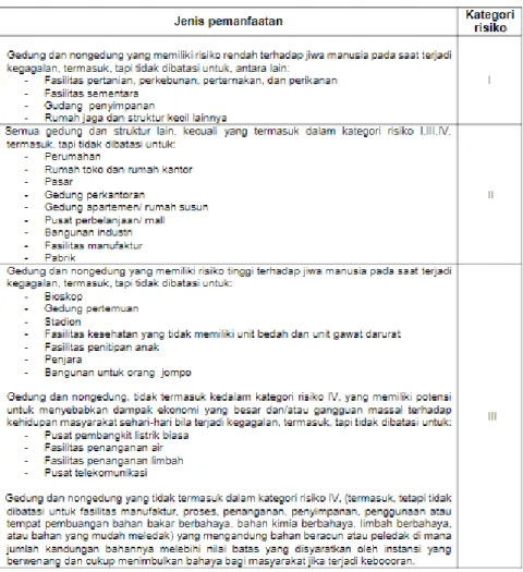
Additional dead load is an additional load resulting from the use of non-structural components (architectural and MEP) that are attached to and load the main structure of the building. Live load is the load that occurs as a result of the use of the building structure. In this work, the structure of the Islamic boarding school Assalafiyyah is included in the category of public buildings, so that it is classified as construction risk category IV.
In this work, the location of the building is in Yogyakarta city, so the values of Ss = 1.
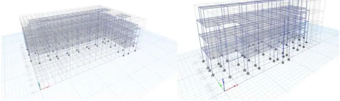
Structure Modeling
- Structural System
- Structural Model
The plate's moment of inertia is reduced to 25% of the initial moment of inertia. In beam structural elements, the moment of inertia is reduced to 35% of the initial moment of inertia. Whereas the moment of inertia in the column is reduced to 70% of the initial moment of inertia.
The structure of the restaurant is designed using a structural system in the form of a special moment-resistant frame structure.
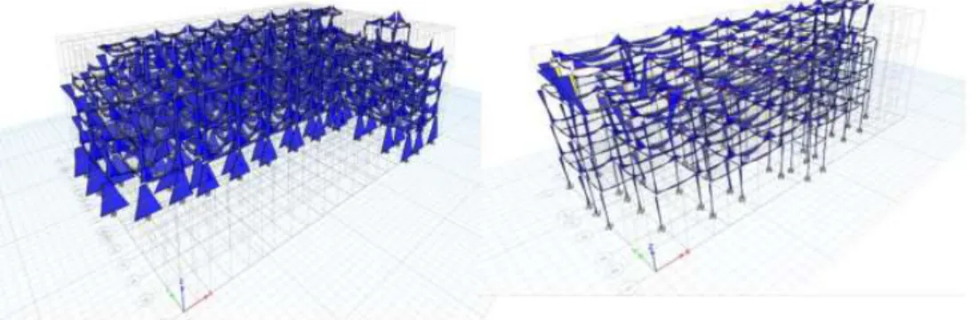
Interpretation of Modeling Output
- Inner Style Results
- Structure Behavior Check
- Inter-Story Deviation
The load combination used refers to the 2012 Earthquake SNI, in this report the discussion of the load combination is carried out in the Data Input - Load Combination section. In the variance response spectrum (RS) seismic load analysis procedure, the obtained base displacement must be compared to the base displacement resulting from the equivalent lateral force (ELF) seismic load analysis procedure. The base shift of the variance response spectrum (RS) shall not be less than 85% of the equivalent lateral force (ELF) base shift.
In the following, the results of the calculation and checking of the base shift to determine whether it is necessary to recalculate the power scale factor for the variance response spectrum (RS) are presented.
Roof Structure Design
- Dormitory Roof
- Dormitory Second Roof
- Educational Roof
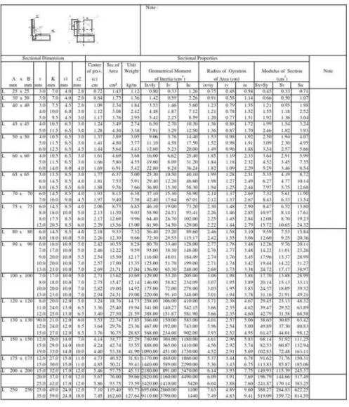
- Truss Element Design Planning
- Truss Connection Design
Compressed structural components are connected by means of bolts, so it is necessary to know the a/r value using the formula (2.9) with the result 139.846 where a/r > 40 thus. Thus, the design compressive strength value can be calculated using formula (2.13) with the result 25087.7 kN. The nominal tensile strength due to yielding in tension is obtained through formula (2.15) with the result 331680 kN.
Compressed structural components are connected using bolts, so it is necessary to know the a/r value using formula (2.10). Thus, the value of the design compressive strength can be calculated using the formula (2.13) with the result being 10756.3 kN. Compressed structural components are connected using bolts, so it is necessary to know the a/r value using the formula (2.9) with result 149.533 where a/r > 40 is therefore used.
The design compressive strength value can therefore be calculated using the formula (2.13) with the result being 22039.6 kN. It is known that the tensile yield that occurs at the gross cross-section is greater than the strength of the roof tension rod, so it can be concluded that this is safe. It is known that the net cross-sectional tensile failure is greater than that of the roof tension rod, so it can be concluded that this is safe.
The tensile strength is calculated by formula 2.17 with a result of 324 kN, which is greater than the strength of the tension rods on the outside and inside of the roof, so it is safe. The number of screws is calculated using formula 2.23 with the result 3.1281 rounded up to 3 screws.
Beam Design
- Beam Calculation (Ex. Main Beam 1)
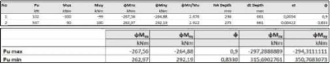
Column Design
The requirement for transverse reinforcement must be spaced in all directions along which lo does not exceed the smallest value of. The spacing of transverse reinforcement in the area outside l0 is given stirrups with spacing s not exceeding 6db and 150 mm. The shear strength requirements of the SRPMK column must have a design shear force (Ve) determined by considering the maximum forces that can occur at the face of the beam-column connection in each structural member.
Then the transverse reinforcement along lo must be designed to resist shear assuming Vc = 0 this can happen if the earthquake shear force is at least 50% of the required shear strength is maximum along l0 and the factored axial compressive force Pu including the earthquake effect is less than Agf' c/20. The shear strength of the SRPMK column design can be calculated using the equation below.
Floor Slab Design
- One Way Slab
- Two Way Slab
With two-sided slab reinforcement, the load received is distributed by the slab in two directions, with all four sides being supported. If the plate rests on all four sides and the ratio Ly/Lx < 2, the entire load is transferred to all sides. 2 Approaches for performing system analyzes and designing a two-way structure in accordance with, among others, SNI2847:2019. Direct Design Method, DMM This method is formulated in SNI 2847:2019 article 8.10, where this method is limited to floor systems loaded by uniform loads.
Using an efficiency number to determine the magnitude of the design moment at a critical location. The lengths of the adjacent spans, measured between the axles and the axes of the supports in each direction, do not change and are more than one third of the longest span (8.10.2.2). The rectangular plate with the ratio between the long span and the short span is measured from the axis to the supporting axis and does not exceed d.
The calculated load is only the gravity load and is uniformly distributed over the slab (8.10.2.5).
Stairs Planning
- Dormitory and Educational Building Stairs Design
Conclusion
In the design of directional slabs, Assallafiyyah Islamic Boarding School has 6 types of bidirectionally reinforced slabs and 16 types of unidirectionally reinforced slabs. The stair design in building one has a D16-300 main rebar, a D16-150 field main rebar and a P10-200 shrink bar. In the second building, the stair design has D10-300 main support reinforcement, D10-100 main field reinforcement and P8-150 shrinkage reinforcement.
BOTTOM STRUCTURE PLANNING
Interpretation of Soil Data
- Site Classification
- Category design Seismic
- Soil Data Interpretation
- Planning Regulations Standards
- Given Soil Data
- Bearing Capacity Analysis
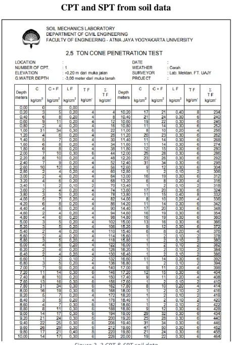
When evaluating the test results, the possible influence of the equipment on the geotechnical parameters must be taken into account. From the soil data provided in the form of drilling test results (CPT) and Standard Penetration Test (SPT) by TAPI II lecturers on soil bearing capacity, soil data number 7 is obtained, and adjusted to the soil site classification provided, the processing results are obtained in use by the SPT -method because the test process by the CPT method produces an unsatisfactory value (the results of the calculation of the soil bearing capacity do not show an increase from a depth of 3 meters to 20 meters). In geotechnical engineering, bearing capacity is the capacity of soil to support the loads applied to the soil.
The bearing capacity of the soil is the maximum average contact pressure between the foundation and the soil that should not cause shear failure in the soil. The calculation method will be used as a benchmark to determine the minimum depth as an initial benchmark for the piles to be used in the calculation of the piles and to determine the bearing capacity of the soil to support the building. Skempton (1986) proposes an equation to correct for N from the field, taking into account the influence of test procedure, borehole diameter and length of drill rod.
To perform the SPT test, the SPT data provided previously contains the type of soil at a depth of 1 - 25 meters, the N value and a graph of the SPT value. From the soil the interpretation table it is determined that the soil is loose soil type. Comparison of the Soil Bearing Capacity value after separation of the safety factor from empirical and analytical methods (Terzaghi and Vesic).
But the results of soil bearing capacity calculations at a depth of 17 m and 19 m which are slightly above and below a depth of 18 m show safe results. So as an initial reference we use as the depth of the deep foundation remains at a depth of 18 m as an initial guess.
Foundation
- Calculation of Deep Foundation
- Pile Group
- Pile Cap Reinforcement
Settlement
- Consolidation in the Dormitory
- Consolidation in the Educational
COST AND TIME PLANNING
WBS Preparation
Calculation of the Volume Activity
- Volume Activity of Preparation Work
- Volume Activity of Bottom Structure work
- Volume Activity of Upper structure Work
- Volume Activity of Architectural Work
- Mechanical. Electrical and Plumbing Work
- Plumbing. Drainage. and Additional
Unit Price Analysis
- Preparation work
- Bottom Structure Work
- Upper Structure Work
- Archictectural Work
- Mechanical. Electrical and Plumbing Work
Activity Duration Calculation
Determining The Relationship Between Activities and The Type of Overlap
Preparation of Network Diagrams
Preparation of Barcharts and S-curves
- Barchart
- S-Curve
Resource Scheduling
Conclusion
CONCLUSION AND SUGGESTION
Conclusion
Suggestions
Beam Reinforcement Recap
Work Volume Calculation
Unit Price Analysis
Duration Calculation
Bill of Quantity
Microsoft Project
Gantt Chart
S-Curve
Network Diagram