Specifically, his recognition of the importance of this type of problem and his unique suggestions about the approach made it possible to carry out the present work. However, near the tip, where singularities of the linearized theory occur, a non-linear local solution is used. CD drag coefficient based on the cord length normalized by the dynamic pressure on the cavity in the direction of the.
Several methods exist for attacking free fairing problems of the type associated with hydrofoils. In what follows we describe the basic idea of the new application of this theory to the present problem. This is the region of the flow that in the parlance of the singular perturbation literature is called the "inner region".
In the former, the pressure gradient across the body becomes infinite in the wetted body at the point of detachment and the resulting freestream curvature is infinite at this point. In this process, the shortcomings of the linearized theory are eliminated by eliminating its singularities.
PART I
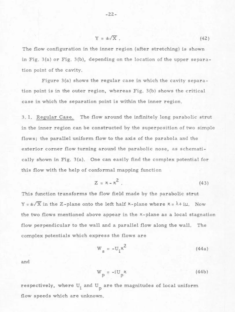
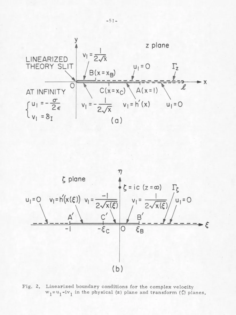
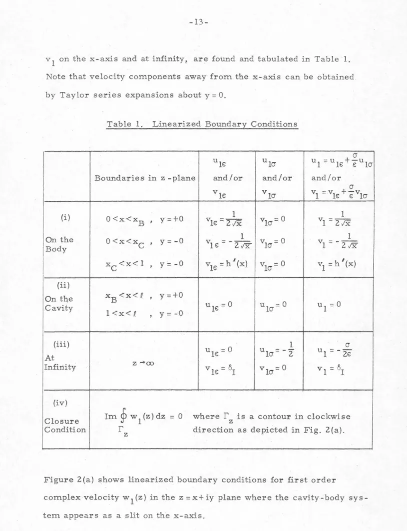
The boundary conditions in the present task, which should be met by the complex velocity potential w(z) = u-iv are:. i) the flow is tangent to the body, so that on the wetted part of the hydrofoil. Due to the appearance of the free streamline in the inner region, there is no easy way to find the exact inner solution as for the ordinary case. The final results are then found to be accurate for the desired order. is the size of the local. uniform flow rate in Z plane.
In this case, the outer solution is expanded with respect to x whose order is 11 e:2 " (the inner range) and also the inner solution with respect to x whose order is 11111 (the outer range). The superscripts are used for the upper part body, and the lower characters for the lower part of the body. It should be noted that the matches of the present problem were performed around the nose.
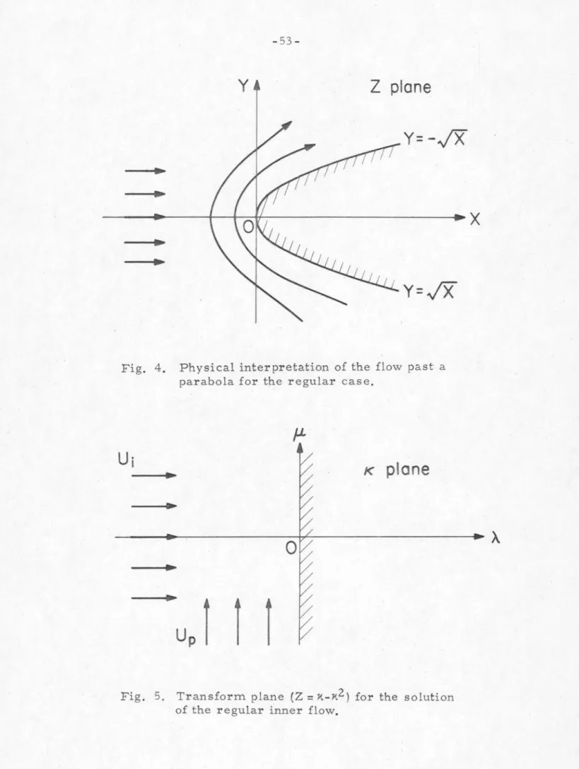
Physical interpretation of the flow past a parabola for the usual case. x. 2 ) for solving the regular inflow. Variation of the pressure coefficients as a function of the angle of attack on the parabolic strut of Fig. Variation of the pressure coefficients as a function of cavity length on the parabolic strut of Fig.
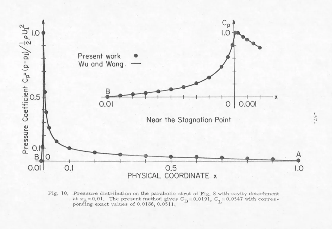
The variation of the pressure coefficients as a function of the cavity disconnection point in the parabolic column of Fig.
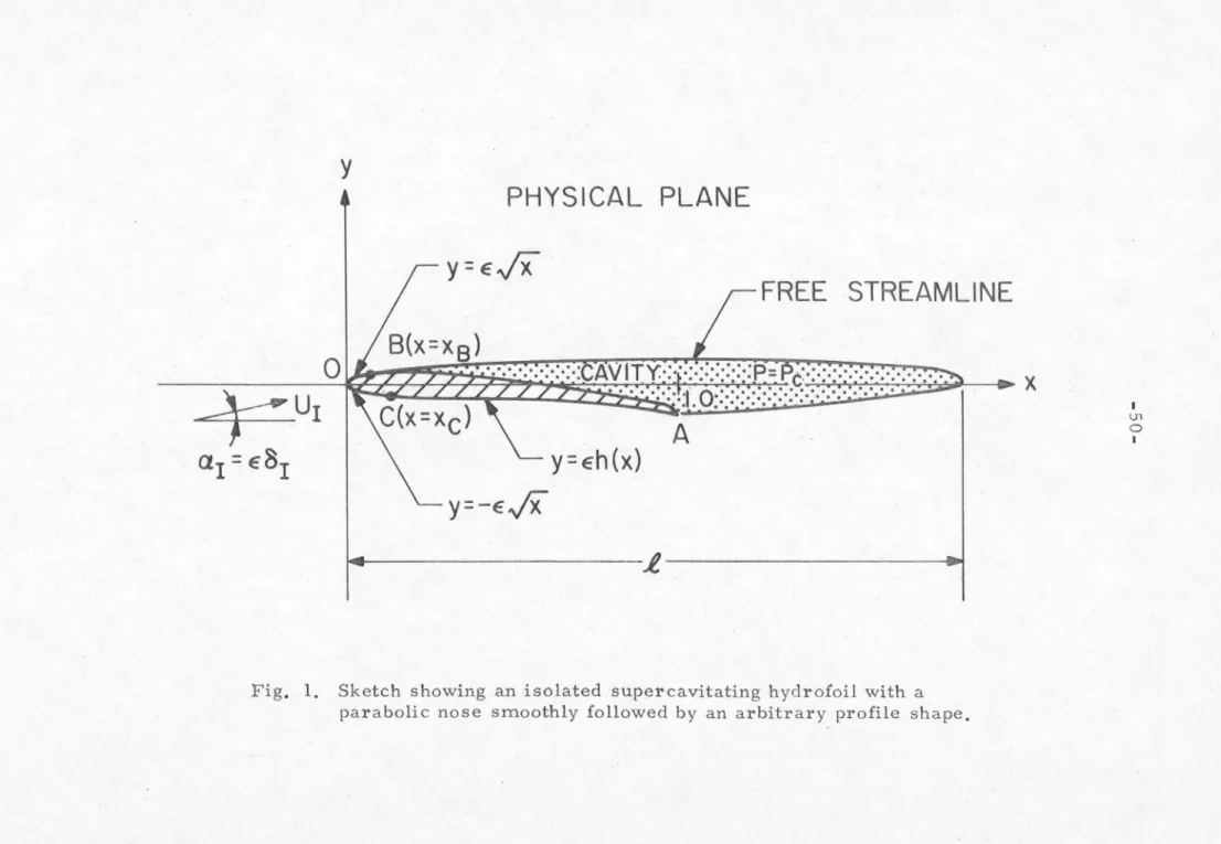
FREE STREAMLINE
AT INF INITY
Z plane
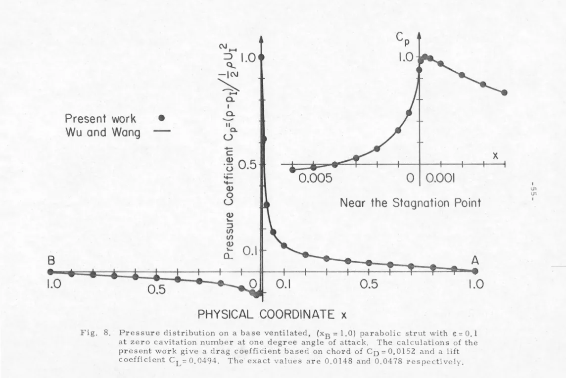
Present work
Wu and Wang •
Near the Stagnation Point
PHYSICAL COORDINATE x
Present work Wu and Wang
NEW CALCULATIONS WITH Wu AND Wang s I
PRESENT WORK
John son 8 Starley [14J)
CAVITATION NUMBER er
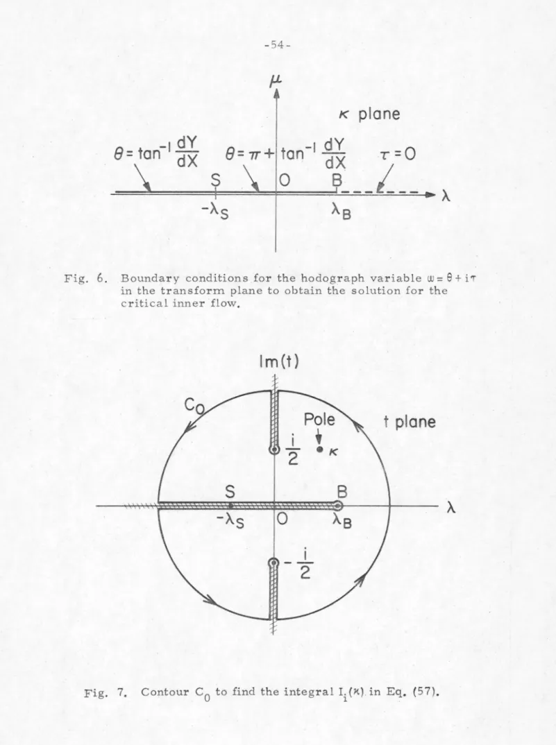
2s + · · · where Ei are constant But as S -+O, we note that this second term reduces to the first term so that we can identify E. The term I;(s,O) is now proved to be i regular as S -+O so that the expansion made in Eq. In general, iterative functional methods for nonlinear equations are very unstable if the solutions have singular behavior.
The combination of the present problem with Wu and Wang's functional iterative method exactly corresponds to this situation as mentioned above. This oscillating result in the iterations was obtained by applying the method proposed in Wu and Wang's paper to the present problem. We also have Lurye's report (Ref. 15) where this method was applied to the same problem (base-vented parabolic struts) and did not get the convergent solutions.
But it seems too hasty to abandon Wu and Wang's method because of its straightforwardness and usefulness. In what follows, we describe its most important items, leaving the details of numerical techniques to Wu and Wang. For any functional iterative method, we need a first-guess function to start the iterations with.
The base flow taken here was that of an inclined flat plate with an infinite downward cavity for two reasons; first, the solution can be obtained analytically so that it can be used for the next iteration, second, its stagnation current presents a problem to be solved, so the stagnation point is easily controlled by changing the incidence angle cx.B as1c . The quantities returned to the next iteration are given, for example, by . In particular, in the region of steep function change, the spatial increments for numerical integrations must be small enough to reduce large errors there.
The single precision was found to be not accurate enough to express the rapid change in the singular region. After considerable trial and error in the computer programs and meeting all the requirements as stated above, the same divergent problem as shown in Fig. Another example of convergence in which the flow configuration is exactly the same except that the thickness is half and the cutoff point xB = 0.05 is shown in Fig.
THE BAS IC FLOW TO START
1 or the velocity on the cavity Uc· A schematic sketch of the cascade flow configuration used by these authors is shown in Fig. The angle between the y-axis perpendicular to the x-axis and the line passing through the leading edges of the hydrofoils is called the offset angle, Y. The body-cavity gap is assumed to be defined by the line joining the nose of the leading edge and the end point of the cavity.
Therefore, the errors in the lift and drag forces due to the first order offset of the body cavity system from the x-axis. It is determined in such a way that for a given cavity length and offset angle Y, the end of the cavity lies on the x-axis. The boundary conditions in the current problem remain the same as those of Part I (see Chapter 2 of Part I) except for the new condition added for the location of the cavity point. iv).
1 (CJ on the real axis s, which is approached from the upper and lower sides of the axis, respectively. The velocity distribution on the wetted part of the hydrofoils in the first order is then given by z. The leading terms in the required expansion of the external matching solution are found to be.
In the critical case, only the speed in the lower part of the body remained, since the match happens there differently than it. The main terms in the expansions of the interior solutions for x= 0(1) are for the regular case,. Therefore, the diameter of the leading edge is found to be 0.005, and the upper point of the cavity separation is fixed at sa:me as this diameter, i.e.
The angle and/or camber of the body can then be increased by smoothly separating the cavity before the new fixed separation point, so that greater lift can be obtained. We need to show here how to find the upstream current angle and also the angle of the vector mean with respect to the chord line. Variation of the pressure distribution with different offset angles y on the same hydrofoils as Fig.
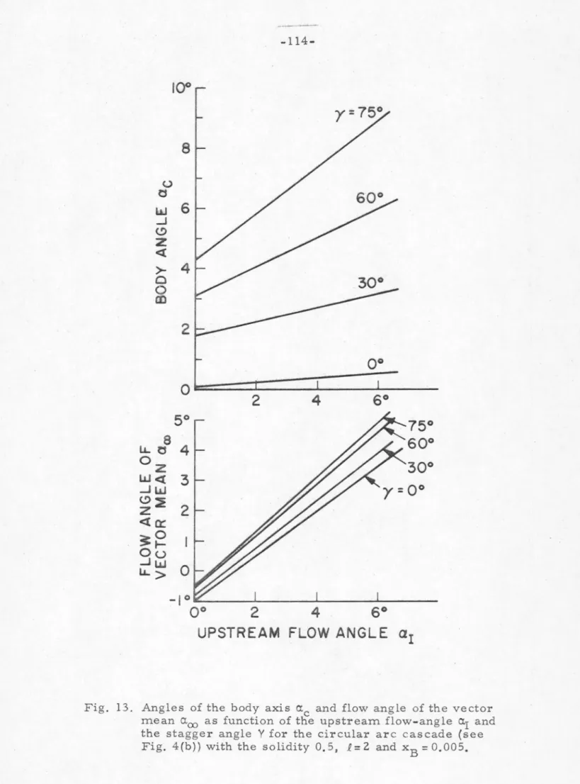
00 as a function of the upstream flow angle a.1 and the offset angle y for the straight line cascade (Fig. 00 as a function of the upstream flow angle °I and the offset angle Y for the circular arc cascade (see Fig.

DETAILS OF HYDROFOILS
J2xcx(!}-x 2 Ce)
NOSE
ROUND NOSE DIAMETER 0.005
Pressure distributions on the flat plate hydrographs of linear cascades with elliptical noses with the offset angle Y = 30°, the solidity 1.0, the cavity separation point xB = 0.005, the cavity length£= 2.0 at different angles of attack.

NOSE
L= 1-0 STAGGE ANGLE y
UPSTREAM FLOW ANGLE a
NOSE -~1~
NEAR THE STAGNATION POINT
ELLIPTIC
STAGGER ANGLE y
Angles of the body axis O'.c and flow angle of the vector means a.00 as a function of the upstream flow angle a.1 and. It is necessary for the present analysis to understand the behavior of the mapping function in Eq. The first terms (~~) in the large brackets in Eq. 4e), (4f), the above equation is found to be zero after some simple algebra.