Financial support from the California Institute of Technology in the form of a scholarship, Graduate Teaching Assistantship,. The minimum time loop maneuvers of high-performance jet aircraft were investigated using calculus of variations. Optimal control (lift and thrust coefficient) was determined as a function of state variables and Lagrange multipliers.
It is found that variable thrust subarcs, or with variable lift coefficient and minimum thrust, do not occur on time-optimal paths. The effects of the magnitude of the maximum lift coefficient and the maximum thrust on the control program, the maneuver time, the terminal velocity and the final horizontal distance for minimum time loop revolutions are investigated by numerical calculations. It has been found that the control history of lift and thrust and the minimum time required for a loop maneuver depend strongly on the magnitude of the maximum lift coefficient and the maximum thrust.
A limited numerical exploration with more realistic aerodynamic and atmospheric parameters and a state-dependent maximum thrust yielded results that were qualitatively consistent with the more extensive analysis based on simplified parameters.
INTRODUCTION
In a cycle maneuver, pilots are interested in the control program, speed and altitude loss, fuel consumption, and the number of control changes required to complete a maneuver. um. Designers are interested in the effects of thrust-to-weight ratio, wing loading, m.axim.um. Transient forces due to changes in elevator control are neglected since the duration of such forces is very short compared to the length of the m.aneura (see Appendix A).
The quasi-steady approach (as defined in Ref. 4), in which accelerations are completely neglected, is sufficient for treating the climb performance of subsonic aircraft. However, this approach is insufficient for a loop maneuver, which requires changes in flight path angle of 3600. • The energy-state approach, in which energy is the only state variable, is very useful for analyzing the minimum time and maximum range performance of high-speed aircraft, provided the acceleration can be neglected normally on the flight path, and. In this problem, the inequality constraints on the control variables are expected to match several subarcs.
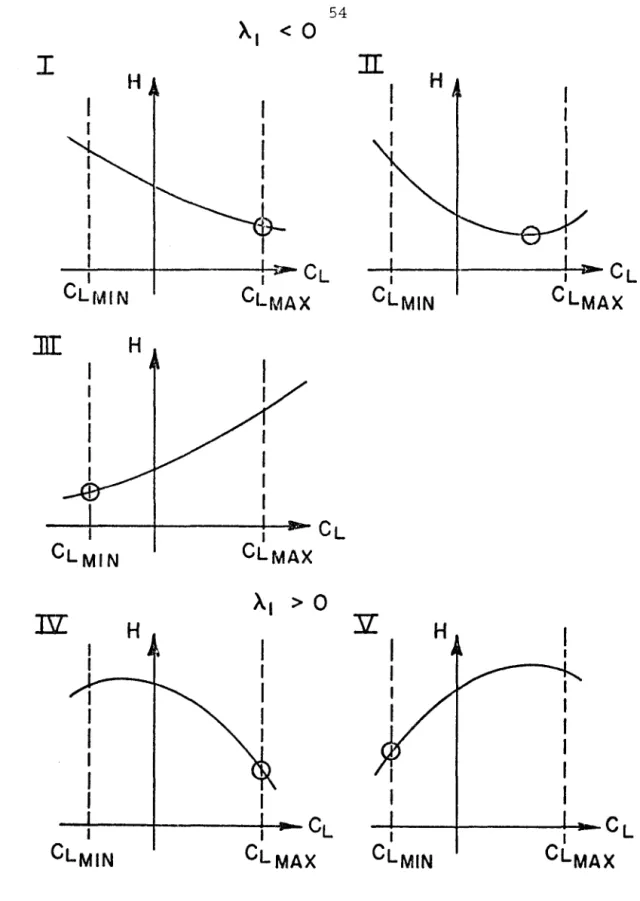
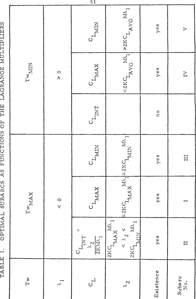
Although this non-lifting arc, which produces the least resistance and thus the greatest excess power, is a special case of the intermediate lifting arcs discussed above, it will be investigated here because of its special physical significance. The fact that the lift is intermediate means that Al < 0 (Tw = Tw . MAX) by analysis in Sections 2. Differentiating the above equation with respect to T gives yrr.
The simple reasoning for the transition I --+ V iITlp is that this transition is possible, if (A. c. In general, the right-hand side of equation CL, given by equation 1, will vanish at the corner, thus contradicting equation 1). Since no terminal constraints have been imposed on the state in the above analysis, any time-optimal maneuver in the vertical plane, and not just loop maneuvers, will consist of these subarcs. assuming this is V, Y or a. equivalent to C.
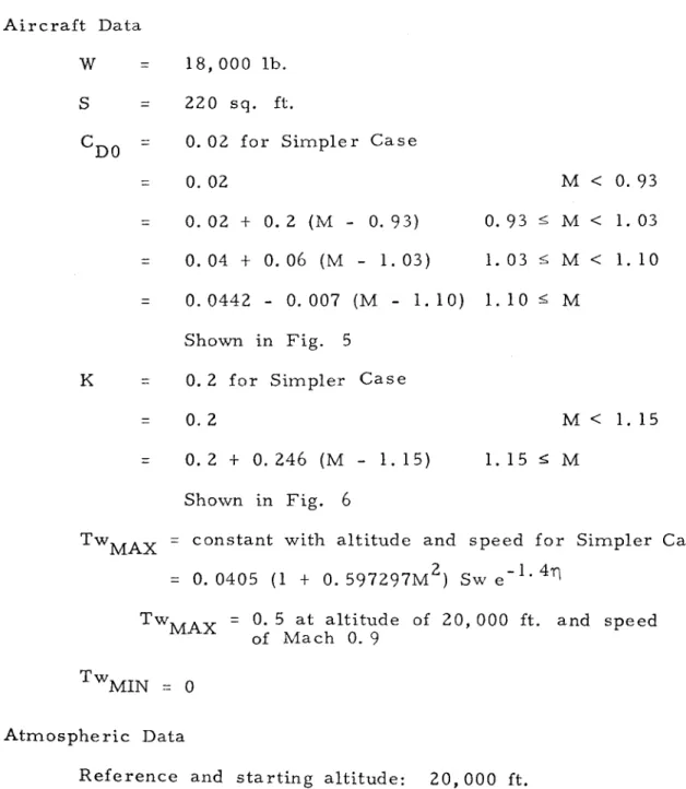
Minimum time solutions consist of paths with maximum thrust and maximum normal acceleration or maximum lift coefficient. In order to obtain the characteristics of a realistic minimum time maneuver, some of the simplifying assumptions made previously will now be removed. DO is a function of Mach number: C. 4) Limitations on normal acceleration due to aircraft structural limitations or the pilot's physiological limits are considered red.
In general, the normal acceleration limitation is only effective when the dynamic pressure (q = iX.PM2) is relatively large. L are more restrictive than the state-dependent limits imposed by the normal acceleration constraint. Intermediate thrust arcs are therefore not optimal in the more realistic case, just as in the simpler case.
This result contradicts the above conclusion regarding Al. Hence a subarc with Tw ::: TWMIN and CL ::: CL.
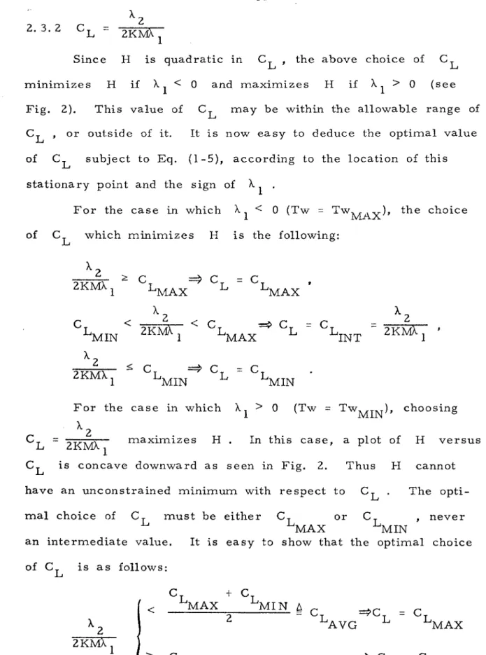
C L AVG
The optimization problem considered here can be expressed as a two-point boundary value problem. The initial time and the initial state are given, but the initial Lagrange multipliers and the terminal time are unknown. Since this two-point boundary value problem does not appear to have an analytical solution, some form of numerical optimization technique must be used.
Making us the fact that A 3 and A 4 are constant and H(T) = -1, an extremal trajectory can be generated by guessing the three quantities (A 1 )in' A 3 and A 4' and integrating differential equations for. The optimal c onb:ol along the trajectory is determined in terms of the state variables and Lagrange multipliers, as described in Part II. A three-dimensional search must then be made for the set of initial parameters which cause the necessary terminal conditions to be satisfied.
If Sf is specified, but ~ is not, the search is two-dimensional because A 4 == 0 The situation is analogous if 'rlf is specified, but Sf is not. Comparing the calculated results for different step sizes, it was found that approximately five hundred integration steps were sufficient to ensure four-digit accuracy at the endpoint. Several other parameters can be considered variable in addition to those we have already considered, for example the weight and wing area of the aircraft and the initial speed and altitude.
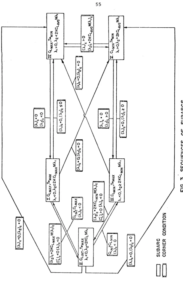
Since it is not known a priori which combination of sub-arcs will yield an optimal solution, exploratory calculations for a minimum time path have been made for case C. Paths with different combinations of sub-arcs, for example I, I-II-I, or IV-I etc. ., were calculated and the performance indices of the maneuvers were compared. Based on these results, the control program for a time-optimal path is not expected to differ much from that of a path with C and.
L MAX Tw MAX ' This conclusion is confirmed by private talks with
An initial speed of Mach O. Because it is not known a priori which combination of subarcs will yield an optimal solution, exploratory calculations have been made for a minimum time path for case C. Paths with different combinations of subarcs, for example I, I-II-I or IV-I etc. were calculated and the performance indices of the maneuvers were compared. This conclusion is confirmed by private conversations with. this limit until the maximum lift coefficient is less than the normal acceleration limit, due to a decrease in dynamic pressure. This suggests how we can make an initial assessment of the one-dimensional search. at that point Subarc I will follow, according to the angle conditions for the transition II - t I. 2-1) because Al must be integrated from the angle, instead of the Ci equation.
Integration to the final point, where Y f = 2li , yields the final value of AI' along with A 2 and other state variables. The control programs along this trajectory correspond to the results of the exploratory calculations and the standard pilot I procedure.
L MAX
RESULTS AND DISCUSSION
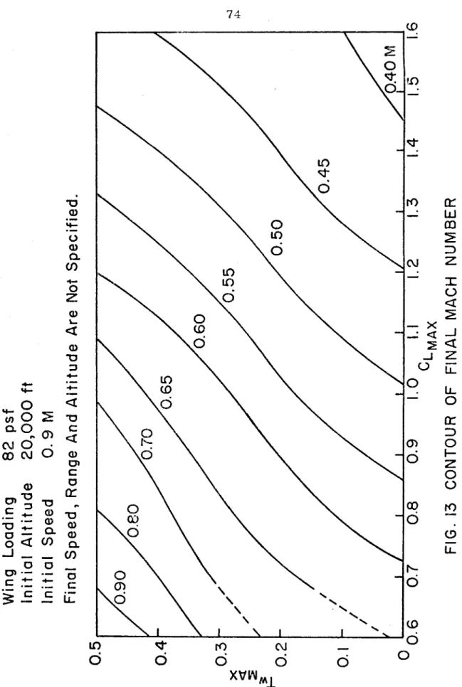
Effects of maximum lift and thrust coefficient on control program. are taken for the case in which final. speed, altitude and range are not specified. Representative histories of control and state variables and Lagrange multipliers for each region are shown in Figs. In the vicinity of the boundary line between points 1 to 2 (regions separating band F), there are three local optimal solutions of types B, E and F, which have different values of the maneuvering time.
This causes a lot of distortion in the intake and duct airflow and causes the engine to stall. The maneuvering time, the height at the top of the loop and the final range are greater in the former than in the latter. MAX constraint has a large effect on the first part of the path, as the initial dynamic pressure is large.
MAX is considered to be 7.33, the structural limit load factor for combat aircraft (22), most of the control history chart does not need to be modified. reduced to 5, major changes must be made, especially in the initial part of the route. Therefore, the effect of n. The MAX limit depends on how long the limit is effective relative to the total time of the maneuver. For given initial conditions, the magnitude effects were C. MAX on the MAX control program. plotted in the control history map, for the case where final speed, range and altitude are not specified. the plane was divided into eleven regions.
One of the other two has acceptable solutions; however, no stationary solutions have yet been found. Tw on MAX time and final min time range.e D'laneUVer are similar. MAX is average, it may be necessary to investigate the dynamic behavior of the inlet and duct airflow, as the thrust changes abruptly from minimum to maximum.
Since the control history ITlap is obtained for a particular combination of wing load, initial altitude and initial speed values, the pattern of ITlap ITlay is affected by changes in these parameters. These include problems with the energy height difference ITlaxiITlization. he = y + ~g, see Appendix B), fuel consumption ITliniITlization and the target pursuit problem, the latter being a differential game problem. Miele, A., "An extension of the theory of the optimal combustion program for level flight of a rocket-powered aircraft," Journal of Aeronautical Sciences, Vol.
CLMIN
CLMIN H
CLMAX
57 ff(sec)
58 ft{sec)
Wing loading 82 psf Initial Altitude 20,000 ft Initial I Speed 0.9 M Final Speed, Range and Altitude not specified.