A Thesis Presented to The Faculty of Alfred University
Optical Properties of Sugar Glass
by
Jocelyn Quintas
In Partial Fulfillment of the Requirements for
The Alfred University Honors Program
May 2022
Under the Supervision of:
Chair: Dr. Alexis Clare - Professor of Glass Science Committee Members:
Dr. Doris Moncke - Associate Professor of Glass Science/Engineering Angus Powers - Professor of Glass
ii Acknowledges
I would like to send my regards to my entire committee: Dr. Alexis Clare, Dr. Doris Moncke, and Angus Powers. Dr. Clare, for being my advisor and mentor since the first day of freshman year till now. Dr. Moncke for teaching me all throughout my time as an undergraduate. Also, Alfred University for giving me the opportunity to meet Angus during GlassArtEngine. Without his approach to the course, I would not have imagined doing a thesis on sugar glass. I would also like to extend a thank you to the graduate students working out of Hall of Glass Science for letting me bother them with questions.
Thank you so much Grace L. for allowing me to rant to you about what I have been doing and for lending me use of your red laser. You’re the best! And the greatest thank you to my family and friends for tolerating me, knowing that I am a handful. Ma, I really appreciate you for being there with me when I needed someone the most and for not allowing me to drop out of the Honors Program.
iii Introductory Statement
I pull out my phone to check the time as the screen flickers to life. It is 4:21 a.m., just how late did I stay up? I take another sip of the cherry-flavored energy drink and glance at the notes I scrawled in my notebook as the cursor hovers over the Google document.
The paper is almost complete—I just need to write a couple more sections, proofread, and print out a final copy to submit it officially. I will have to successfully defend my thesis on sugar glass, and then will I have completed this thesis. Well, I will be done with just this paper. I still need to continue writing my undergraduate thesis on
Mesopotamian glass. That is a whole other can of worms that I will not attempt to cut myself on, as of this movement. At least I do not have to defend that one because, knowing myself, defending a second one would have added a lot more stress than it would have.
Honestly, if freshman me could see me right now as I am pulling consecutive all-
nighters to get both theses done on time, I do not think she would have any pity for me.
I dug my own grave with this one, but hey, at least it is not like I did it consciously…
Right? Who knows. All I know right now is that my head feels like it weighs about a hundred pounds, and my eyes are practically glued shut. My body aches from the long hours of typing, researching, and cross-referencing at the last minute. I've been doing this repetitively for over a week, and it seems that this paper is going to be finished in hours just shy of my deadline. Man, you would think that in my fourth year as an
engineering student, I would be on top of everything? But no. Alas, I seem to only excel at procrastinating and dodging deadlines, and this paper is no exception.
iv
Anyway, back to the topic at hand. I originally intended to use this thesis as a continuation of a research project carried out during GlassArtEngine, an Alfred University course I took during the Fall 2021 semester, my junior year. Since
GlassArtEngine is a course aiming to blend the line between art and engineering. There currently is a growing dissociation between the arts and engineering, which also affects artists and engineers. Each college, Alfred University’s School of Art and Design and the Inamori School of Engineering, have their own curricula on what is taught about glass. This course was crucial for me as a glass student because students from both disciplines who have taken this course have a greater understanding of exploring the boundaries and intersections.
Before taking GlassArtEngine, I previously thought that there is a distinct line between art and science. I have encountered this when I, as an engineering student, have talked with a roommate who is in the arts, about glass. The flow of the conversion is not
naturally smooth since it was awkward, and there was no basic comprehension of what the other is talking about. We have our own language we use with glass, and the use of vocabulary words does not translate over. But now that the course has ended,
communication between the two of us has strengthened because we are now able to communicate our point across.
I decided to continue the project on my own terms. The subject of that project was to initiate investigations into the properties of glass and its color as the result of its surroundings. I really wanted to play around and create sugar glass, sodium silicate (water glass), and other glasses that are hygroscopic. Because of that, I narrowed down on sugar glass as it combined two of the three glasses I was fascinated with. Sugar
v
glass has the ability to pull moisture from its environment. But this posed complications later on in my investigation to figure out the optical properties of sugar glass.
vi
Table of Contents
Acknowledges ii
Introductory Statement iii
List of Tables vii
List of Figures viii
Abstract ix
Introduction 1
Glass 1
Sugar Glass As a Glass 1
Sugar Glass 2
Chemical Durability & Solubility 2
Optics 3
Diffraction Gratings 4
Experimental Procedure 6
Synthesis of Sugar Glass 6
Chemical Durability & Solubility 6
Optics 6
Diffraction Gratings 7
Ultraviolet-visible-near-infrared (UV-Vis-NIR) Spectroscopy 10
Results & Discussion 11
Synthesis of Sugar Glass 11
Chemical Durability & Solubility 12
Optics 14
Diffraction Gratings 16
UV-Vis-NIR Spectroscopy 17
Conclusions 20
Suggestions For Future Work 21
Literature References 22
Appendix I – Commercial Diffraction Grating Sheets 24
vii List of Tables
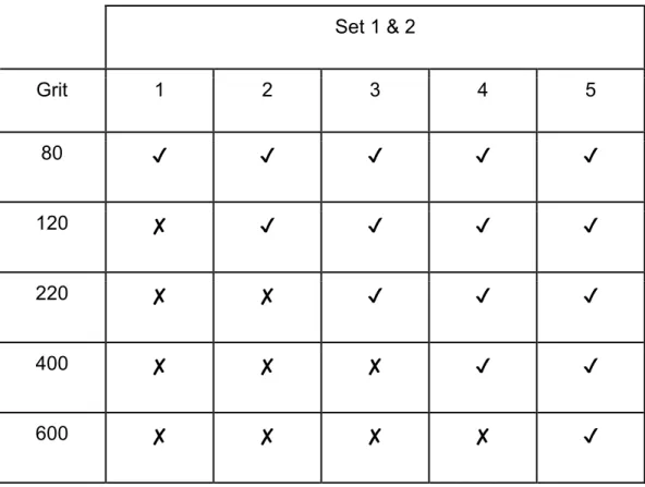
Table 1. Grit used for each glass in set 1 and 2. 9
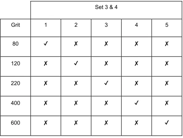
Table 2. Grit used for each glass in set 3 and 4. 10
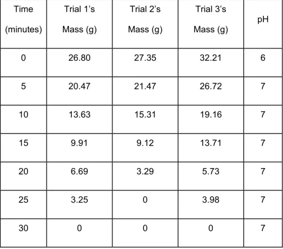
Table 3. Trials 1-3: pH and mass (g) over time for sugar glass. 13
viii List of Figures
Figure 1. Set up for cylindrical lens to generate a light sheet. 4 Figure 2. Schematic of a diffraction grating. 5 Figure 3. Set up for spreading laser light into a sheet. Not drawn to scale. 7 Figure 4. Set 1 (upper left), Set 2 (upper right), Set 3 (lower left), and Set 4 (lower right)
with increasing grit going from left to right. 8 Figure 5. 3 glass slides, scratched with a dull knife (top), a sharp knife (middle), and
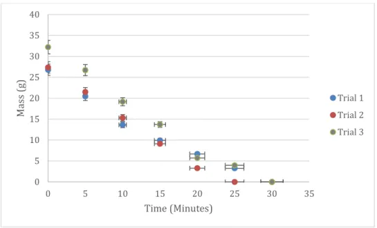
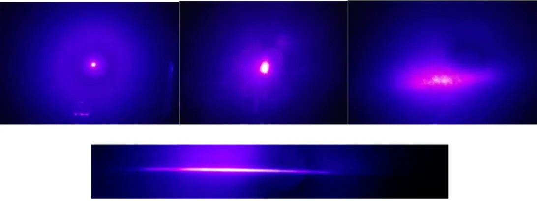
cement (bottom). 8 Figure 6. 3 sugar glass trials of mass (g) and pH over time. 14 Figure 7. Blue laser: Light from laser (upper left), light through sugar glass (upper
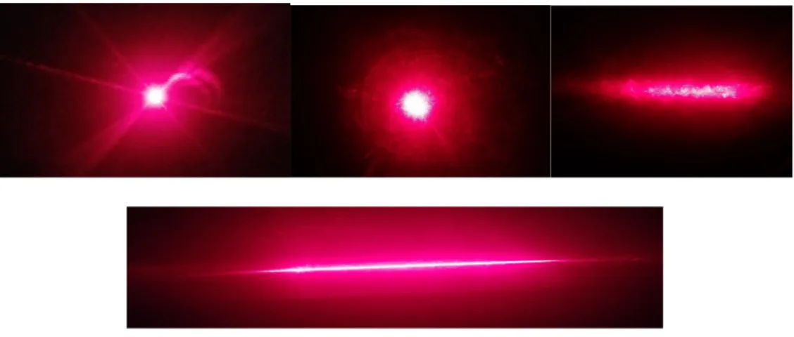
middle), light through cylindrical lens and sugar glass (upper right), and light through a cylindrical lens (bottom). 15 Figure 8. Red laser: Light from laser (upper left), light through sugar glass (upper
middle), light through cylindrical lens and sugar glass(upper right), and light through a cylindrical lens (bottom). 16
Figure 9. UV-Vis-NIR spectra before and after lasers on sugar glass. 19
ix Abstract
Sugar, like silicates, can be heated to molten temperatures and become glass once cooled. Confectioneries use a mixture of several sugars to create hard candies, and a sugar glass is another name for this. Sugar glass, like traditional glass, cools and solidifies into a transparent material. Depending on ingredients used or the range the sugar was cooked for, its properties change. If the sugar syrup was left too long and went past its hard-crack stage, then the resulting sugar would be caramel, with a sugar concentration of 100%. For this study, optical properties of sugar glass were
investigated. Optically, the sugar glass behaved similarly to that of commercial glass.
Light, from a blue and red laser, could interact with the surface of the glass to generate predictable outcomes. The glass could interact with its own version of a sheet of light with the help of a cylindrical lens. It is achievable to create a diffraction grating out of sugar glass because of its similar behavior to that of glass. The diffraction grating sheet’s grooves transferred over to the sugar glass when used as a mold. Waves of visible color, at its respective wavelength, were observable when shining white light.
However, because of the grating’s defining qualities, that of specific sized and spaced apart grooves, it was not achievable using homemade diffraction grating molds. It would require proper tools to embed such surface topography.
1 I. Introduction
Glass
"What is glass?" is the usual question asked on the first day of class. It is a silly question, really. Everyone has seen glass before; so, when students respond with saying glass is a hard, yet brittle solid that is transparent and made from sand. They would be partly correct in their answer. Yet in glass science and engineering, glass is a lot more to it than a simple definition.
Microscopically, the structure of an amorphous solid lacks long-range order. Unlike single crystals, where the arrangement of atoms are packed neatly and linearly, atoms within amorphous solids move randomly out in a disorderly fashion1-3. It is important to distinguish that all glasses are amorphous solids, but not all amorphous solids are glasses. Other definitions of glass include the existence of a glass transition
temperature range over which materials transform from behaving like a viscous liquid to a glass solid4,5.
Sugar Glass As a Glass
The term “hard candy,” in the confectionary industry, refers to the process in which sugar syrups are boiled to high enough temperatures. Hard candies are sugar glasses because, like glasses, they go through a glass transition temperature and have an amorphous structure. Its glass transition temperature changes from having a viscous characteristic of that of a liquid syrup to that of a solid glassy state. The range can be quantitatively defined as it depends on the mixture’s composition6-8. Hard candies can either be classified as crystalline or amorphous, depending on how and what is used in
2
creating the hard candy. In order to have an amorphous structure, a second type of sugar, often corn syrup, is added alongside the base sugar. Corn syrup is able to prevent crystallization because of the confusion principle; excess elements in the melt increase the chance of forming a glass because it enforces a disordered pattern9.
Sugar Glass
Granular sugar is used in confectioneries, one must take precaution when mixing and dissolving this type of sugar. Due to its larger grain size, compared to that of powdered sugars, the crystals take longer to dissolve within water. Proper water to sugar ratio and holding the molten sugar at high temperature will ensure homogeneity in the candy. As the mixture reaches the temperature range where it is at its hard crack stage, 149 - 154
°C, most of the water content has already been boiled off6,10. The percentage of water content would be approximately 2 - 3%. The sugar is at a concentration that would reach 99%, and at this range, it is much easier to heat it past the hard crack stage. The temperature quickly rises in relation to its water content.
Chemical Durability & Solubility
Sugar glass is naturally hygroscopic, being able to absorb water vapor from its surrounding environment. This ability can lead to detrimental effects to the candy.
Absorption of moisture through the surface of the sugar glass leads to the degradation of its structure. Residual moisture will permanently affect its surface. Macroscopically, the hard candy appears to be unaffected, but the texture of the candy changes from a solid surface to a sticky one. Diffusion of water from the surface of the candy to the center causes stickiness. Storing the sugar glass in an environment where it is below its
3
glass transition temperature will not cause instability. If the temperature rises above that point, then it will become unstable by being sticky and less viscous9,10.
Optics
Light can be absorbed, reflected, transmitted, or even scattered when interacting with a glass surface. Matching the energy of the wavelengths of light to that of the energy within the glass will lead to absorption, never to be transmitted as light. Differences between reflection and refraction would be light being reflected by a polished surface, will bounce right off at the same angle it came in. Light changes angle when passed through the interface and into a different medium, is the measure of refraction11. For refraction, the speed of light in glass is slower than the speed of light in air. The re- emission of light through a different medium may not contain the same energy as some of the energy can be absorbed. A change in energy when being transferred by
wavelengths leads to re-emitted light visibly appearing dimmer12,
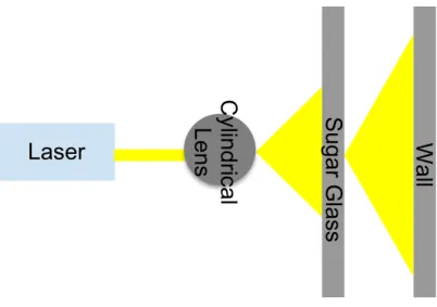
A solid rod of glass can be used for beam shaping because the glass will act like a cylindrical lens. In one direction, the cylindrical glass diverges the incident beam, causing the light from the laser to spread out horizontally, on the x-axis13-16. Spreading the laser light out creates a flat sheet of visible light, as seen in Figure 1.
4
Figure 1. Set up for cylindrical lens to generate a light sheet.
Diffraction Gratings
Diffraction gratings disperse light into its component wavelengths. Visually, these gratings separate white light's energy into wavelengths within the visible range. Thus, causing a rainbow effect when diffracted light is shined onto a reflective surface. On the surface of a grating are microscopic grooves, which act as a way to reflect light. Figure 2 illustrates a reflection grating where the diffracted and incident rays are on the same side. If the diffracted and incident rays were on opposite sides, that would have been a transmission grating17.
The process and method in which they are fabricated must not introduce defects, as defects significantly lowers the transmission of visible spectra. Efficiency and precision of the spacings and groove shape, for a diffraction grating, is the ratio between the intensity of light being diffracted to the intensity of the incident light’s energy. With higher efficiency, stray light from the transmission of the spectra can be prevented as it causes the light to focus and not diffuse into smaller wavelengths18-20.
Laser Sug ar G las s W all
C ylin dr ica l Len s
5
Figure 2. Schematic of a diffraction grating18.
6 II. Experimental Procedure
Synthesis of Sugar Glass
The synthesis of sugar glass consisted of 237 ml of water, 237 ml of corn syrup, and 332 g of granular sugar. A ratio of 1:2 was used for the amount of water to granular sugar. All three ingredients were placed into a pan to heat, and the candy mixture heated to the hard crack stage of sugar, 154°C. A candy thermometer was used to monitor the temperature and to prevent caramelization of sugar.
Chemical Durability & Solubility
The pH of the water was inspected before adding the sugar glass. This will serve as a reference point to compare over the elapsed time. When the starting point was noted, the samples of sugar glass were examined by weighing them prior to placing the
samples into a plastic, tight sealed container with deionized (DI) water alongside the pH paper. The measurement of the pH of the water was recorded every 10 minutes, as well as the mass of the sample. Once there no longer sugar glass present, meaning it has completely dissolved, the final pH was recorded.
Optics
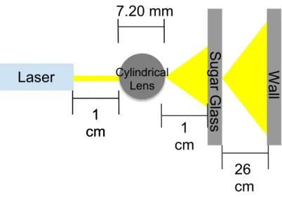
Blue and red lasers of wavelengths 405 nm ± 10, 650 nm ± 10, respectively, were each taped to a surface parallel to the ground. Sugar glass, with a thickness of 3.08 mm, was taped perpendicular to the ground, 2 cm from the front of the laser. The distance from the wall to the sugar glass was 36 cm. On the other set up, a cylindrical lens, with a thickness of 7.20 mm, was placed between the laser and sugar. Both sides have a distance of 2 cm, and the layout can be seen in Figure 3.
7
Figure 3. Set up for spreading laser light into a sheet. Not drawn to scale.
Diffraction Gratings
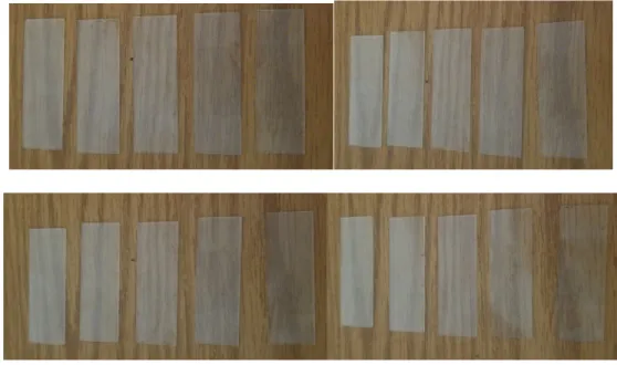
20 microscope slides, made of soda-lime silicate (SLS) glass, were hand lapped using 80 - 600 grit. The glass was slid across a slurry of abrasive particles in a left-to-right pattern to prevent deviation from embedding parallel lines. There were 4 sets of 5 glass slides (Figure 4); the first and second set were ground for 6 and 5 minutes, respectively.
The remaining sets were lapped for 2 minutes. Sets 1 and 3 were lapped in the same pattern, where all the slides in each set were polished to 80 grit. Leaving the first slide alone in each set, the remaining 4 slides were lapped to 120 grit. And this pattern continued until the fifth glass slide was consecutively polished from 80 to 600 grit. Each of the five slides in the last 2 sets corresponded to its respective grit, i.e., each slide was lapped once per grit (Table 1 and 2).
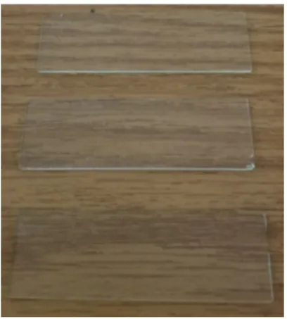
3 microscope slides (Figure 5) were scratched with a dull knife, a sharp knife, and cement. 2 CDs and movies were cleaned to have a transparent disk as both front and
Laser
Sug ar G las s W all
cm 1 1
cm
26 cm cm 1
7.20 mm
Cylindrical Lens
8
back will be used. The top film was removed from the remaining base by tape (not pictured).
Figure 4. Set 1 (upper left), Set 2 (upper right), Set 3 (lower left), and Set 4 (lower right) with increasing grit going from left to right.
Figure 5. 3 glass slides, scratched with a dull knife (top), a sharp knife (middle), and cement (bottom).
9
Table 1. Grit used for each glass in set 1 and 2.
Set 1 & 2
Grit 1 2 3 4 5
80 ✔ ✔ ✔ ✔ ✔
120 ✘ ✔ ✔ ✔ ✔
220 ✘ ✘ ✔ ✔ ✔
400 ✘ ✘ ✘ ✔ ✔
600 ✘ ✘ ✘ ✘ ✔
10
Table 2. Grit used for each glass in set 3 and 4.
Set 3 & 4
Grit 1 2 3 4 5
80 ✔ ✘ ✘ ✘ ✘
120 ✘ ✔ ✘ ✘ ✘
220 ✘ ✘ ✔ ✘ ✘
400 ✘ ✘ ✘ ✔ ✘
600 ✘ ✘ ✘ ✘ ✔
Ultraviolet-visible-near-infrared (UV-Vis-NIR) Spectroscopy
UV-Vis-NIR spectra were analyzed on a single sugar glass, with a thickness of 3.08 nm, were recorded on a spectrophotometer, Lambda950 (Perkin Elmer, US) using
absorbance measurements from 200 to 3,000 nm. A blue and red laser was swept across the sugar glass in a Z-pattern, starting at the top left and moving back and forth.
This movement was done to see if the interaction changed the area where the light was swept across. The surface where the laser hit the sugar glass did not overlap with the path of the other laser. The sample was not polished before doing measurements as it would have dissolved.
11 III. Results & Discussion
Synthesis of Sugar Glass
The sugar glass was carefully poured over the microscope slides. Pouring slowly prevented overflowing the sugar glass, meaning the glass did not have too little or too much resistance to flow when poured. Once the sugar cooled, it was then pulled off from the diffraction grating mold.
There was resistance from removing the sugar off because on some slides, the two layers were stuck to one another. Aiming to separate the two, multiple sharp
instruments were wedged between the two, and this situation gave rise to two things occurring. One is that the sugar glass, cracked into pieces, where the candy was broken into several tiny pieces. Or it was not workable to free the sugar glass from the
diffraction mold. Both cases happened multiple times, and with no correlation between grit and not breaking free.
This did not occur as much as it occurred with the remaining 8 SLS glass molds. I had thought this may have resulted from the surfaces not going through the lapping process.
I originally thought this because the smoothness from a pre-polished surface could have allowed the two to separate. Two smooth surfaces, when coming into contact with each other, have a higher chance of sticking to one another. Because with more contact points, the two surfaces share, the higher the chance it would have caused the sugar to stick to the microscope slide. Therefore, it is not logical to say that the polished surface of the slides caused the sugar to adhere to it.
12 Chemical Durability & Solubility
Sugar glass is unstable at temperatures below its glass transition. Because of this, sugar glasses react with moisture in the air and destabilizes. The first stage of chemical durability would be the change in texture of the sugar glass. Before it had time to react with the water in the air, the sugar glass was hard and solid. Once re-emerging from being within water, the surface area of the glass was sticky to the touch.
Durability and solubility tests were performed with 3 sugar glasses with an initial mass of 26.80, 27.35, and 32.21 g. Data from the 3 trials (Table 3) show a linear response rate at which the sugar glass dissolves over time. Figure 6 shows a data trend of rapid decrease in mass over time, and this trend was present for all 3 trials of the sugar glass.
A maximum pH of 7 occurred after the starting time of 0 minutes. Because at time zero, the pH of the water was used as a reference point to see if the dissolved sugar glass would affect it.
13
Table 3. Trials 1-3: pH and mass (g) over time for sugar glass.
Time (minutes)
Trial 1’s Mass (g)
Trial 2’s Mass (g)
Trial 3’s
Mass (g) pH
0 26.80 27.35 32.21 6
5 20.47 21.47 26.72 7
10 13.63 15.31 19.16 7
15 9.91 9.12 13.71 7
20 6.69 3.29 5.73 7
25 3.25 0 3.98 7
30 0 0 0 7
14
Figure 6. 3 sugar glass trials of mass (g) and pH over time
Optics
Before the blue and red lasers were shone through the cylindrical lens, a picture of the lasers was taken as is (Figure 7 and 8). The light from both the lasers was focused in one spot. However, the picture for the red laser did not translate well from what was seen to what was captured. Take note that the red laser behaved the same way as the blue one. Disregard the linear rays seen as that is an artifact from the camera (Figure 8). Under 5 minutes of the laser beam, the light transmitted from the sugar glass was dispersed, causing the wavelengths emitted from the laser to scatter. Instead of having the beam of light focused within a small area, the light transmitted from the sugar glass covered more surface area.
Figures 7 and 8 show when the cylindrical lens was in the laser’s path, it vertically flattened and horizontally stretched the light. The beam of light transformed from being circular to a thin sheet of light. Some of the light from the laser is still light being
0 5 10 15 20 25 30 35 40
0 5 10 15 20 25 30 35
Mass (g)
Time (Minutes)
Trial 1 Trial 2 Trial 3
15
dispersed, but now in a faint elongated circular pattern. Knowing the fact that shining a laser through sugar glass caused a scattering effect, and light sheets form through the use of cylindrical lenses, it is possible to deduce that using both will cause the light to behave combine both optical effects. Placing the cylindrical lens between the laser and sugar glass brought about a lack of a long thin sheet. Instead, it horizontally shortened the sheet as seen in Figure 7, upper right. There was a more prominent elliptical shape instead of a thin sheet.
Figure 7. Blue laser: Light from laser (upper left), light through sugar glass (upper middle), light through cylindrical lens and sugar glass (upper right), and light through a
cylindrical lens (bottom).
16
Figure 8. Red laser: Light from laser (upper left), light through sugar glass (upper middle), light through cylindrical lens and sugar glass (upper right), and light through a
cylindrical lens (bottom).
Diffraction Gratings
Usable sugar glass shards were analyzed to determine if the diffraction grating lines were transferred. Four different light sources were shone onto the samples: a red and blue laser, incandescent, and an LED light. None of the samples showed characteristics of transferring the diffraction grating pattern. Meaning, waves of visible colors, at its respective wavelength, were not observable. Light, from the lasers, would not shine through the sugar glass as though they were not being transmitted through a diffraction grating.
It did not happen the way it was predicted because of factors that were not in our control or those that were and did not meet specifications. First, the residual moisture content within the glass was a dependent variable that was not taken into consideration.
Leftover moisture will affect the consistency of the candy’s surface. There has been an
17
inverse relationship between residual moisture and hardness of the sugar. As the percentage of moisture decreases, the hardness of the resulting sugar will increase.
Looking back at what happened between the mold and the sugar glass, a softer texture would have deterred the two from adhering. Such a texture was detrimental because the softer sugar glass did not maintain the specifications crucial for a diffraction grating.
Because of the gradual decrease in viscosity over temperature and time, the transition from a malleable state to a permanent state would have caused the desired molded shape to deform.
Paired with excess humidity from the environment, the surface of the sugar glass would have been affected. It too would have led to the structure of the surface to become unstable, and the lapped ridges would not have survived. Disintegration of sugar will be further examined under the section Chemical Durability & Solubility. Thus, why, in principle, it is achievable to create a diffraction grating without commercial means.
Examples of using a diffraction grating sheet as a mold can be seen in Appendix I.
UV-Vis-NIR Spectroscopy
Only one sample of sugar glass was used to do analysis on the UV-Vis-NIR spectrum.
The color of the sugar glass was that of yellow-tan, and when light passes through a yellow-colored glass, wavelengths of its complementary color are being absorbed.
While looking at the wavelengths from 350 to 1400 nm (Figure 9), the signals from that range have steps because it is caused by the change in the monochromator.
A monochromator is an optical device used to select a narrowed component of the light source’s spectrum. This allowed for a desirable band of wavelength to be aimed at a
18
sample. It will illuminate the sample by shining light on it. The detector will then record the emitted light from the sample. The higher the quality of the glass, the change in the monochromator is not seen within the spectra because the surface of the glass is smooth. Unfortunately, because sugar glass can readily dissolve with heat, polishing it would be difficult since the friction between the two surfaces can produce heat. Thus, destroying the sample in the process.
An alternate way, instead of polishing the glass, would be to measure it very slowly, but that does not guarantee to remove the change in the monochromator. If the signals would have happened less frequently than seen, then it could have been an artifact, and therefore an error. An artifact is an error introduced by the involvement of the
instrument’s equipment or technique used.
Based on Manley, the absorbance peaks within the range of 1440 - 1470 and 1920 - 1940 nm, respectfully, correspond to the molecular bonds of moisture. Specifically, the range from 1440 to 1470 nm is where the first overtone of O-H happens, the bond of O- H stretches in water. From 1920 to 1940 nm is where the O-H stretches and then deforms, the second overtone20. An explanation for why the water bands appeared in the UV-Vis-NIR spectra would be that, within a sugar molecule, there are several O-H bonds. A sugar molecule is made up of numerous carbons, hydrogens, and oxygens.
And therefore, water bands will most likely still appear as moisture within the sugar glass even if the sugar glass was made under vacuum.
19
Figure 9. UV-Vis-NIR spectra before and after shining lasers on sugar glass.
20 IV. Conclusions
In principle, diffraction gratings can be created using a transparent substrate and tooling to create grooves. Therefore, it is possible to use sugar glass as an optical tool that can separate the wavelengths of light into its components. The rainbow effect that is
associated with such gratings may happen using sugar glass. There are also obstacles to overcome since sugar glass is not the most suitable for acting as a diffraction grating.
It is doable, yes, but one must account for the glass’s chemical durability and being readily soluble. Moisture can affect the surface of the sugar glass, and a change in temperature within the environment can destabilize the structure of the glass.
That being said, the optics of sugar glass behave similarly to that of traditional glass. It can affect the shape of laser beams, even when it is paired with a cylindrical lens. Just by itself, sugar glass can defocus and disperse wavelengths of the laser beam.
Scattering of the light rays allowed the light to hit more surface area. With a cylindrical lens, the light sheet no longer was as long and flat because it shorted the area in which light was scattered, achieving a shape of a narrowed ellipse.
21 V. Suggestions For Future Work
Having the means to properly engrave grooves within sugar glass would be a step in the right direction. Right now, I have used anything I could get my hands on in order to tool in parallel lines on the surface of the glass. Instead of using a microscope slide to act as a mold for a diffraction grating pattern, it may be easier to put grooves directly via laser cutting. Sugar glass is dissolvable within the water, so using water laser cutting would be out of the question. Furthermore, using lasers to see the interaction between a diffraction grating and a laser can expand on the optics of sugar glass. Spectral analysis using a spectrophotometer can see how light interacts with a sugar glass diffraction grating.
22 VI. Literature References
1. Richet, P.; Conradt, R.; Takada, A.; Dyon, J. Encyclopedia of Glass Science, Technology, History, and Culture; The American Ceramic Society, 2021. DOI:
10.1002/9781118801017
2. Vogel, W. Glass Chemistry, 2nd ed.; The American Ceramic Society, Inc., 1994.
3. Zanotto, E. D.; Mauro, J. C. The Glassy State of Matter: Its Definition and Ultimate Fate. J. Non-Cryst. Solids. 2017, 471, 490-495.
4. Musgraves, J. D.; Hu, J.; Calvez, L. Springer Handbook of Glass. Springer, 2019.
5. Varshneya, A. K. M.; J. C., Fundamentals of Inorganic Glasses. 3rd ed.; Elsevier, 2019.
6. Seo, J. A.; Kim, S. J.; Kwon, H. J.; Yang, Y. S.; Kim, H. K.; Hwang, Y. H., The Glass Transition Temperatures of Sugar Mixtures. Carbohydr Res. 2006, 341 (15), 2516-20.
7. Cummins, H. Z.; Zhang, H.; Oh, J.; Seo, J.-A.; Kim, H. K.; Hwang, Y.-H.; Yang, Y. S.; Yu, Y. S.; Inn, Y., The Liquid–glass Transition in Sugars: Relaxation Dynamics in Trehalose. J. Non-Cryst. Solids. 2006, 352 (42), 4464-4474.
8. Cornacchia, L.; Roos, Y. H., Sugar Crystallization and Glass Transition as Destabilizing Factors of Protein-Stabilized Emulsions. Food Biophysics. 2012, 7 (1), 93-101.
9. Edwards, W. P. The Science of Sugar Confectionery; The Royal Society of Chemistry, 2000.
10. Hartel, R. W.; Elbe, J. H. v.; Hofberger, R. Confectionery Science and Technology, 1 ed.; Springer: 2018; p. 536.
23
11. Loudon, R. The Quantum Theory of Light; Clarendon Press, 1983.
12. Smith, A. M. Descartes’s Theory of Light and Refraction : a Discourse on Method;
American Philosophical Society,1987.
13. Dickey, F. M. Laser Beam Shaping: Theory and Techniques, 2nd ed.; CRC Press, 2014.
14. Sirohi, R. S. Optical Methods of Measurement: Wholefield Techniques; Taylor and Francis Group, LLC, 2009.
15. Laskin, A.; Laskin, V. Beam Shaping to Generate Uniform "Laser Light Sheet"
and Linear Laser Spots. Proc SPIE. 2013.
16. Zhang, Y.; Bai, J. Simple and High Efficient Optical Trapping Using a Cylindrical Lens and a Single Plane Wave of Incidence. Opt. Commun. 2008, 281, 4824- 4828.
17. Taylor, C. Diffraction; A. Hilger, 1987.
18. Palmer, C.; Loewen, E. Diffraction Grating Handbook; Newport Corporation, 2005.
19. Davis, S. P. Diffraction Grating Spectrographs; Holt, Rinehart and Winston, 1970.
20. Manley, M. Near-Infrared Spectroscopy a Hyperspectral Imaging: Non- Destructive Analysis of Biological Materials. Chem. Soc. Rev. 2014, 24.
24
VII. Appendix I – Commercial Diffraction Grating Sheets
Figure 1. Sample 1 at different angles. White light’s waves of visible colors, at its respective wavelength observed.
Figure 2. Sample 2 at different angles. White light’s waves of visible colors, at its respective wavelength observed.
`
Figure 3. Sample 3 at different angles. White light’s waves of visible colors, at its respective wavelength observed.