The growing demand is challenging data center operators to manage data center resources. In addition, some current challenges and future work in modular data center system are described. 4 RESULTS AND DISCUSSIONS 45 4.1 Uptime Institute Level Topology Case Study 45 4.1.1 Uptime Level I – Core Data Center Site Infrastructure.
General Introduction
Importance of the Study
An important part of this study is to show the benefits that have been associated with the implementation of a modular data center in terms of design and construction, power density and PUE, scalability, efficiency, mobility and layout, as well as startup and operations, etc. modular capabilities have also been enhanced to provide cost-effective storage and end-to-end data management solutions for businesses.
Problem Statement
Aims and Objectives
Scope and Limitation of the Study
In general, the design of a data center is determined by its components, and the power load profile also depends on the type and consumption of the components. As with most studies, the design of the current study is subject to limitations. First, due to the limitation of time for this study and the lack of real information and resources of the real user feedback about the modular data center, the data collection and real user feedback to have a comprehensive understanding of how modular data helps the organizations and advantage over the traditional data center is difficult to access and is extremely limited.
Contribution of the Study
If a data center is located in a cold area and uses natural cold air for heat transfer, the cooling system must only consist of a few fans for ventilation. Modular data centers deliver the same quality and capacity at a lower cost and in a fraction of the time. This is descriptive research, with this research the importance of data center, the importance of power distribution in a data center and the modern expectation of implementation of a data center by an organization will be brought out.
Outline of the Report
So the shorter the period to start a data center, the sooner the business can make data-driven decisions.
Introduction
Literature Review
Building modular data centers off-site has significantly reduced project learning times because all systems can be pre-assembled and tested simultaneously during construction of the developer's building. In addition to the relatively short lead time, another significant advantage of modular data centers is that they are cost-effective due to their flexibility, simplicity and security. It is concluded that the efficiency achieved by the modular data centers simply cannot compete with traditional brick and mortar construction.
What is Data Centre?
Importance of Data Centre
The flexibility and advantages of modular construction can simplify and shorten the time frame of data center projects from planning to commissioning. This is one of the reasons for the catalyst for the development of modern data centers. A case study will be used to describe the different tiers of a data center and compare it to a modular data center.
Research Work Plan May
Evolution of Data Centre
Modular data centers use tightly coupled array cooling, which greatly improves cooling efficiency. As power consumption in data centers increases, a more efficient and energy-saving cooling system is required. In addition, the use of clean energy, such as wind and solar energy, is increasingly used in data centers.
Types of Modern Data Centre
- Hyperscale Data Centre – Cloud Data Centre
- Colocation Data Centre
- Wholesale Colocation Data Centre
- Enterprise Data Centre
- Telecom Data Centre
- Edge Data Centre
It is possible that certain parts of the data center are divided over different parts of the company. An enterprise data center can be scaled from ten cabinets up to 40 MW. This type of data center requires high connectivity as they are built to deliver content, mobile services and cloud services.
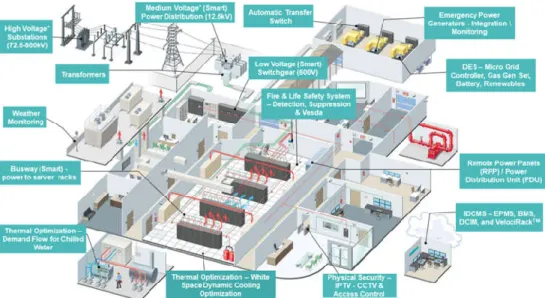
Main Infrastructure of Data Centre
- Power Supply System
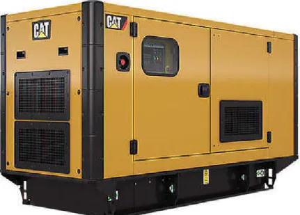
- Diesel Generator and Automatic Transfer Switch
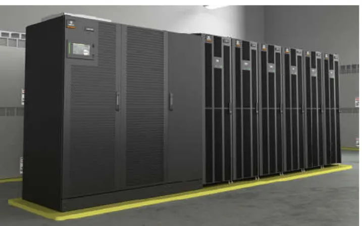
- Uninterruptible Power Supply (UPS)
- Back Up Battery
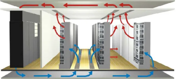
- Cooling System
- Precision Air Conditioner
- Ventilation System
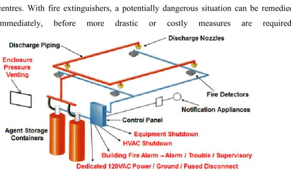
- Fire Fighting System
- Fire Detection System – Smoke / Heat / Flame Detectors
- Fire Extinguishing System – Fire Extinguishers and Total Flooding Fire Extinguishers System
- Surge Protection System
- Ground Protection System
- Cabinet System
- Precision Air Supply Cabinet
- IT Device Cabinet
- Supporting Facilities of Data Centre
- Holding Area
- Staging Area
- Computer / Server Room
- Media Storage Area
- UPS Room
- Battery Room
- Service Corridor
- Standby Generator Set Room / Area
- Meet-Me / Entrance Room
- Security Room
- NOC (Network Operations Control)
- Raised Floor
- Lighting
- Security System
- Access Control
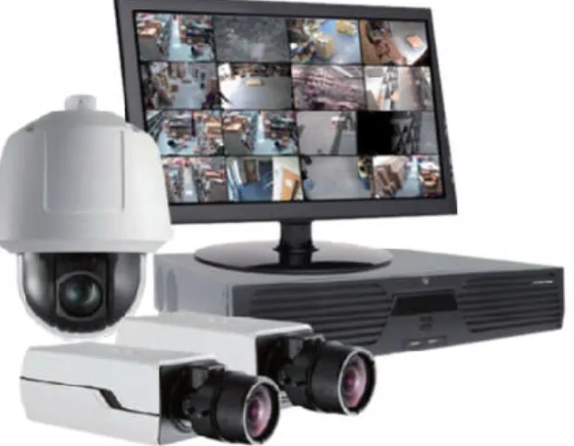
- CCTV Closed-Circuit Television
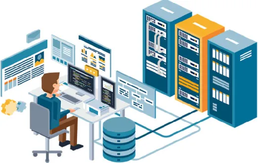
- Management and Monitoring System
- Infrastructure Management
- Power and Environment Monitoring
- Structured Cabling System
- Cable Management System
- Copper Cables
- Fibre Optic Cables
An emergency generator can be located to carry the load on data center components, as well as all essential support equipment in the event of a power outage. With the proper planning of a power cooling system, a large potential for energy savings can be anticipated without compromising the cooling efficiency of the data center's existing air conditioning system. The primary goal of a data center fire protection system is to contain a fire without endangering the lives of employees and to minimize downtime.
The main goal of air conditioning in a data center is to minimize air mixing. This standard is intended to standardize dimensions to ensure compatibility and flexibility in the data center. Do not unpack and place boxes in the data center itself, as this will spread dust.
Security components in a data center must be considered separately, but at the same time must follow a comprehensive security policy. Physical security includes the processes, strategies and systems used to protect the data center from external intrusions. Data center equipped with video surveillance will definitely help in increasing the security of the data center.
The purpose of a DCIM is to provide comprehensive monitoring of a data center's performance so that energy, equipment and floor space can be planned and used as efficiently as possible. The monitoring tools are specific to environmental factors such as:. i) Temperature – Overheating is one of the biggest risks for servers in a data center. Proper cable management in data centers can prevent unsafe environments caused by restricted airflow to cabinets.
- Uptime Tier I – Basic Data Centre Site Infrastructure .1 Fundamental requirement
- Performance confirmation test
- Operational impacts
- Uptime Tier II – Redundant Site Infrastructure Capacity Components .1 Fundamental requirement
- Performance confirmation test
- Operational impacts
- Uptime Tier III – Concurrently Maintainable Site Infrastructure .1 Fundamental requirements
- Performance confirmation test
- Operational impacts
- Uptime Tier IV – Fault Tolerant Site Infrastructure .1 Fundamental requirements
- Performance confirmation test
- The operational impacts
- Data Centre Standards and Regulations
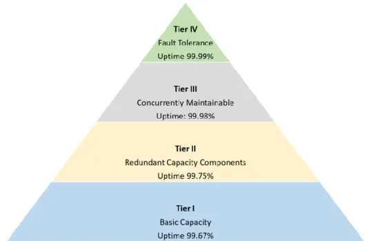
A basic Tier I data center has no redundant capacity components and a single, non-redundant distribution path that powers the entire data center. Operation and human error of the site's infrastructure components will cause disruption of the data center without delay. ii) Any sudden failure or malfunction in the capacity of components or distribution elements will affect the overall critical environment. iii). A Tier II data center that consists of components with redundant capacity and a single, non-redundant distribution path that powers these IT devices.
A Tier III data center is both well maintained and equipped with redundant capacity components with multiple independent distribution paths serving them. A fault-tolerant data center is equipped with multiple, physically isolated systems that provide redundant capacity components and multiple and diverse active distribution paths that simultaneously serve the critical environment. However, this maintenance configuration does not affect the level rating achieved during normal operation. v) However, operation of the fire alarm, fire extinguishing or emergency power function may cause disruption to the data center.
The first and currently the only official accredited data center standard is ANSI/TIA-942. Both the ANSI/TIA – 942 and the Uptime Institute standards are standards and regulations for data center redundancy, reliability, and availability, while no specific standards exist only for subcomponents that can be used to evaluate the subcomponent(s) present in the data center. These standards are not always specific to data centers and therefore more stringent requirements may need to be met when it comes to data center use.
Below are some standards for data center sub-components that are commonly used and met in Malaysia.
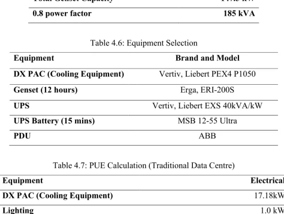
Power Usage Efficiency (PUE)
Calculation of PUE
PUE is the ratio of the amount of energy required to operate and cool a data center to the amount of energy consumed by IT equipment in the data center. Therefore, for an easier calculation, the energy consumption of the facility and IT equipment is required.
DATA CENTRE ENERGY CONSUMPTION
Case Study of Uptime Institute Tier Topology
- Uptime Tier I – Basic Data Centre Site Infrastructure
- Uptime Tier II – Redundant Site Infrastructure Capacity Components
- Uptime Tier III – Concurrently Maintainable Site Infrastructure
- Uptime Tier IV – Fault Tolerant Site Infrastructure
Based on Uptime Tier Topology below is the case study to show how the power and cooling redundancy is implemented based on different Tier Standards. It is assumed that the basic mechanical and electrical infrastructure is designed for a small data center with 10 nos. Based on the above design criteria, below study will be conducted to compare different redundancy based on different Tier Standards.
A Tier I data center is the basic level of capacity with infrastructure that supports IT racks for an office environment and beyond. The Tier II data center has redundant capacity in components, especially power and cooling, to provide better maintenance planning and security against unplanned disruptions. The Tier II data center serves a critical environment that requires the facilities team to shut down components to perform maintenance.
The Tier III data center is designed for concurrent maintenance with redundant components as well as redundant paths to power the critical environment. A tier IV data center has multiple independent and physically isolated systems that act as redundant capacity components and distribution paths. However, when components or distribution paths are shut down for maintenance, the IT system is at greater risk of disruption.
A Tier IV data center also needs continuous cooling to ensure the environment is stable and redundant. The redundant equipment, for example UPS, battery rack and switchboard, is placed in two different rooms and each room is equipped with a fire protection system.
What is the upcoming?
- Modular Data Centre
- Evolution of Modular Data Centre
- Modern Definition / Main Components of Modular Data Centre A complete design of modular data centre shall consist of
- Comparison of Conventional and Modular Data Centre
- Problems that Traditional Data Centres Encounter .1 Long Construction Period
- Poor Expandability
- High Energy Consumption
- Difficult Operations and Maintenance of Traditional Data Centre IT Operations and maintenance have encountered low quality of service, resulting in
- Features and Characteristics of Modular Data Centre .1 Program Timeline
- Standardization
- Flexibility
- Safety
- Installation and Commissioning
Just like everything else, modular data center is also through gradual development before the engineering and technical mature and well integrated. As the technology is growing rapidly, the current stage of modular data center is more towards smart data center solution. The overall availability, reliability, energy savings and resource utilization of the modular data center are rapidly improving.
Easy to order and deploy, it takes less time compared to building a conventional data center. As business requirements change rapidly, the long lead time required before a data center is deployed is neither appropriate nor acceptable, as the faster the data center can be built, the more time benefits will accrue to the organizers. The overall project implementation time frame can be reduced by almost 50% for the implementation of a modular data center.
Construction work can now be carried out in parallel, with walls and ceilings being erected on site, while stand-alone modular data center equipment is assembled, cabled, tested and commissioned in the factory. Increasing the performance capacity of a data center requires proper space planning to accommodate new equipment and infrastructure. In addition, the modular data center is tested in a controlled environment before being transported to the site for final installation.
On-site integration of a prefabricated modular data center is now further simplified compared to traditional integration, as each module is delivered fully integrated, tested, commissioned and ready to be connected to the power distribution system at its destination.
Conclusions
Recommendations for future work