Contributions from The Museum of History and Technology:
Paper 42
The "Pionher": Light Passenger Locomotive of 1851 In the Museum of History and Technology
John H. White
THE
CIMBERLAND
\\I.LEY RAILROAD 244SERVICE
HISTORY OF THE "PIONEER"
249MECHANU
\I.DESCRIPTION 01 Till"PIONEER"
251Ii"ii i I111 "PIONEER," BUILT in 1851, shown lure as renovated and exhibited in the
Museum
of History andI1:<linology, 1964. In 1960 thelocomotive wasgiven to the Smithsonian Institution by the Pennsylvania Railroad
throughJohn S. lair. |i. (Smithsonianphoto63344B.)
John H. White
The "PIONEER":
LIGHT PASSENGER LOCOMOTIVE
of 1851
In the Museum of History and Technology
In the mid-nineteenth century there
was
arenewed
interest in the light, single-axle locomotiveswhich
were proving so very suc- cessful for passengei traffic.These
en n built in limitednumber
by nearly everywell-known
maker,and among
tfuremaining is the 6-wheel "Pioneer," on display in the
Museum
ofHistory
and
Technology, Smithsonian Institution. 'IInslocomotiveis a true representation of a lightpassengei locomotive oj 1851
and
a historic relic ofthe mid-nineteenth century.The Author: John
II.White
is associate curator oj trans- portation in the Smithsonian Institution^Museum
of Historyand
Technology.
TIIK
""I'llinker"ISAN
UNUSUA1 MlITIVE.iikIOilfirst inspection
would seem
to be imperfeel foi serviceon anAmerican
railroad of the 1850's. Ihis locomotive has only onepairofdrivingwheelsand
no truck,anarrangementwhich marks
itasverydifferent from the highly successful standard 8-wheel engine ofthisperiod. Allsixwheels"l thePioneerare rigidly attached to the frame. Itisonly half thesize "l an 8-wheel engineof 1S51and
aboutthesame
M/eof the4-2-0
socommon
in this countrysome
20 years earlier. Itsgeneral arrangement is thai ofthe rigid English locomotivewhich
had. yearsearlier, proven unsuitableforuseon U.S.railroads.These
objections arcmore
apparent than real,forPAP]
K
42:THE "PIONEER"' OF
1851the Pioneer,
and
other engines ol thesame
design, provedeminendy
successfulwhen
used in the service forwhich
they were built, that of light passenger traffic. The Pioneer's rigid wheelbase is no problem, forwhen
it iscompared
tothat ofan 8-wheel engineitis foundtobe aboutlourfeetless;
and
itssmall size isnoproblem when we
realizeitwas
notintendedfor lu-.iw service. Figure 2. adiagram, i* acomparison ofthePioneeiand
astandard 8-wheel locomotive.Since the servicelifeof thePioneei wasspentonthe
t
umberland
Vallej Railroad, a briefaccountof that line is necessary to an understanding of the service histor) ofthislocomotive.243
Exhibits
of the"Pioneer"
The
Pioneer hasbeen
a historic relic since 1901.In
the fall of thatyear minor
repairswere made
to thelocomotive
so that itmight be used
in the sesquicentennial cele- brationat Carlisle,Pennsylvania. On October
22, 1901, theengine was ready
for service,but
as itneared
Carlisleacopper
flue burst.The
firewas extinguished and
thePioneerwas pushed
intotown by another
engine.In
the twentieth century, the Pioneerwas displayed
at theLouisiana Purchase
Exposition, St.Louis,Missouri,in 1904,
and
attheWheeling, West
Virginia,semicentennial
in 1913.In 1927
itjoined many
otherhistoriclocomotives
at theBaltimore and Ohio
Railroad's"Fair
oftheIron Horse" which commemorated
the firstone hundred
years of thatcompany.
From about 1913
to1925
the Pioneer alsoappeared
anumber
of times at theApple- blossom
Festival atWinchester,
Virginia. In1933-1934
itwas
displayed at theWorld's
FairinChicago, and
in1948
at theRailroad
Fair in thesame
city.Between 1934 and March 1947
itwas
exhibited at theFranklin
Institute,Philadelphia,Pennsylvania.
The Cumberland Valley Railroad The Cumberland
ValleyRailroad (C.V.R.R.)was
chartered on April 2, 1831, to connect the Susque-hanna and Potomac
Riversby
a railroad through the(lumberland Valleyinsouth-centralPennsylvania.The Cumberland
Valley,withitsrichfarmlandand
iron-ore deposits,was
a naturalnorth-southroute long used as a portage between thesetwo
rivers.Con-
structionbegan
in 1836,and
because of the level valleysome
52 miles oflinewas
completed between HarrisburgandChambersburg
byNovember
16,1837.In 1860, by
way
ofthe Franklin Railroad, the line extended to Hagerstown,Maryland.
Itwas
not until 1871 that theCumberland
Valley Railroad reacheditsprojectedsouthernterminus, thePotomac
River, by extending to Powells Bend,Maryland.
Winchester, Virginia,
was
enteredin 1890giving theCumberland
ValleyRailroad about 165miles ofline.The
railroadwhich had become
associated with the Pennsylvania Railroad in 1859,was merged
with thatcompany
in 1919.By
1849 theCumberland
Valley Railroadwas
in poorcondition; the strap-rail trackwas worn
outand new
locomotiveswere
needed. Captain Daniel Tylerwas
hiredtosuperviserebuildingthe linewithT-rail,and
easy gradesand
curves. Tylerrecommended
that ayoung
friend of his,Alba
F. Smith, be put in charge of modernizingand
acquiringnew
equipment.Smith recommended
to the railroad'sBoard
ofManagers on June
25, 1851, that"much
lighter engines than those
now
in usemay
be sub- stituted forthepassenger transportationand
thereby effecta great saving bothin point of fueland
road repairs...
."1Smith may
wellhave gone on
to explain that the roadwas
operating 3-and
4-car passenger trains with a locomotive weighing about 20tons;thetotalweightwas
about 75tons,equalling the uneconomical deadweight of 1200pounds
per passenger. Sincespeedwas
notan
important con- sideration (30mph
beingagood
average), theuseof lighter engineswould improve
the deadweight-to- passenger ratioand would
not result in a slower schedule.The Board
ofManagers
agreed with Smith'srecommendations and
instructedhim
". . . to ex-amine
thetwo
locomotives lately builtby Mr.
Wilmarth and now
in the [protection?] ofCaptain Tyler atNorwich and
if in hisjudgment
they are adequatetoourwants . . . havethem
forwarded to the road."2Smith
inspected the locomotives not long after this resolutionwas
passed, for theywere on
the roadby
the time hemade
the following re- port3 to theBoard
onSeptember
24, 1851:In accordance with a resolution passed at the last meetingofyourbodyrelative tothesmall enginesbuilt by Mr. Wilmarth I proceeded to Norwich to
make
trial of their capacity
—
fitness or suitability to the Passenger transportation of ourRoad —
and after as thorough a trialas circumstanceswould admit (being on anotherRoad
than our own) I became satisfied that with some necessary improvements which would notbe expensive (andarenow beingmade
atour shop)iMinutes ofthe Boardof Managers ofthe Cumberland Valley Itaihnail. This book
may
hefoundinthe other of the Secretary, Pennsylvania Railroad. Philadelphia, Pa., June 25, 1851.Hereaftercited as"MinutesC.V.R.R."
•Ibid.
;MinutesC.V.R.R.
244 BULLETIN
240:CONTRIBUTIONS FROM THE MUSEUM OF HISTORY AND TECHNOLOGY
^coo
Figure2.
—
Diagram
comparingthe Pioneer(shaded drawing) withthe Columbia, astandard 8-wheel engine of1851. (DrawingbyJ. II. White.)Columbia HudsonRiver Railroad Lowell MachineShop, 1852 Wt. 27K tons (engine only) Cyl. 1ti'jx J2 inches Wheel diam. 84 imbes
Pioneer CumberlandValleyRailroad SethWilmarth, 1851 12)2 tons
8,^ x1.( 1
54 inches
theengineswould dothe business ofourRoadnotonly inamannersatisfactory in pointol speedandcertainty but withgreaterultimateeconomyinExpenses than has beforebeen practisedinthisCountry.
Altermakingtheabovetrialof theEngines
—
Istated toyourHon. President theresultof thetrial withmy
opinionof theirCapacity tocarrj our passenger trains at thespeed required whichwasdecidedlyin I1the ability of the Engines.
He
accordingly agreedthat the Engines should atonce be forwarded to theRoad
in compliance with the Resolution o!'your Board. I
immediately ordered the Engines shippedat the most favorable rates, ["hey cameto our Ro.nlsafely in the Condition in which they were shipped.
One
Engines has been placed on theRoad
and I believe performedinsucha manner.istoconvince.illwho
are able to judgeof this ability to perform—
although themaximum
dutyof the Engines was not performed on accountofsomeoriginaldelects which are now being remediedas1before stated.Withinten daysthe Enginewilllx-able torun reg- ularlywith atrainontheRoad when-inshallbeenabled tojudgecorrectly of their merits.
An
accidentoccurred during the trial of the Small Engineat Norwich which caused a damage ol about S300in whichcondition the Faminecame here,\\\i\ isnow being repaired
—
the cost ofwhichwillbe presentedPAPER
42:THE "PIONEER" OF
1851to yourBoardhereafter. As to the faultorblame of partiesconnected with theaccidentas also thequestion of responsibility fo Repairs are questions for your disposal. I therefore leave the matter until further calledupon.
Ihe Expenses necessarily incurred by the trial of the Enginesand also the Expensesoftransporting the sameare not included in the Statement herewith pre- sented, the wholeamount ofwhich will not probably exceed s100.00.
These two
locomotivesbecame
theCumberland
Valley Railroad's Pioneer(number
13)and
JennyLmd (number
11).While Smith
notesthatone
of theen- gineswas damaged
duringthe inspectiontrials,Jo
Winters,anemployee
of theCumberland
Valleywho
claimed liewasaccompanying
the engine enroutetoChambersburg
at the time of their delivery, later recalledthat both engines weredamaged
in b\ ding toWintersa train raninto the rear of the
/ nd,
damaging
bothitand
thePioneer,the acci- dent occurring near Middletown, Pennsylvania.The
Lindwas
repairedat Harrisburgbut the / lessseriouslydamaged, was
taken for repairs to theFranklin I Pa V: "!
245
Figure3.
—
"Pimm
ir. 901,showingthesandboxand large headlamp. Note the lamp onthe cabroof,now
used as theheadlight. (Smithsonianphoto 49272.)main
shops of theCumberland
Valley road atChambersburg.
While
thereseemslittlequestionthat theselocomo- tiveswere
notbuilt asa directorderfor theCumber-
land Valley Railroad, an articles appearing in the Railroad Advocatein 1855credits theirdesigntoSmith.The
articlespeaksof a2-2-4built fortheMacon and Western
Railroadand
says in part:1hisengineisdesignedandbuiltvery generallyupon the ideas,embodiedinsomesmall tank engines designed by A. I'.Smith,Esq., for theCumberlandValley road.
Mr. Smithisastrongadvocateof lightengines,and his novel st\lcand proportionsof engines, as built forhim afewyearssince,bySethWilmarth,atBoston, arc
known
to some ofour readers. Without knowingall the cir-
sRailroad \dvocat, I>©ember29,1855),vol. 2, p. 3.
cumstanccsunder whichtheseengines areworked onthe CumberlandValley road,
we
should not venturetorepeat.illthat
we
haveheardof theirperformances,itisenough tosay that theyaresaidto domore, inproportionto theirweight,thananyotherenginesnow
inuse.The
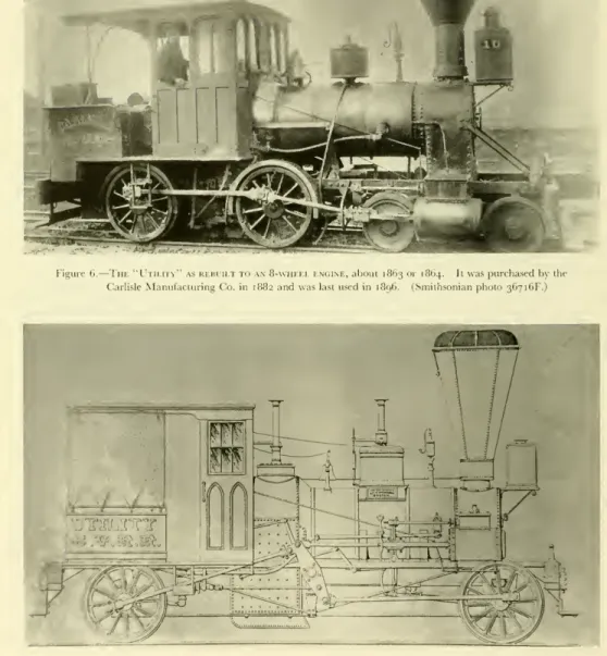
authorbelieves that the Railroad Advocate'sclaim ofSmith's designofthe Pioneerhasbeen confused with his designofthe Utility (figs.6, 7).Smith
designed thiscompensating-lever enginetohaultrainsovertheC.V.R.R.
bridge at Harrisburg. Itwas
builtby Wilmarth
in 1854.Accordingtostatementsof
Smith and
theBoard
ofManagers
quoted on page244, the Pioneerand
the Jenny Lind were notnew when
purchasedfrom
their maker, Seth Wilmarth.Although
of recentmanu-
facture, previoustoJune
1851, theywere
apparently doingserviceon
aroadinNorwich, Connecticut. It246
HIIIITIN 24<i:CONTRIBUTIONS FROM THE MUSEUM OF HISTORY AND TECHNOLOGY
C umberland \
/ai.u;vR
(umberland Valley
Ra ii Ro ad.
o\ THE FIRHT
i»*\ <»i ii.uim tillNEXT,
Ike
•-
IPASSENGER CARS
r i H iI -llail)a*follow*:
I.,,u, Ii„i„il„,,ln,,,l„l /...',O'clockIIItill I.,
arrivenl II.M ri-liinzal - al I «••-!•-1- ii 13 PbiladiIpliiabeforeIIP. >l
It,in, inn./ it »ill leaveHarrUunrg ion ,~ Ihe Cars from Philadelphia arrive,oboutjkn.,'./.../. in Ike iinnii: .milarrive.athamberaburgel '"•'*• */
(L/ ii bexpeeted lbalthia Train»ill in>simrt
linn l< .i. Philadelphia al*u inateadol tighto'clockin
tin- morning, and thenarrive atChamberabnrf; he/on
</iii7.oftin »; <l
j
There will '-• ' ulj line •!
mriGKT
CARS
fromthai .raborg to llarri. >g,whichwillran-} produce4 Herehandixetoand from Ihoac|il.i<•- inthe moat aafa, •hea| ' cxpetlil -
Prea'lCnmb.> Ii H I
«lh.1. v.I-:-.
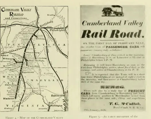
Figure4.
Map
01im Cumberland Valley
Railroadasii appearedinIigure ", \\1 \kiy briiadsidi hi"the
( umberlandValleyR.iilroad.
should be mentioned thaiboth Smith
and
Tylerwere formerlyassociatedwith theNorwich and
Worcester Railroadand
they probably learned of these two enginesthrough thisformerassociation. Itispossible that theengines were purchasedfromWilmarth
l>ythe(
umberland
Valley road,which had
bought several other Locomotives fromWilmarth
in previous years.It
was
the practiceofat leastoneotheiNew
England engine builder, theTaunton Locomotive
Works, to manufacture engines onthe speculation thata buyerwould
lie found: ifnoimmediate
buyers appeared the engine was leased to a local road until a sale was made.'•C. E. Fisiikk,"I.en111111iti\ !•-nltin-
New
11.urnRailroad,"Railwayand Locomoiiv, // Society Bulletin no. 46. p.48.
PAPER
42:THE "PIONEER*' OF
1851Regarding
the Jenny Lindand
Pioneer,Smith
re- ported7to theBoardofManagers
at their meetingofMarch
17. 1852:The
small tank engines which were purchased lasl .11 ...and whichIspokeinafi :rreport asunder- goingal thai time somi necessary improvements have since thai time beenfairly tested.istotheii capacity to run ourpassengei trainsandproved tol»-equal to thedim
.["he improvements proposed to be
made
have been completedonlyon one engine\JennyLind]whichisnow
running regularly with passenger trains the cosl ol repairsand improvements on thisengine(thisbeing the accidentally broken on the trial) amounted tolln-otherengineis now in thesimp,no readyfoi servicebulwillbea(anearlyday.
1Minutes C.V.R.R.
247
Figure6.
—
The
"Utility"asrebuiltto an8-\vheel engine,about 1863or 1864. Itwaspurchasedbythe CarlisleManufacturingCo.in1882and waslastusedin 1896. (Smithsonianphoto 36716F.)Figure7
hn
I 1n11 \."designedby SmithA.l'.andconstructedbySeihWilmarthin 1854, wasbuilt tnhaultrainsacross thebridgeatHamsburg,
Pa.248
Bl I IITIN 240:CONTRIBUTIONS FROM THE MUSEUM OF HISTORY AND TECHNOLOGY
i
l&titi&M
J«I 'J t**•
Figure8. Ini earliest
known
illustration ofthi / drawn by A.S.Hull,masta mechanicoftheCumberlandValley Railroadin187b. li depicts theengineasit appeared in1871. {Courtesy ojPaulWt>/.;The
Pioneerand
jenny hindachieved suchsuccess in.nlinn1l1.1tiln-presidentoithe road, FrederickWatts.
11urn1ic-ntedon1heirperformanceintheannualreport of the
Cumberland
Valley Railroadfor 1851. W.itts stated that since their passenger trains were rarelymore
than .1 baggagecarand
twocoaches, the light locomotives". . . have been found to be admirably adapted u>our business.''The Cumberland
Valley Railroad, therefore,added
twomore
locomotives oi similardesign in the nest few years. These engines were the Bostonand
the Enterprise, also built byWilmarth
in 1854-1855.Waits reported the Pioneei
and
Jenny hind cost J7,642.A
standard8-v\heelenginecostabout $6,500 to58,000 each duringthisperiod. In recent years, the Pennsylvania Railroad has stated the Pioneei cost|6 !00ingold,lnitisunaIiletogive thesourcefor tins information.
The
authorcandiscount thisstatement for it does notseem
reasonable that a linht. cheap engineofthe pattern of thePioi 1 couldcost asmuch
asa
machine
nearly twiceitssi/e.»EveningSentinel 1 arlisle,Pa Octobei 23,1901.
PAPER
42:THE "PIONEER"
OIISM
Service History
ol the PioneerAlter being put in service.thePioneei continued to perform well
and
was credited as ableto n car passenger train along smartly at Mlmph.
8 This tranquilitywas
shatteredin1 tctober1862 bya raiding party led by Confederate GeneralJ. E.B.Stuartwhich
CUMBERLAND^ 'RAIL ROAD.
NOT TRANSFERABLE.
until December 31si. 1863. unless otherwise ordered.
Figure 9.
Aw
\i pass ol the Cumberland Valley Railroadissm-d in 1863.24')
m m
w m H
isgjSsgs
P
— i
g <
fa
~ o
CO
o
"*Jsifpl I
*H'
i$
IEh »
S
£S
aj is >- Z
s;sg
'.1*
burned the
Chambersburg
sliopsoftheCumberland
ValleyRailroad.The
Pioneer,JennyLind,and
Utility were partially destroyed.The Cumberland
Valley Railroadinitsreport for 1862stated:The Wood-shop, Machine-shop, Black-smith-shop, Engine-house Wood-sheds, and Passenger Depol were totally consumed, and with the Engine-house three second-class Engines were
much
injuredti\ the Ere,but not so destroyed but that the) ma) l»- restoi usefulness.I \i'ii i.
—
Yearly
Mileage oftm
Pioniir<Annual Reports of theCumberlandVallev.Railroad) liar:
852.
853 854
W 3,182
'-Ml.~-'J
18,087 t-'
V
20,998
857 aa.779
858
29.57"
860 861.
862
864
868.
869.
870.
87..
872.
873 874 875 876.
877 878.
879 880.
I-;!''
5-339
-•-t 2,215 20, 46 5,709
I 626
1,372 102 002 721 466 636 87O 406 433 8.306
total •j(|--'~
'Mileage 1852 forJanuarj to September 1no record of mileage recordedinAnnua]Reportsprevious to11
b15,000 to20, I milesper yeai " 1-considered
mv
highmileageloralocomotiveofthe 1850's.
Nomileage reportedloranyenginesduetofit dNotlistedonroster.
Ilie Pennsylvania Railroad claims a total mileage of 255,675. This
may
be accountedfoi In records of n for1862, 1870,and1879.PAPER
42:THE "PIONEER" OF
1851However,
norecordcan be found of the extent or exactnatureof thedamage. The
shopsand
anumbei
o!'car-wen- burnedsoiiis reasonabletoassuur the call
and
otherwooden
parts "l the locomotive weredamaged.
<>ne unverified reportin thefilesof the Pennsylvania Railroad statesthatpartoftherooiand
brick wall fell <>n the Pioneei during the firecausing considerable
damage,
InJune
1864 the(
hambersburg
-hop- were again burned bj the< on- federates, buton this occasion the railroadmanaged
to
remove
all itslocomotivesbefore the raid. I1 the CivilWar,
theCumberland
Valley Railroad was obliged to operate longer passenger trains to satisfy theenlarged traffic.The
Pioneei and itssistei single- axle engineswere found too lightforthesetrainsand wen-usedonK
onwork
andspeiial trains. Reference to table 1 willshow
that the mileage of the /' felloff sharpl) forthe years I860 1865.In 1871 the Pioneei
was
remodeled by A. S. Hull, master mechanicof the railroad.The
exactnatureot the alterationscannot be determined,as no drawings orphotographsof theenginepreviousto thistimeareknown
to exist. Infact,thedrawing (fig.8)prepared by Hull in 1876to show theengineas remodeled in 1871 is the oldestknown
illustration of theP
Paul Westhaeffer, a lifelong student ofCumberland
Valley R.R.history, statesthataccordingtoan
inter- view with oneof Hull'sdestend,misthe only alterationmade
to the Pioneei during the 1871 "remodeling"was
the addition ofahandbrake.The
road'sannual report of1853describes thePioneei asasix-v.heeltank engine. Thereport of1854 mention-that thePioneer usedlinkmotion.These
statement-areenough
tognesubstancetothe idea thai the
bade arrangement
has survived unalteredand
thatitha- notbeenextensively rebuilt,a-wastheJennyLindin 1878.By
theKiln's.thePioneetwas
toolight for theheavier earsthen inuseand
by 1880ithad reached theend of its usefulness for regular service. Alter nearly thirty years on the road it had run 255,675 miles.Two
new passenger locomotives were purchased in 1880tohandlethe heaviertrains. In 1881 theP
wasdropped
fromtheroster,butwas
useduntilabout 1890forwork nun-
Alterthistimeitwas
stored in a shed at Falling Spring, Pennsylvania, near theChambersburg
yardsof theC.V.R.R.
Mechanical Description
ofthe Pioneer After the earl) I840's the single-axle locomotive, having one pairol driving wheels,was
largel) super-251
"Pioneer,"aboutigoi.sceneunknown.
Norrell.)
{PhotocourtesyofThomas
seeled
by
the 8-vvheel engine.The
desiretooperate longertrainsand
theneedforenginesofgreater trac- tiontoovercome
the steep gradesofAmerican
roads called for coupled driving wheelsand machines
of greaterweight thanthe4—2-0. After theintroduction of the 4 4 0, the single-axle engine received little attention in this country except forlight service or such special tasks asinspection ordummy
engines.There
was,however,arenewed
interest in ^singles''Figure 12. Iin "Pioneer"inCarlisle,Pa.,
1901. (PhotocourtesyojThomasNorrell.)
in the early 1850's becauseof \V. B.
Adams'
experi-ments
withlight passenger locomotivesin England.In1850
Adams
builtalightsingle-axletanklocomotive fortheEasternCountiesRailway which
proved very economicalfor lightpassengertraffic. Itwas
such a success thatconsiderable interest inlightlocomotiveswas
generated inthiscountryas well asin England.Nearly 100 single-axlelocomotives
were
built in the United States between about 1845-1870.These
engineswere
builtby nearly every well-known maker, from Hinkley in Boston to theVulcan Foundry
inSan
Francisco. DanforthCooke &
Co. ofPaterson builtastandard pattern4— 2—4 used bymany
roads.One
of these, the C. P. Huntington, survives to the present time.The
following paragraphsdescribe the mechanical detailsofthe Pioneer asitappears onexhibitioninthe Smithsonian Institution'snew Museum
of Historyand
Technology.The
boiler isthemost importantand
costly part of a steam locomotive, representing one-fourth to one- third of the total cost.A
poorly built or designed boilerwill produceapoor locomotiveno
matterhow
well
made
theremainderofmechanism. The
boiler of thePioneer isofthewagon-top, crownbar,fire-tube252
Bl I! ITIN 240:CONTRIBUTIONS FROM THE MUSEUM OF HISTORY AND TECHNOLOGY
style
and
ismade
of a '[(-inch thick, wrought-iron plate.The
barrel isvery small, in keeping withthe size oftheengine, beingonly 27 inches indiameter.While some
readersmay
believe this to be an ex- tremely earlyexample
of awagon-top
boiler,we
shouldremember
that mostNew England
builders produced few locomotives with the Bury (dome) boilerand that (liechiefadvocatesof this later style wen- the Philadelphia builders. By the early 1850'stin- I'.iiia boiler passed outof favor entirely
and
thewagon
topbecame
thestandard type of boilerwith.ill buildersin thiscountry.
Sixty-three iron tubes, I7,inches b) 85incheslong are used.
The
original tubesmay
have been copperor brass since these wereeasiei tokeeptighl thanthe lessmalleableiron tubes.
The
presenttubesheetisof ironbut was originall) copper. Its thicknesscannot beconveniently measured,but itisgreater than that oftheboilershell,probably aboul to inch.While
copper tubesand
tube sheets were notmuch
used in thiscountrya Iterabout 1870,copperwasemployed
as recently as 1950 by Robert Stephenson& Haw-
thorns, Ltd., on
some
small industrial locomotives.The
boilershellis lagged withwooden
tongue-and- groovestripsabout2%
incheswide(feltalsowas used for insulation during this period).The wooden
lagging is covered with Russia sheet iron which isheld inplace
and
thejointscovered bypolished brassAlba
F.Smith Alba
F.Smith,
theman
responsiblefor thepurchase
of the Pioneer,was born
inLebanon, Connecticut. June
28, 1817.''Smith showed promise
as amechanic
atan
earlyage and by
thetime bewas
22bad
establishedleadpipeworks
inNorwich.
His attentionwas drawn
particularly tolocomotives
since the tracks of theNorwich and Worcester Railroad
passed bis shop. Hisattempts
todevelop
a spark arrester for locomotivesbrought Smith
to the favorable attention ofCaptain Daniel Tyler (1799-1882),
president of theNorwich and Worcestei
Railroad.When Tyler was
hiredby
theCumberland
ValleyRailroad
in1850
tosupervise theline'srebuilding, bepersuaded
themanagers
of thatroad
to hireSmith
assuperintendent
ofmachinery.
1"Smith was appointed
assuperintendent
of themachine shop
of theCumberland Valley Railroad on July
22.1850." On January
1. 1851, hebecame
superintendent ol the road.»Norwich Bulletin(Norwich, Conn.), July24, IE data regarding A.F.Smithisfromthissource unless other-
\\isrnoted.
i"RailwayAge (September13.1889),vol. 14.no. ! Pagi
600 notes that Ijler worked on C.V.R.R. 1851-1852;
Smith'sdIiiiii.11\ foot e 9 mentions 1849.is the year;
and minutesofC.V.R.R. mention Tylerasearly as 1850
itMinutesC.V.RR
In
March
of1856 Smith
resigned hispositionwith
theCumberland
Valle)Railroad and became superintendent
of theHudson
Rivet- Railroad,where
heremained
foronly a year.During
that timehe designed
thecoal-burning locomotive
Irvington, rebuilttheWaterman con- densing dummy locomotive
for use in haulingtrams through
iit) streets,and developed
a superheater."After retiring
from
theHudson River
Rail-road he returned
toNorwich and became
active in enterprises in that area, including the presidency of theNorwich and Worcester
Railroad.While
the last years of Smith'slife
were devoted
to administrativework,
hefound time
formechanical
invention as well.In
1862
bepatented
a safety truck foi loco- motives,and became
president of aconcern which
controlled the-most important
patents forsuch
devices.'Alba
1".Smith
diedon July
21, 1879, inNorwich.
Connecticut.\ I Holley, [merican andEuropean Railu. iNew Y'.rk: 1861
An
illustrationofSmith's superheaterisshownmiplate58,figure13.
[ohnII White,"Introductionof theLocomoti
11ink." iPaper2i.1961,inContributionsfromthe \i
U.S National
Museum
Bulletin 22S:Washington: Smithsonian [restitutio p. 117.
PAPER
42:THE "PIONEER"
Ol- 1851253
•Sl <r3.'?1
01 WORKS
SOUTH BOSTON,
SETH WILMARTH, Proprietor,
193
STATIONARY STEAM ENGINES AND STEAM BOILERS,
OF THE
VARIOL'SSIZES REQUIRED,
Paris connectedwithRailroads,includingFrogs, Switches,Chairsand
Hand
Cars.MACHINISTS' TOOLS, ofalldescriptions,including
TURNING LATHES,
of sizesvarying from 6 feet to50feetinlength,and weighing from500 poundsto40tonseach; thelattercapableofturningawheelor pulley, thirty feetindiameter.
PLANING MACHINES,
Varyingfrom 2feetto 60feetinlength,and weighing from200lbs.to70tonseach,and will planeupto55feetlongand7feetsquare.
Boring
Mills, Verticaland Horizontal
Drills, SlottingMachines, Punch- ing Presses, Gear and Screw Cutting Machines, &c. &c.
Also,ittill
(Scaring ano Sljafting.
JOBBING AND REPAIRS, and any kind
ofwork usually done
inMa-
(jc-in
chine Shops, executed
atshort notice.254
Figure 13.
—
Advertisement of Seth VVilmarth appearing in Boston city directory for 1848-1849.
BULLETIN
240:CONTRIBUTIONS FROM THE MUSEUM OF HISTORY AND TECHNOLOGY
Figure14, Iin "Fury,"builtforthi Bostonand Worcestei Railroadini8.)<ibyWilmarth. li was known.isa"Shanghai"becauseofiisgreat height.
Smilhsiml.iii (11.111<•\ |iliuiiiI'lii'
Figure 15. Iin "Neptune," buili for nnj Boston and Worcester in 1847 '' s Hinkley and Drury.
Notethe similarity ol thisengineandthe Fury.
1igure Hi. Iin "Pioneer"as first exhibitedintheArtsand Industriesbuilding oi theSmithsonian Institutionprior to restorationof the sandbox. (Smithsonian photo 18069D
bands. Russia sheet ironisaplanish iron having .1 lustrous, metallicgrayfinish.
The
steam clonic (lie;. 18) islocated directK ovei the firebox, insidethe cab. It islaggedand
jacketed in anidenticalmanner
totheboiler.The
shellofthedome
isof ,r,-inchwrought
iron,the topcapisa cast-iron platewhichalso serves asa
manhole
coveroffering accesstotheboilcr"sinteriorlorinspectionand
repair.\round plan'._'0inchesindiameter,rivetedonthe forward endofthe boiler,just behind the bellstand, was found
when
the old jacketwas removed
inMay
1963. 1hevi/c.md shapeofthehole,
which
the platePAPER
42:THE "PIONEER"' OF
1851255
256 BULLETIN
240:CONTRIBUTIONS FROM THE MUSEUM OF HISTORY AND TECHNOLOGY
- -
—
X
-li
'- J =
3
b(-
x
=_
_ -^*> - ~ - >
" - s
Sags.
*
-:gog.
3
g£
8y
- ._
eg
i. - a
>
w
1 "'- c
&
- i - 5 r s - /
Si.—"en>
PAP]
R |2: IIII "PI<IN] l.R"OF
1851 224 r.27—
87 17257
covers, indicate that a steam
dome
ormanhole was
located at thispoint. Itispossible thatthiswas
the originallocation of thesteamdome
sincemany
build- ers inthe early 1850's preferred tomount
thedome
forward of the firebox. Thiswas done
in the belief that therewas
less danger of priming because the waterwas
less agitatedforward ofthe firebox.The
fireboxisasnarrow
as the boilershelland
fits easilybetween
the frame. It is a deepand narrow
box, measuring 27 inches by 28inchesby about 40 inchesdeep,and
iswell suited to burningwood. A
deepfirebox
was
necessary because a wide, shallowbox
suitableforcoalburning, allowedthefuel toburn
so quicklyitwas
difficulttofiretheengineeffectively.With
thedeep,narrow
firebox,wood was
filledup
to thelevelofthefiredoor. Inthisway,thefiredidnot burnso furiouslyand
did notkeepahead
ofthefire-man;
at thesame
time, since itburned
sofreely, agood
firewas
alwayson
hand.The
Pioneerburned
oakand
hickory.14 Forthe fireboxfi'6-inch thick sheetwas
used, forheaviersheetwould
haveblisteredand
flaked offbecause ofthe intenseheat ofthefireand
the fibrousquality ofwrought-ironsheet of the period.Sheet iron
was
fabricated frommany
small strips of iron rolled together while hot.These
strips were ideallywelded
intoahomogeneous
sheet,butinprac- ticeitwas
foundthe thicker the sheet thelesssure the weld.The
fire grates are cast ironand
set just a few inchesabove
thebottom
ofthewater spaceso that thewaterbelowthe gratesremainslessturbulentand mud
or other impurities in the water settle here.Four
bronzemud
plugsand
a blowoff cock are fitted to thebase ofthe firebox so that thesediment thus collectedcan beremoved
(figs. 17, 18).The
frontof the boilerisattachedtotheframeby
thesmokebox,which
isacylinder, boltedon alight, cast-iron saddle (not part of the cylinder castings nor attached tothem, but bolted directlyto thetop rail of the frame; itmay
be a hastilymade
repair puton
atthe shopsof the C.Y.R.R.).The
rear of the boilerisattachedto theframe bytwo
large cast- iron brackets,one on eachsideof the firebox(fig. 18).These
arebolted tothetoprail of theframe but the holesinthebrackets areundoubtedlyslotted,sothat theymay
slide since the boiler willexpand
about', inch
when
heated. In addition to thecrown
bars, which strengthen the
crown
sheet, the boiler is further strengthened by stay boltsand
bracesM AnnualReport,C.V.R.R., 1853.
located inthe
wagon
top overthe firebox,where
the boilerhad
beenweakened
bythe largehole necessary for the steamdome.
This boiler is a remarkably light,strong,and compact
structure.BOILER FITTINGS
Few
boilerfittings are found on the Pioneerand
itappears that little
was done
to update the engine withmore modern
devicesduring itsmany
years of service.With
the exception of the steam gauge, ithas
no more
boiler fitting thanwhen
it left the builder'sshopin 1851.The
throttlevalve isa simpleslidevalveand must
have been primitive for the time, for the balance- poppet throttle valvewas
in use in this country- previous to 1851. It is located directly below the steamdome
even though itwas common
practice to place the throttlevalve at the front of the boilerin the smokebox. Considering thecramped
condition inside the smokebox, therewould seem
to be littlespacefortheadditionofthe throttle valve: henceits present location.
The
dry pipeprojectsup
into the steamdome
togatherthehottest,drieststeamforthe cylinders.The
inverted, funnel-like capon
the top ofthedry pipeistoprevent priming,asdropsofwatermay
travelup
the sides of thepipeand
then to the cylinders,withthepossibilityofgreatdamage.
After the steamenters the throttlevalve itpasses through the frontend
of the valve, through the top of the boiler via the dry pipe (fig. 18), through the front tubesheet,and
thentothecylinders viathe petticoat pipes.The
throttle lever is a simplearrangement
readily understood from the drawings. It hasno
latchand
the throttle lever is held inany
desired setting bythewingnut and
quadrantshown
infigure 18.The
waterlevel inthe boilerisindicatedbythe three brasscockslocatedonthebackhead.Xo gauge
glassisused; theywere
notemployed
in thiscountry untilthe 1870's,although they werecommonly
used inEngland
atthetimethe Pioneerwas
built.While two
safety valveswere commonly
required, only onewas
used on thePioneer.The
safety valveis located
on
top of the steamdome.
Pressure isexertedonthe leverbya spring balance, fixed atthe forward endbya knife-blade bearing.
The
pressure can be adjusted bythethumbscrew
on the balance.The
graduated scaleon the balancegave a general but uncertainindication ofthe boiler pressure.The
valveitself isa poppet held against the face of the valveseat by a second knife blade attached to the258 BULLETIN
240:CONTRIBUTIONS FROM THE MUSEUM OF HISTORY AND TECHNOLOGY
lever.
The
ornamentalcolumn
forming thestand ol the safetyvalveiscast ironand
doesmuch
tode<orate the interiorofthecab. Ihepipecarryingtheescaping steam projects through the cab roof. It ismade
of copper with a decorative brass band. This entiremechanism
was replaced by amodern
saferj valve loruse atthe (Ihicago Railroad Fail (1949) Fortu- nately, the old valveu.i*preservedand hassin<ebeen replacedonthe engine.rhe
steam gauge
isa lateraddition, but couldhave been put on as early as the 1860's, since tin- most\<-<.Hi patent date that it bears is 1859. It is an
Ashcroftgauge havinga
handsome
-1 •! ()locomotive.edoniinsilver lace.
The
steam jet(item 3.Eg. 18)isone
ofthesimplest\ci most notable boiler fitting of the Pioneer, being nothing
more
thanavalvetappedintothe baseol the Steamdome
with a line running under the boiler jaikri tothesmokestack.When
the valve isopened
ajetofsteamgoes
up
thestack,creatingadraftuseful for starting the lire or enlivening u as necessary.This device
was
the invention ol Alba I . Smith in lo~>_'.accordingtotheeminent 19th-century technical writerand
engineerZerah
Colburn.18The two
feedwaterpumps
(fig. 20) arc loci ted be- neath thecab deck (I, fie;. 17).The)
are cast-iron constructionand
are driven by an eccentric on the driving-wheel axle (fig. 27).The
airchamber ordome
(1, fig. 27) imparts amore
stead)How
ol the water to the boilerby equalizing the surges ofwain
from the reciprocatingpump
plunger.A
steam line (3, fig. 18), which heats thepump
and prevents freezing in coldweather, is regulated by a valve in thecab
(figs. 18,27). .Votethat thelineonthe right sideofthecab has been disconnectedand
plugged.The
eccentric drive for thepumps
isunusual,and
the authorknows
ofno
otherAmerican
locomotive so equipped. l.astwickand
Harrison, it is true, favored an eccentric drivefor feedpumps.
Inn the)mounted
the eccentric onthe crankpin of the rear driving wheeland
thus produced in effect a half- strokepump.
Thiswas
notan unusual arrangement, thougha smallcrankwas
usuallyemployed
inplace ofthe eccentric.The
full-strokecrossheadpump
withwhich
the Jenny Lind (fig. 22) is equipped,was
of coursethemostcommon
styleofivv<.\pump
usedin thiscountryin the 19thcentury.()fallthe
mechanisms
ona19th-centurylocomotive,1 /irah CoLBURN,RecentPractice inLocomotio* Engines (1860), p.71.
Figure 19. Ba<
km
idof the Pioneer.(Smithsonian photo (.8069!
the feed
pump was
the most troublesome. Ifanengi- neer could think ofnothing else tocomplain about, he could usually call attention to a defectivepump
a\u\ not be found a liar. Because of this, injectors wen- adopted aftertheir introduction in I860. Itis
surprising that tin- /' • r, which vs.is in regular service as late as 1880
and
has been under streammany
times sincefornumerous
exhibitions,was
never fittedwithoneof these devices. Because itsvtn>k<- isPAPER
42:THE "PIONEER" OF
1851iy)
Seth Wihihivth
Littleis
known
of the builder of thePioneer,Seth Wilmarth, and nothing
in theway
ofa satisfactory history ofhis businessisavailable.For
the reader's generalinterest the followinginformation
isnoted.16Seth Wilmarth was born
in Brattleboro,Vermont, on September
8, 1810.He
isthought
tohave learned
themachinist
trade inPawtucket, Rhode
Island, beforecoming
to
Boston and working
for theBoston Loco- motive Works, Hinkley and Drury
proprietors.In about 1836 he opened
amachine shop and, encouraged by an expanding
business, in 1841he
builtanew shop
inSouth Boston which became known
as theUnion Works.
17Wilmarth was
inthe generalmachine
businessbut
hisreputationwas made
in themanufac-
ture ofmachine
tools,notably
lathes.He
isbelieved to
have
built his firstlocomotive
in 1842,but locomotive
buildingnever
be-came
hismain
line ofwork. Wilmarth patterned
his engines after those ofHinkley and undoubtedly,
incommon with
the otherNew England
builders ofthisperiod,favored
the steady-riding, inside-connection engines.The "Shanghais,"
so-calledbecause
oftheir great height, built fortheBoston and Worces-
terRailroad by Wilmarth
in1849,were among
the best
known
inside-connection engines'RailroadGazelle(Septembei 27,1907),vol.43, no. 13, pp.357-360. ThesenotesonWilmarth locomotives byC.
II.(larutherswereprintedwithseveral errorsconcerningthe locomotives of theCumberlandValleyRailroadand prompt- edthe preparation of these present remarksonthe histor)
ill
U
illii.iiih'sacthLties. Notethaton page 359itisreportedthat mils one compensating-lever engine wasbuiltforthe C.Y.K.K inll!")l..milnottwo suchenginesin18.' ["hi
i incorrectly identified as a "Shanghai." and as beingoneof liner such enginesbuiltin1871by Wilmarth.
>: the authorisindebtedtoThomasNorrellfortheseand
many
of the otherfactsrelating toWilmarth'sUnionWorks.operated
in thiscountry
(fig. 14).While
the greater part ofWilmarth's
engineswas
built forNew England
roads,many were con-
structed for linesoutside that area,including
thePennsylvania
Railroad,Ohio and Penn-
sylvania Railroad,and
the Erie.A comparison
of the surviving illustrations ofHinkley and Wilmarth
engines of the 1850's revealsaremarkable
similarityin their details (figs. 14and
15).Notice
particularly the straightboiler,rivetedframe, closelysettruck wheels,feed-water pump driven by
a pinon
thecrank
of the driving wheel,and
details of thedome
cover. All of the features areduplicated
exactlyby both
builders.This
is not surprising considering the
proximity
ofthe plantsand
thefactthatWilmarth had been
previouslyemployed by Hinkley.
In
1854 Wilmarth was engaged by
theNew
York and
ErieRailroad
to build fifty6-footgauge
engines.1S Afterwork had been
startedon
theseengines,and
a largestoreofmaterialhad been purchased
for their construction,Wilmarth was informed
thatthe railroadcould
notpay cash but
thathe would have
to take notes inpayment.
19There was
at thistime
amild economic panic and
notescould be
soldonly
at aheavy
discount.This
crisis closedtheUnion Works. The next
year, 1855,Seth Wilmarth was appointed master me- chanic
oftheCharlestown Navy Yard,
Boston,where he worked
fortwenty
years.He
died inMaiden, Massachusetts, on November
5, 1886.isRailroadGazette(October 1907),vol.43,p.382.
is BostonDaily Evening Telegraph(Boston, Mass.),August 11. 1854. Thearticlestated that one engine aweek was built and that 10engineswere alreadycompleted forthe Erie. Construction had startedon 30others.
260 BULLETIN
240:CONTRIBUTIONS FROM THE MUSEUM OF HISTORY AND TECHNOLOGY
Figure 20. Feedwateb pump ol the Pioneer. (Smithsonian ph
sliort and the plunger is in less rapid motion, the present eccentric arrangement is
more complex
butless prone to disorder than the simpler but Faster crosshead
pump.
The
check valves are placed slightly below the centerline of the boiler (fig. 18).These
valves are an unfinished bronzecastingand
appear to be ofa hicut pattern,probably dating fromthe 1901renova- tion. At thetimetheenginewas
built, itwas
usual to house thesevalves in an 0rn.m1ent.1l spun-brass1In- smokestackisof the bonnet type
com- monly
used onwood-burning
locomotives in this country between about 1845and
187(1.The
exhaust steam from the cylinders isdirectedup
the straight stack(showninphantom
infig.27)bythe blast pipe.Thiscreatesa partial
vacuum
in thesmokebox
th.itdraws the fire, gases, ash,
and smoke
through the boiler tubes from the firebox. 1he force of the exhaustingsteam blowsthem
out thestack. At the topofthe straight stackisa deflectingconewhich
slows the velocity of the exhaustand
changes itsdirection causing it to godown
into the funnel-shaped outei casing of the stack. Here, the heavyembers and PAPER
42:THE
'T'lONKI-.R" 1>FISM
cinders are collected
and
preventedfrom
directly discharging into tin- countryside as dangerous fire- brands.Wire
netting is stretched overtop of the deflecting cone to catch the lighter,more
volatileembers which may
defy the action of the cone.The
term "bonnetstack" resultsfrom
thefactthatthis netting issimilar inshape toa lady's bonnet.The
cinders thusaccumulated inthe stack'shopper could beemptied by
opening
a pluu.it 1he baseofthe stack.While
the deflecting conewas
regarded highly as a sp.nk.in esterand
usedpracticallytothe exclusion other arrangement, ithad
the basic defect ol keepingthesmoke
lowand
closetothetrain. Thiswas
.1great nuisancetopassengers, asthelow trailingsmoke
blew into the ears. If the exhausthad
been allowed to blast straight out the stack high into the air. most i«liIk'sp.nkswould
have burned outbefore touchingtheground.IR\M1
The
frameofthePioi exactclassification butitmore
closelyresemblesthe riveted- orsandwich-261
Figure21 .
—
"Pioneer"onexhibitinoldArtsandIndustriesbuildingofthe SmithsonianInsti- tution. Inthisviewcan be seenthebonnetscreenof thestackand arrangementofthe boiler- frame bracesand otherdetails not visiblefromthe floor. (Smithsonian photo 48069A.)
Figure22.
—
"Jennyi.ind,"sisterengine of the Pioneer,shownhereas rebuilt in1878foruse asaninspectionengine. Iiwasscrappedin
March
1905. (Photocourti>iq)E. P. Alexander.)262 BULLETIN
240:CONTRIBUTIONS FROM THE MUSEUM OF HISTORY AND TECHNOLOGY
Figure 23.-
Cyundi
r head with valve b<>\removed.
Figure 24.
—
Bottom ol valve box with sli<l<-
valveremoved.
25and 26.
—
Cylindirwith valve boxremoved, >tn\ \i11_;val
typeframe than
any
other (I'm-. 18,27).While
the simple bar frame enjoyed the greatest popularityin the last century, riveted frames were widely used in this country, particularly by the .NewEngland
buildersbetween aboutWHO and
WitiO.The
riveted framewas
fabricated from two platesofiron, about%-inch thick,cuttotheshapeofthetoprail
and
the pedestal.A
bar about 2 inches squarewas
riveted between the two plates.A
careful study of photo- graphs of Hinkleyand
otherNew
England-built engines of theperiodwillrevealthis styleofconstruc- tion. The frame<>)'the Pioneer differsfrom theusual rivetedframeinthat the toprailis1s
4inches thick by IV inches
deep and
runsthe length of thelocomotive.The
pedestals aremade
oftwo
3s-inch plates flush-riveted to each side ofthe top rail.
The
cast-iron shoeswhichserve asguidesforthejournal boxesalso act as spacersbetween thepedestalplates.The bottom
railof theframeisa l' s-inclidiameter rodwhich isforgedsquareatthe pedestalsand
forms the pedestal cap.The
frame is further stiffened by two diagonalrodsrunningfrorn thetup ofeachtruck- wheel pedestal to the base of the driving-wheel pedestal, forming a truss. Six rods, riveted to the boiler shelland
bolted to the frame's top rail,strengthentheframelaterally. Fourofthese rod-.an beseen easily as theyrun fromtheframetothemiddle ofthe boiler; the othertwoare rivetedtotheunderside of the boiler.
The
attachment of these rods to the boilerwas
an undesirablepractice,forthe boilershellPAPER
42:THE "PIONEER" OF
1851263
was
thus subjected to theadditional strain of thelo- comotive'svibrations asitpassedoverthe road. In lateryears, aslocomotivesgrew
in size, thispracticewas
avoidedand
frameswere made
sufficientlystrong tohold the engine'smachinery
in linewithout using the boilershell.The
frontand
rearframebeams
are offlat iron plateboltedtotheframe.The
rearbeam had
been pushed in during an accident,and
instead of itsbeingreplaced,anotherplate
was
rivetedon and
bent outintheopposite direction toform
apocketforthe rearcouplingpin.Note
thatthereisno drawbar and
thatthecouplerismerelyboltedtothebeams. Since theengine only pulled lighttrains, thearrangement was
sufficientlystrong.RUNNING GEAR
The
running gearissimplysprung withindividual leaf springs for each axle; it is not connectedby
equalizing levers.To
find anAmerican
locomotive not equipped with equalizersis surprising sincethey were almost a necessity to produce a reasonablysmooth
ride on therough tracks ofAmerican
rail- roads. Equalizers steadied themotion
oftheengine bydistributingtheshockreceivedby any
one wheel or axle toalltheotherwheelsand
axles soconnected, thus minimizing the effects of anuneven
roadbed.The
authorbelieves that the Pioneeris ahard-riding engine.The
springs of themain
drivesaremounted
in the usual fashion.The
rear boiler bracket (fig. 18) is slotted sothat the spring hangermay
pass through foritsconnection withtheframe.The
spring of the leadingwheelsissetat rightangles to theframe(fig.27)
and
bears on abeam,
fabricated of iron plate,which
inturn bearsonthejournalboxes.The
springs of the trailingwheels aresetparallel with theframeand
aremounted
betweenthepedestal plates(fig. 18).The
center of the drivingwheeliscast ironand
has spokes ofthe old rib pattern,which
is aT
in cross section,and was
used previoustotheadoptionofthe hollow spoke wheel. Inthemid-1830'sBaldwin and
othersusedthisrib-patternstyleofwheel, exceptthat the rib faced inside.The
present driving-wheel centersareunquestionablyoriginal.The
sisterengine JennyLind(fig.22)was
equipped withidenticaldriving wheels.The
presenttiresare verythinand beyond
theirlastturning.They
arewrought
ironand
shrunk to fit the wheel centers. Flush rivets are used for further security.The
leftwheel,shown
infigure17,iscrackedatthe
hub and
isfitted withan
iron ring topreventitsbreaking.The
truck wheels, of thehollow spokepattern,are cast iron with chilled treads.They were made
byAsa
Whitney, oneoftheleadingcar-wheelmanufac-
turer^in thiscountry,whose
extensive plantwas
located in Philadelphia.Made under
Whitney's patent of 1866, thesewheelsmay
well have beenadded
tothe Pioneer duringthe 1871 rebuilding. Railroad wheelswere
notcastfrom
ordinarycastiron,which was
tooweak and
brittle tostandthe severe service forwhich
theywere
intended,but from ahigh-quality cast iron similartothatusedforcannons. Itstensilestrength,which
rangedfrom
31,000to36,000psi,was
remark- ably highand
very nearlyapproached
that of the bestwrought-ironplate.The
cylinders are cast iron withan
8,^-inch bore about half the size of the cylinders of a standard 8-wheel engine.The
cylinders are bolted to the frame but not to the saddle,and
are set at a 9°angle to clear the leading wheels
and
at thesame
timetolineup
with the center of thedriving-wheel axle.The wood
laggingiscoveredwith adecorative brass jacket.Ornamental
brass jacketingwas
ex- tensively used on mid- 19th-centuryAmerican
loco- motives to cover not only the cylinders but steamand
sand boxes,checkvalves,and
valveboxes.The
greater expense for brass (Russia iron or painted sheet iron
were
acheapersubstitute)was
justifiedby
theargument
that brass lasted thelifeof the engine,and
couldbe reclaimedforscrapatapriceapproach- ing the original cost;and
also thatwhen
brightly polished it reflected the heat, preventing lossby
radiation,and
its bright surface could be seen a great distance, thus helping to prevent accidents at grade crossings.The
reader should be careful not to misconstruetheabove arguments simplyas ration- alization on the part of master mechanicsmore
intenton
highly decorative machines than on the practical considerations involved.The
valve box, a separate casting, is fastened to the cylinder castingby
six bolts.The
side cover plateswhen removed show
only a small opening suitablefor inspectionand
adjustment ofthe valve.The
valvebox must
beremoved
topermit repairoi removalofthe valve.A
betterunderstandingofthismechanism and
thelayoutofthe partscan be gainedfrom
astudyof figures 23-26, 28 (8, 8a,and
8b).Both crossheads
were
originally of cast iron but oneofthesehasbeen replacedand
isofsteel.They
run intosteel guides, bolted at the forwardend
to264 BULLETIN
240:CONTRIBUTIONS FROM THE MUSEUM OF HISTORY AND TECHNOLOGY
V
.
15 _
"
C.i
§
*
-— -C
1%
PAPER
42:THE "PIONEER" OF
1851224 •"•JT ilT l
1 -
265
'
1igure .'ii. -'"Pionklr" on exhibit in old Artsand Industries building,showing the tankand backhead.
Smithsonian photo 18069]
conductor to signal the engineer is fastened to the undersideof thecabroof. Thisstyleof
gong was
in useinthe 1850'sand may
wellbeoriginalequipment.The
water tankisintwosections,onepartextending below thedeck,between theframe. The tankholds 600gallons ofwater.The
tender holdsone cord ofwood.
The
smallpedestal-mounted sandboxwas
usedon severalCumberland
Valley engines including the/' !. This
box was removed from
theenginesome- timebetween 1901and
1904. Itwas
ontheengineat the time of the Carlisle sesquicentenniaJ but dis- appeared by the time of the St. Louis exposition.lwo
smallsandboxes,mounted
onthedriving-wheel splash guar