Our deep sense of gratitude to Ms. Itishree Mishra, M.Tech (Res), Department of Civil Engineering, National Institute of Technology, Rourkela, for her support and guidance. Study of variation of natural frequency with changing number of floors and fixed number of bays. Study of variation of natural frequency with changing number of bays and fixed number of floors.
This project is concerned with the two-dimensional analysis of a plane frame under arbitrary ground motion and loading conditions. The variation of static properties and dynamic properties with different numbers of stories and bays in the frame element has been investigated. The numerical analysis was experimentally verified by determining the natural frequency of the airframe model using an FFT analyzer.
The concept of the finite element method is used for numerical analysis where the model in question is divided into components called finite elements and the response of each element is expressed in terms of a limited number of degrees of freedom characterized as the value of an unknown function. .
LITERATURE REVIEW
Reference to the recent and current technical literature shows that the problem of the dynamics of building frames is a topic of great importance mainly because there is a need for practical and accurate techniques to be used in the design of such structures. 1] Thus is the importance of dynamic and static analysis of frame structures under different conditions. 2] We have studied the various properties of a plane frame element and developed a MATLAB code for two-dimensional numerical analysis of a plane frame.
The analyzes performed were done under the assumption that the connecting joints are completely rigid. Shousuke Moring and Yasuhiro Uchida, in their paper "Dynamic response of steel frames under earthquake excitation in horizontal arbitrary direction", conducted a dynamic analysis of the elasto-plastic response of single-story single-story space frames. It is shown that the displacement responses under the bidirectional excitation are larger than those under the unidirectional excitation, leading to an earlier collapse in the earlier case.[4]
Chapter 2 discusses the various attributes of the numerical analysis, matrices involved in the calculations for static analysis, formulation of the stiffness matrix and the system of
PLANE FRAME ELEMENT
- FORMULATION OF SYSTEM OF EQUATIONS
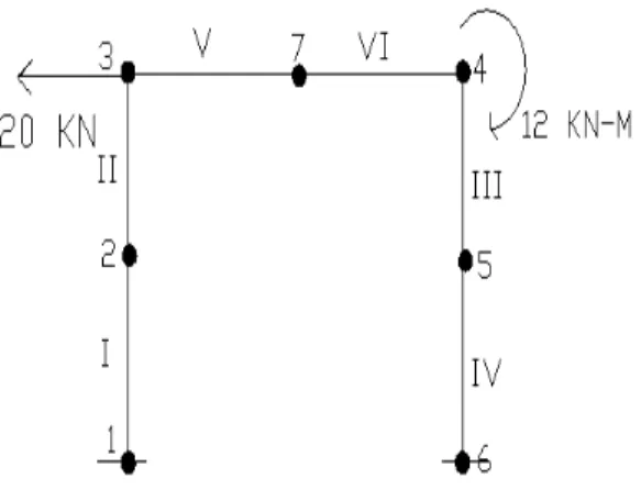
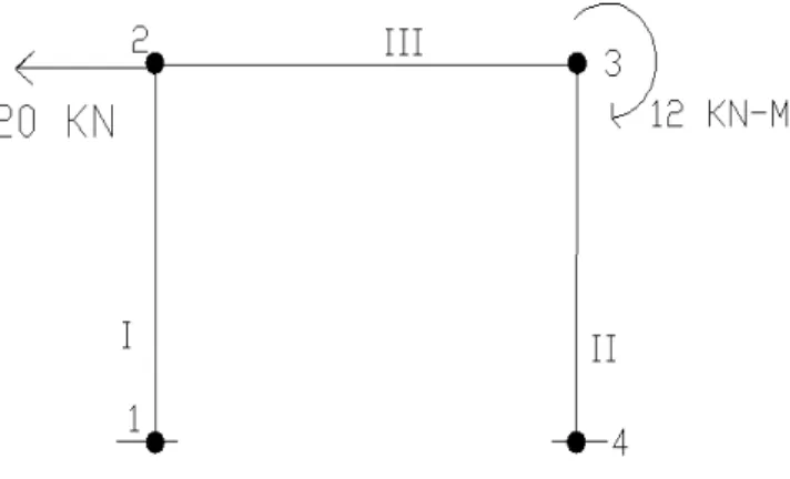
In the case of a plane frame, all the elements lie in the same plane and are connected by rigid joints. The internal stress results at a cross section of a planar frame member consist of bending moment, shear force and an axial force. The planar frame element has modulus of elasticity E, moment of inertia I, cross-sectional area A and length L.
Each plane frame element has two nodes and is inclined by an angle θ measured counterclockwise from the global positive X axis. A plane frame element has six degrees of freedom: three at each node (two displacement and a rotation). Where {f} is the 6X1 nodal force vector in the element and u is the 6X1 element displacement vector.
Dynamic analysis of plane frame elements includes axial effects in the stiffness and mass matrices.
MASS MATRIX
- MASS MATRIX PROPERTIES
It also requires a coordinate transformation of the nodal coordinates from element or local coordinates to system or global coordinates so that appropriate superposition can be used to assemble the system matrices. A computer program in the form of MATLAB code has been developed for both static and dynamic analysis of plane frames. The master mass matrix is built up from element contributions, and we start at that level.
The construction of the mass matrix of individual elements can be carried out in several ways. These can be divided into three groups: direct mass clumping, variable mass clumping and template mass clumping. In direct mass clumping, the total mass of element e is directly assigned to the nodal freedoms and a diagonally merged mass matrix is formed.
An important motivation for direct lumping is that a diagonal mass matrix can provide computational and storage advantages in certain simulations, especially explicit time integration. In variational mass lumping, a second class of mass matrix construction methods is based on a variational formulation. Mass arrays must meet certain conditions that can be used for verification and debugging, namely the following.
Conservation: At least the total mass of the element must be conserved, which can be verified by using a uniform translational velocity and checking that the linear momentum is conserved. It can be checked in two ways: via the Me eigenvalues or the sequence of major minors. A general problem in free vibrations is the evaluation of the eigenvalue λ, which is a measure of the frequency of vibration together with the corresponding eigenvector U, which shows the mode shape as v KU = λM.
For a positive definite symmetric stiffness matrix of size n, there are n real eigenvalues and corresponding eigenvectors that satisfy the above equation. The eigenvectors have the property of being orthogonal with respect to the stiffness and mass matrix.
MODE SHAPES
The length of an Eigen vector can be determined by setting its largest component to a preset value, such as unity. The main mathematical advantage of determining mode shapes is that they will be orthogonal to each other. For design engineers, mode shapes are useful because they represent the shape in which the building will vibrate in free motion.
By understanding the vibration modes, we can better design the building to withstand earthquakes.
FREE VIBRATION: DAMPED AND UNDAMPED SYSTEMS
The Eigenvalue problem is solved for natural frequencies and modes and a general solution to the above equation is given by superposition of the response in individual modes, given by: u(t)= Φn (An cos ωnt +Bn sin ωnt). For systems with damping, the free vibration response of the system is determined by p(t)=0: mü + ců+ ku = 0.
DYNAMIC ANALYSIS BY NUMERICAL INTEGRATION
- SOLUTION TO EQUATION BY NUMERICAL INTEGRATION The Numerical Solution can be calculated by various methods
- Newmark Integration Method The steps involved are
INITIAL CALCULATION
- STEPS INVOLVED IN 2-D FRAME ANALYSIS
- EXPERIMENTAL ANALYSIS: FFT ANALYSER
- STATIC ANALYSIS
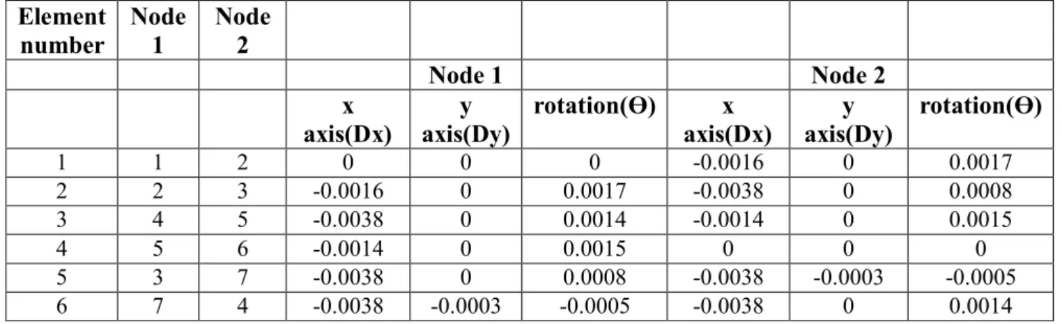
The code, written in MATLAB, determines the nodal displacements, forces, and end moments at various nodes in the beam and column element of the plane frame as part of the static analysis. Calculation of the local stiffness and mass matrix for each frame element using the plane frame element stiffness and the plane frame element mass function. Composing the local stiffness matrix into a global stiffness and mass matrix using the frame 1 compositing planar function.
Mapping the axial force, shear force and bending moment at each node with respect to the length using functions such as the plane frame member shear force, the axial force and the bending moment diagram. The static and dynamic response of a planar frame under varying loads and boundary conditions has been obtained and tabulated and its implications studied. This section deals with the static analysis of the plane frame and the determination of the nodal displacements and forces for a given lateral load through finite element programming using a MATLAB code.
For the first problem, we consider a one-story building and by changing the number of nodes in the columns and beams we compare the results obtained at each node. Total number of intermediate nodes in each column= 0 Total number of intermediate nodes in each beam= 0 Number of stories= 1. Total number of nodes in the planar frame=4 Total number of elements in the planar frame=3.
Total number of nodes in each column = 1 Total number of nodes in each beam = 1 Number of floors = 1. Total number of nodes in a plane frame = 7 Total number of elements in a plane frame = 6. As the system progresses, increasing the number of nodes helps to increase the accuracy and the accuracy of the results obtained.[5]
We obtain the values of deflection in x and y directions and rotations at the point of force application and the values of base moments by varying the number of floors with the number of bays fixed as 1. The results obtained are as follows- Table 6.6 Deflection results for varying number of floors. It is seen that deflection at both x, y axis and rotation increases with increase in number of floors. This is due to the reason that the stiffness matrix K of the plane frame decreases with increase in number of floors since K is inversely proportional to length of frame.
VARIATION OF FOUNDATION MOMENTS WITH DIFFERENT NUMBER OF FLOORS WITH SINGLE BACK FLOOR WITH SINGLE BACK.
Moment in z direction(KNm)
VARIATION OF BASE MOMENTS WITH DIFFERENT NUMBER OF BAYS AND FIXED NUMBER OF STOREYS
As the area increases, the base moment is spread over a larger area and hence the decreasing pattern.
Base Moment in Z direction
- COMPARISON OF EXPERIMENTAL AND NUMERICAL ANALYSIS RESULTS
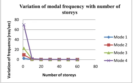
- STUDY OF VARIATION OF NATURAL FREQUENCY WITH CHANGING NUMBER OF STOREYS AND FIXED NUMBER OF BAY
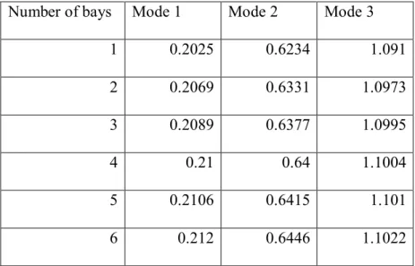
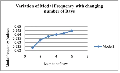
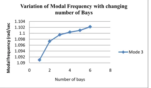
- STUDY OF VARIATION OF NATURAL FREQUENCY WITH CHANGING NUMBER OF BAYS AND FIXED NUMBER OF STOREYS
- INFERENCE
- DYNAMICS ANALYSIS UNDER DIFFERENT LOAD CONDITIONS 1. SYSTEMS WITHOUT DAMPING
- Arbitrary Load on Ground
- Arbitrary Load on Ground (a) ELCENTRO DATA
The MATLAB code is executed for different floors and different bays of buildings for dynamic analysis of the frame structure. The free vibration frequency is calculated at each node and the forced vibration analysis is done under different load conditions. STUDY OF VARIATION OF NATURAL FREQUENCY WITH CHANGING NUMBER OF FLOORS AND FIXED NUMBER OF BAY NUMBER OF FLOOR AND FIXED NUMBER OF BAY.
As the number of stories increases, the length of the frame element increases and thus the stiffness [K], as it is inversely proportional to the length. This is because the frequency of the earthquake does not correspond to the natural building frequency. INVESTIGATION OF THE VARIATION OF NATURAL FREQUENCY WITH CHANGING NUMBER OF BAYS AND FIXED NUMBER OF FLOORS NUMBER OF BABIES AND FIXED NUMBER OF FLOORS.
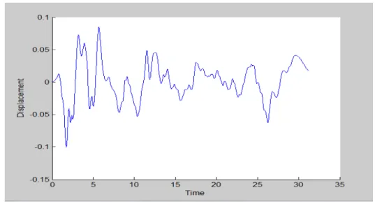
Therefore, by increasing the number of bays, an increasing pattern is observed in the modal frequencies. The Elcentro data is the data of the earthquake that occurred in Elcentro during May 18, 1940. Total number of intermediate joints in each column= 1 Total number of intermediate joints in each beam = 1 Number of floors= 20.
Total number of nodes in the plan frame=102 Total number of elements in the plan frame=120. The maximum earthquake force acting in the IS code data is 1N and the maximum displacement we obtain is 0.06m. Under forced vibration mode, the nature of the graph changes as the nature of the load changes.
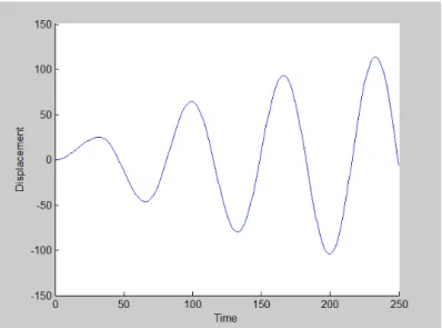
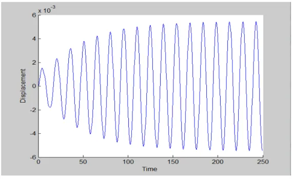
The resonance graph is obtained when the forced oscillation frequency matches the natural oscillation frequency of the frame element, at which the maximum displacement is achieved. In the damped condition, the damping factor C is introduced in the forced vibration analysis of the same multistory and multispan frame. The obtained result is the dynamic and static properties of two-dimensional frame structures, such as the natural frequency of the structure, shear force, bending moment in any floor of the frame structure.
It was seen that when the forced vibration frequency matches the natural frequency of the structure, resonance peak occurs.