In this work, a hybrid controller has been developed to improve the performance of a cage induction generator used for wind power applications. The wind power generation system uses an indirect vector controlled cage induction machine as a generator.
WIND TURBINE SYSTEM
POWER CONTAINED IN WIND
TYPES OF WIND CONVERSION DEVICES
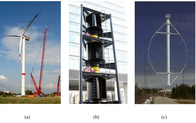
WORKING OF MODERN WIND TURBINES
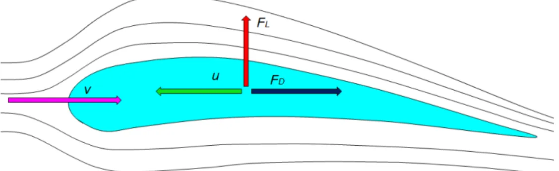
- The Darrieus rotor
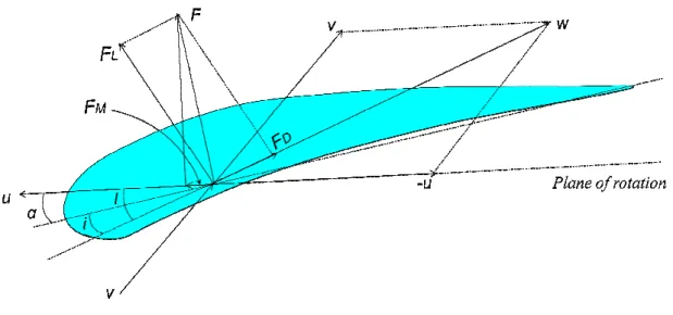
The magnitude of these two forces will be proportional to the square of the relative wind speed. The relative wind is given by the vector sum of the wind speed and the negative of the airfoil speed since it will now be perpendicular to the relative wind, the drag will be parallel to it.
IMPORTANT TERMS RELATED TO WIND POWER GENERATION .1 Solidity
- Tip Speed Ratio (TSR)
- Power coefficient (C p )
- Specific Rated Capacity (SRC)
The tip speed ratio of a wind turbine is defined as the ratio of the speed of the rotating blade tip to the speed of the free stream wind. On the other hand, low solidity rotors have low torque and high speeds and are. the ratio of the speed of the rotating knife tip to. is the rotational speed in is the wind speed without rotor interruption in m/sec.
WIND TURBINE CHARACTERISTICS
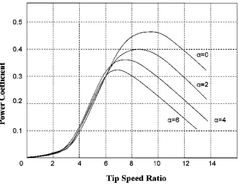
- Power Coefficient versus Tip Speed Rat The graph of the power coefficient (C
- Power versus Speed Characteristics The wind turbine power curves shown in Figure 1
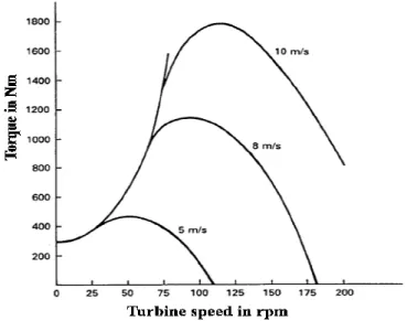
- Torque versus Speed Characteristics
Since the same wind turbine can produce widely varying amounts of wind speed, the SR g. For a given turbine, the power coefficient depends not only on the TSR, but also on the blade pitch angle (α).
WIND TURBINE CONTROL SYSTEMS
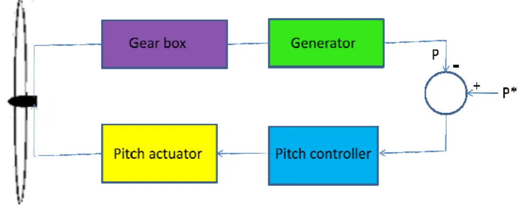
- Pitch Angle Control In this type of control
- Stall Control
The generator must be used in such a way that the mechanical output of the turbine is optimally used at the rated wind speed. As wind speed changes, the pitch angle control system aligns the blade in the direction of the relative wind, moving the blade.
WIND POWER CONVERSION SYSTEMS
FIXED SPEED WIND TURBINE
In a fixed speed wind turbine, the induction generator is directly connected to the power grid according to Figure 1.15. The rotor speed of a fixed speed wind turbine is in principle determined by the gearbox and the number of pole pairs of the generator.
VARIABLE SPEED WIND TURBINE
The gearbox is designed in such a way that the maximum rotor speed corresponds to the rated speed of the generator. Synchronous generators or permanent magnet synchronous generators can be designed with multiple poles, implying that no gearbox is required.
GENERATORS FOR WIND POWER APPLICATIONS
SQUIRREL CAGE INDUCTION MACHINE
WOUND ROTOR INDUCTION MACHINE
PERMANENT MAGNET SYNCHRONOUS MACHINE
SELF EXCITED AND LINE EXCITED INDUCTION GENERATORS
SELF EXCITED INDUCTION GENERATORS
LINE EXCITED INDUCTION GENERATORS
Due to the fact that the induction generator absorbs the reactive power on the generation side poor power factor.
CONTROL OF LINE EXCITED
LINE EXCITED CAGE INDUCTION GENERATORS
INDUCTION GENERATORS
MOTIVATION
It is also evident from the recent scenario that wind energy is generating a lot of interest in the power generation sector. If wind energy could be efficiently captured, it could solve problems such as environmental pollution and the unavailability of fossil fuels in the future.
OBJECTIVES
Generation of pollution-free power has become the main goal for researchers in electricity production. Development and implementation of new controllers to improve the transient and steady state performance of the line-excited induction generator system.
ORGANISATION OF THE THESIS
The control of the grid-side converter is done to improve the power factor of the wind power generation system. Chapter 6 contains the details of the manufacturing of the control circuit for controlling a PWM converter-inverter set.
Q Modeling And Vector Control of Induction Generator
- INTRODUCTION
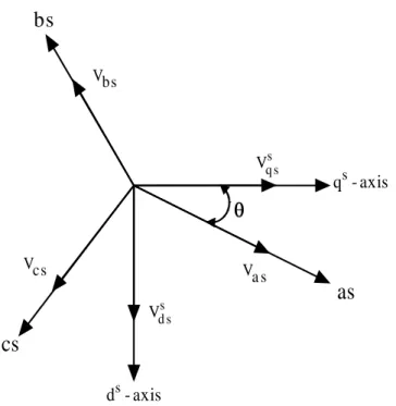
- AXES TRANSFORMATION
- D-Q MODEL OF INDUCTION MACHINE (KRON’S EQUATION)
- VECTOR OR FIELD ORIENTED CONTROL
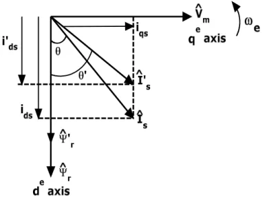
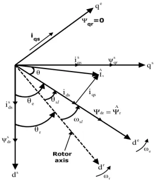
- EQUIVALENT CIRCUIT AND PHASOR DIAGRAM Consider the d e − q e
- PRINCIPLE OF VECTOR CONTROL
- CONCLUSION
Assuming that the ds-qs axes are oriented at an angle θ as shown in Figure 2.1, the voltages vdss. The basics of vector control implementation can be explained with the help of figure 2.10, where the machine model is presented in a synchronously rotating reference frame.
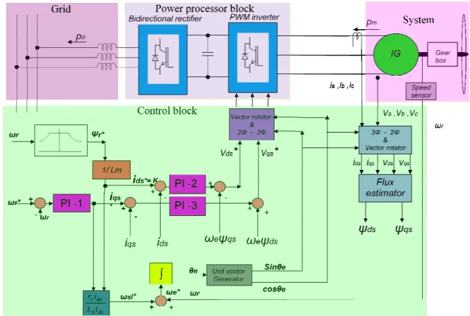
Indirect vector control of cage induction generator
- INTRODUCTION
- INDIRECT VECTOR CONTROL OF INDUCTION GENERATOR
- SIMULATION RESULTS AND DISCUSSION
- STEP CHANGE IN TURBINE TORQUE
- STEP CHANGE IN REFERENCE SPEED COMMAND
- CONCLUSION
The electromagnetic torque response of an induction generator with PI controllers is shown in Figure 3.3. Figure 3.3 shows that it is a 4% overshoot, which is within the permitted range. From Figure 3.6, it can be seen that due to the change in turbine torque, the quadrature axis current or torque component of the current changes, while the flux component or direct current almost remains unchanged, which is due to the effect of the vector control strategy.
The power factor response is given in Figure 3.7, which shows that as the turbine torque changes from 10 Nm to 15 Nm, the power factor increases from 0.342 to 0.42. The performance of the propulsion system is re-evaluated by subjecting the system to a step change in the reference speed. Figure 3.12 shows the current response of the machine on the direct and quadrature axes when a reference speed change command is given.
Performance improvement of field oriented induction generator using modern controllers
INTRODUCTION
FUZZY CONTROLLER
- INTRODUCTION
- FUZZY SETS
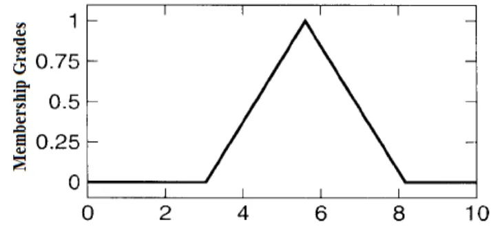
- MEMBERSHIP FUNCTIONS
- Triangular Membership Functions
- Trapezoidal Membership Functions
- Generalized bell Membership Functions
- Sigmoidal Membership Functions A sigmoidal membership function is defined by
- Defuzzification Methods
- DESIGN OF FUZZY LOGIC
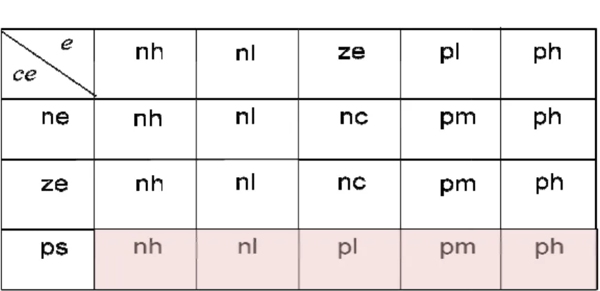
- Knowledge Base and Inferencing
The basic structure of the fuzzy logic controller is given in the fuzzy logic controller is the normalized error values. The basic structure of the fuzzy logic controller is given in figure 4.7, where the inputs to the fuzzy logic controller are the normalized error values 'e' and. Normalization is done to limit the universe of input discourse between .. the controller can be successfully operated within a wide range of input variations.. are the normalization factors for error input and error input variation respectively.
The output of the fuzzy logic controller is then multiplied by a gain 'Ko' to obtain the appropriate control. The output gain is also taken as a constant for this fuzzy logic controller. the synchronous speed because when using the machine as a generator the slip remains below ve). In this phase, the sharp variables of the inputs 'e' and 'ce' are converted into fuzzy variables that can be identified by the levels of membership of the fuzzy set.
SELF TUNED FUZZY LOGIC CONTROLLER
- INTRODUCTION
- TUNING PROCEDURE .1 Tuning parameters
- Effect of parameter changes
We define scale factor as the maximum peak value, which defines the universe of discourse of the fuzzy variable. So we can say that a change of scale factor can affect all the control rules in the rule table as shown by. We define scale factor as the maximum peak value, which defines the universe of course of the fuzzy variable.
In this scheme a tuning FLC (TFLC) is used to tune the output gain of the main FLC. In this scheme a tuning FLC (TFLC) is used to tune the output gain of the main FLC. Error and error change. which has a value between 0 and 1. When α gives the output gain of STFLC.
HYBRID CONTROLLER
- INTRODUCTION
- DESIGN PRINCIPLES FOR HYBRID CONTROLLER
- Design of the SELF TUNED FUZZY controller
- Design of the HYBRID controller This design approach combines both
- SIMULATIONS WITH A STEP CHANGE IN TURBINE TORQUE
- Speed Responses
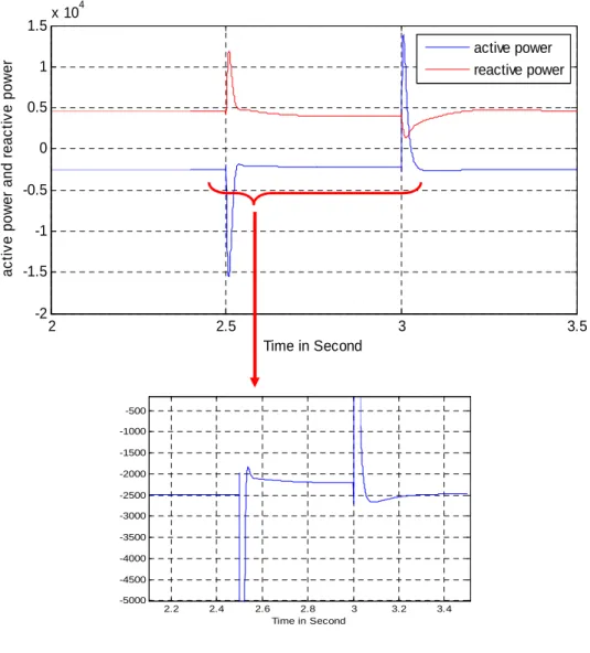
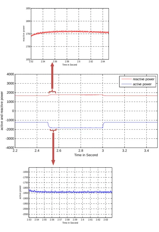
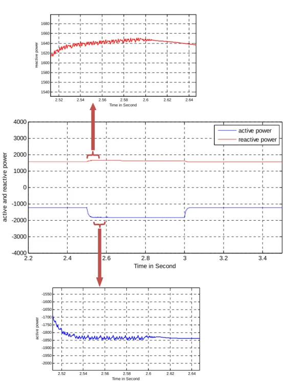
- Active and Reactive Power Responses
- Current Responses
- Speed Responses
- Active and Reactive Power Responses
- Current Responses
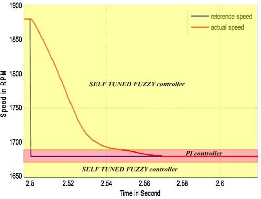
Due to this advantage, the self-tuned fuzzy controller is made active when the system's states are far from their steady state values. Figures and 4.20 show the speed responses of the induction generator with fuzzy controller, self-tuned fuzzy controller and hybrid controller respectively. But the steady state error with self-tuned fuzzy controller is less than that in fuzzy controller, i.e.
Figures and 4.23 show the electromagnetic torque response of an induction generator with soft controller, self-tuning soft controller and hybrid controller respectively. The power factor of induction generator with soft controller, self-tuning soft controller and hybrid controller are given in Figures 4.32 respectively. Page 106 Figures and 4.35 show the phase current response of an induction generator with soft controller, self-tuning soft controller and hybrid controller.
CONCLUSION
Vector control of grid side PWM converter for power factor improvement
INTRODUCTION
MAXIMUM POWER POINT TRACKING
MAXIMUM POWER POINT TRACKING
SUPPLY SIDE CONVERTER CONTROL
VI at the AC input terminals lags behind the source voltage component in phase with Vs. In both maximum power algorithms, the tracking algorithm changes the speed in steps until , where the output power is maximum at point-B. If the wind speed will give off power will jump to point-C, and then maximum power point l bring the operating point to D by seeking the speed.
From point E, the rack algorithm again drives the operating point to point F, which gives the maximum power at a wind speed of Vw2 for a generator speed of ω.
SUPPLY SIDE CONVERTER CONTROL
RESULTS AND DISCUSSION
- Wind velocity Response
- Turbine torque Response
- Direct and quadrature axis current response at generator and grid terminals
- Active and reactive power responses at generator side and grid side
- Phase voltage response at generator side and grid side
The responses of the direct and quadrature axis currents on the grid side are given in Figure 5.12. But Figure 5.18 shows that due to the vector control of the grid side converter, the frequency of the phase current on the grid side also becomes constant. Figure 5.19 shows the phase relationship of the phase voltage on the generator side and the phase current on the generator side.
So the power factor on the generator side remains less than unity as can be seen from Figure 5.21. Figure 5.20 shows the phase relationship of the grid-side phase voltage and the grid-side phase current. So the power factor on the grid side becomes unity which can be seen from Figure 5.21.
CONCLUSION
It can be seen from the figure that the phase current and phase voltage are exactly 180 degrees at the phase difference, due to which the active power becomes negative, i.e.
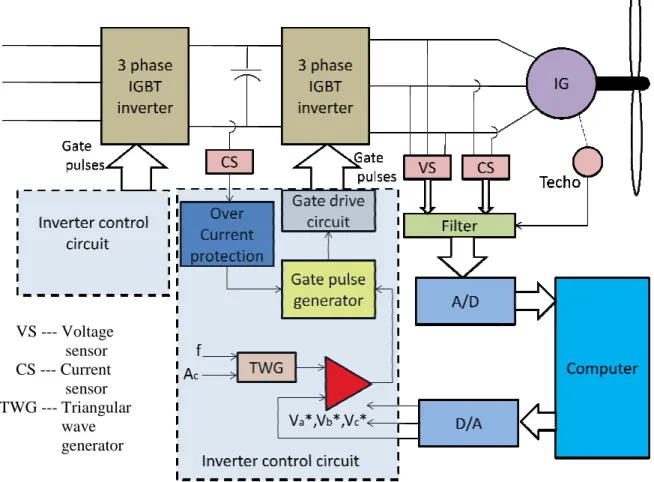
Fabrication and testing of control circuit for a bidirectional converter inverter set
- INTRODUCTION
- POWER ELECTRONIC CONVERTERS
- CONTROL CIRCUIT FOR VSI
- TRIANGULAR WAVE GENERATOR CIRCUIT
- THREE PHASE REFERENCE SINE WAVE GENERATOR
- LOCKOUT CIRCUIT
- FABRICATED CIRCUITS AND TEST RESULTS
- CONCLUSION
The timing diagram for the pulses generated by the latch circuit is shown in Figure 6.8 and Figure 6.9. The output from the gate pulse generator circuit is fed to the gate drive circuit, shown in Figure 6.11. The fabricated lockout circuit is shown in Figure 6.13 and the output of the lockout circuit.
So the output of the latch circuit is not suitable to be used as gate pulses for. So the output of the latch circuit is fed into the gate drive circuit to get the appropriate gate pulses for the inverter. The gate pulses at the output of the gate driver circuit are shown in Figure 6.19.
Conclusion and scope for future work
CONCLUSION
Page 150 reactive power and a conventional PI controller for noise- and error-free steady-state response. With the hybrid controller, the induction generator system gave the best transient and steady state performance. The biggest drawback of a wind power generation system using a cage induction generator is the poor power factor.
Due to the vector control of net side conversion, the supply power factor could be made perfectly equal.
SCOPE FOR FUTURE WORK
Pena, “Sensorless vector control of induction machines for variable speed wind energy applications,” IEEE Trans. Tapia, G.Tapia, J.Xabier Ostolaza, JRSaenz, “Modelling and control of a wind turbine driven doubly fed induction generator” IEEE Trans. Spiegel, “Design and performance evaluation of a fuzzy logic-based variable speed wind generation system,” IEEE Trans.
Radwan, M. Azizur Rahman, “Efficiency of Fuzzy Logic Based Indirect Vector Control for Induction Motor Drive,” IEEE Trans. 14] M.G.Simoes, B.K.Bose, and R.J.Spiegel, “Fuzzy logic-based intelligent control of a variable speed cage wind generation system,” IEEE Trans. Zhou, “Novel self-tuning soft PI control of a novel double salient permanent magnet motor drive,” IEEE Trans.
MACHINE, TURBINE AND SYSTEM PARAMETERS Induction Generator
LIST OF SYMBOLS
Vabcl = Converter line side voltages Vabcs = Grid side line voltages XL = Line inductive reactance δ = Load angle.
LIST OF COMPONENTS USED
Dissemination of Work
BIO-DATA OF THE CANDIDATE