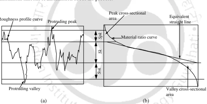
3D surface roughness parameter (Sa (arithmetic mean of absolute height), Spk (reduced peak height), Sk (core roughness depth) and Svk (reduced valley depth)) values of the finished surface provide an understanding of the surface characteristics. The analysis of finishing forces involved in the current MFAF process is performed for better understanding and precise control of the process.
Introduction and Literature survey
Introduction
Magnetic Field Assisted Finishing (MFAF) processes are one of the newly developed finishing processes that use the right composition of polishing fluid. Various freeform surface treatment processes available in the literature are discussed in the following section.
Freeform Surface Finishing Processes
- Grinding
- Honing
- Abrasive Polishing Process
- Electrochemical Finishing Process
- Ball Burnishing Process
- Magnetic Field Assisted Finishing (MFAF) Process
- Magnetic Abrasive Finishing (MAF)
- Magnetorheological Finishing (MRF)
- Magnetorheological Jet Finishing
- Magnetorheological Abrasive Flow Finishing (MRAFF) Process
- Ball End Magnetorheological Finishing (BEMRF) Process
The Magnetic Field Assisted Finishing (MFAF) process uses an external magnetic field for better control of finishing forces. The fluid acts as a conveyor belt in the steering wheel and solidifies with the application of an external magnetic field.
Literature Survey
- Magnetorheological (MR) Fluid
- Workpiece Material
- Experimental Investigation
- Theoretical Investigation .1 Mathematical Modelling
- Force Analysis
The finishing force developed due to the sticking power of the MR polishing fluid and the rotation of the finishing tool. The tangential force is generated by the rotation of the finishing tool, which helps in removing fine chips from the surface of the workpiece.
![Table 1.2 Mechanical properties of Ti alloy (grade 5, annealed) [61]](https://thumb-ap.123doks.com/thumbv2/azpdfnet/10541457.0/34.918.206.664.185.365/table-mechanical-properties-ti-alloy-grade-annealed-61.webp)
Scope and Objectives of the Present Work
Both the magnitude of the normal force and the tangential force decrease as the bending angle increases, however, as the tool rotation speed and workpiece feed speed increase, these forces reach a maximum value and then decrease.
Organization of the Thesis
The ability of the MFAF instrument to provide uniform finishing along the curvature of the freeform surface of a femoral knee implant is analyzed using surface topography and surface roughness. The experimental results will aid in understanding the in vivo performance of the articulating surface of a femoral knee implant finished using the MFAF process.
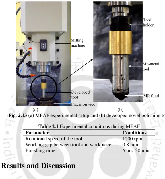
Design and Fabrication of Novel Polishing Tool
- Introduction
- Design and Fabrication of Polishing Tool
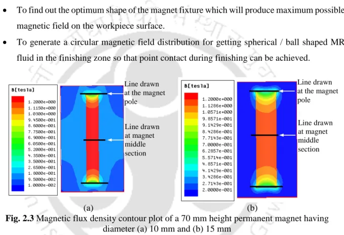
- Dimension of Permanent Magnet
- Shape and Dimension of Magnet Holder
- Experimentation
- Results and Discussion
- Summary
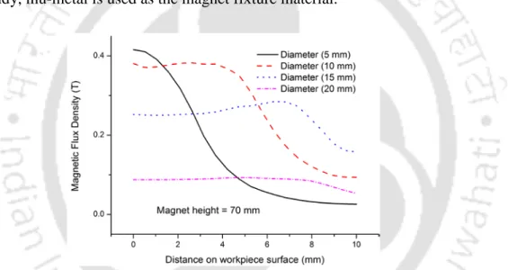
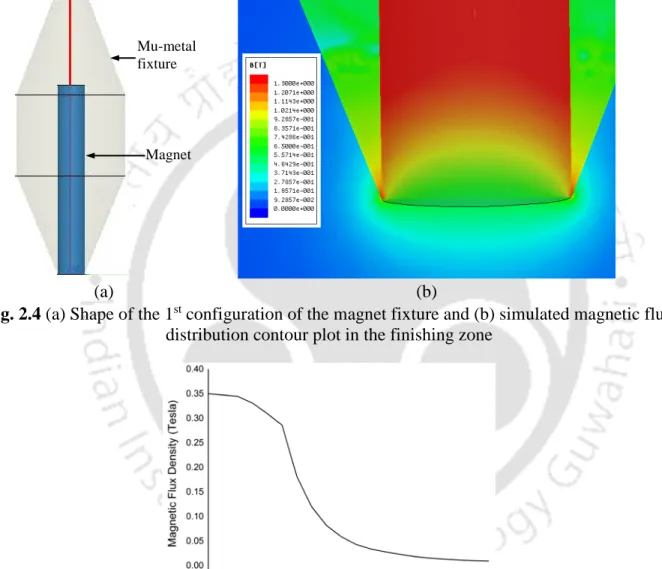
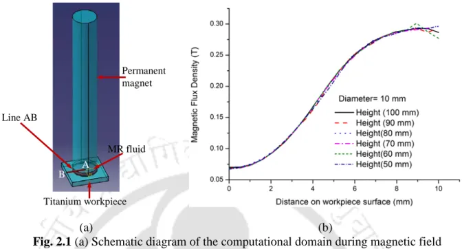
To determine the optimal shape of the magnetic clamp, which will create the largest possible magnetic field on the surface of the workpiece. The magnetic flux density on the surface of the workpiece and the shape of the magnetic field lines at the bottom of the magnetic pole for different configurations of magnetic wiring are simulated to select its optimal configuration. The magnitude of the simulated magnetic field along line AB on the surface of the workpiece indicates that finishing is possible [39].
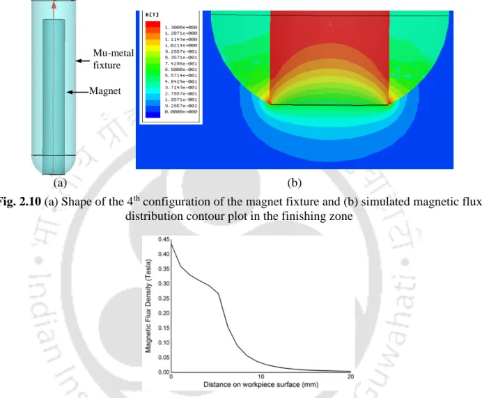
The design of the magnetic device considered for the second configuration is shown in Fig. The magnitude of the simulated magnetic flux density from point A along line AB on the surface of the workpiece is shown in Fig. The magnitude of the simulated magnetic flux density on the workpiece surface from point A along line AB is shown in Fig.
MR fluid synthesis and toolpath generation
- Introduction
- Experimental Investigation
- Results and Discussion
- Effect of Different MR Fluid on Surface Roughness and Surface Topography
- Effect of Different MR Fluid on Wettability of Workpiece
- Formation of Oxide Layer on Workpiece Surface
- Comparison of Experimental Results Using Different Toolpaths
- Summary
3.7 3D surface topography of Ti alloy workpiece surface (a) before and (b) after polishing with MR fluid of type – I. 3.8 2D surface roughness profile of Ti alloy workpiece surface (a) before and (b) after polishing with MR fluid of type – I. Figures 3.10(a) and (b) show the workpiece surface topography before and after finishing, respectively with MR fluid of Type – II.
3.10 3D surface topography of Ti alloy workpiece surface (a) before and (b) after polishing with MR fluid of type – II. 3.11 2D surface roughness profile of Ti alloy workpiece surface (a) before and (b) after polishing with MR fluid of type – II. The contact angle measurement study shows that after finishing with MR fluid of Type - I the obtained surface is hydrophilic in nature.

Characterization of 3D surface parameters of finished surface
- Introduction
- Experimental Investigation
- Results and Discussion
- Effect of Process Parameters on Output Responses
- Confirmation Tests
- Summary
The effect of work gap on 3D surface topography of the workpiece is shown in Fig. The effect of finishing time on 3D surface topography of the workpiece is shown in Fig. 4.6 3D graph showing the combined effect of (a) finishing time & tool rpm and (b) finishing time & work gap on final reduced peak height (Spk); The effect of (c) rpm of the.
4.7 3D graph showing the combined effect of (a) tool rpm and finishing time and (b) finishing time and work gap on final core roughness depth (Sk); The effect of (c) rpm of the. The finishing ability of the abrasive particles grows due to the increase in tool rpm which increases the material removal rate. 4.8 3D graph showing the combined effect of (a) working gap & rpm of the tool and (b) working gap & finishing time on final reduced valley depth (Svk); (c) The effect of job gap.
Investigation of finishing forces
- Introduction
- Simulation Study
- Governing Equations
- Simulation Set-up
- Boundary Conditions
- Mesh Refinement Study
- Experimental Investigation
- Results and Discussion
- Simulation Study and Validation Results
- ANOVA Analysis
- Influence of Process Parameters on Forces
- Summary
Equations (5.2) and (5.3) are used to obtain the BH curve of MR fluid with the data obtained from VSM and this. In the present study, Eq. 5.8) is used to calculate the shear yield stress of MR fluid applied to the finishing site. Fs) acting on abrasive particles is calculated by multiplying the shear yield stress of MR fluid (τy) by the projected finishing point area (Ap), as shown below.
To simulate the MFAF process, an analysis of the effect of the magnetic field on the MR fluid during finishing is mandatory. Rotational motion is provided at both boundaries A and B of the MR fluid brush as shown in the figure. According to ANOVA (Table 5.6), the % contribution of tool revolutions in the case of Fn is small and the change in Fn is almost constant as shown in fig.

Finishing of freeform surface of femoral part of prosthetic knee joint
- Introduction
- Experimental Investigation
- Effect of Surface Curvatures (1 st Set of Experiments)
- Design of Experiments (2 nd Set of Experiments)
- Results and Discussion
- Effect of Surface Curvature on Surface Roughness and Surface Topography
- Analysis of DOE Study
- Effect of Process Parameters
- Summary
6.5 3D surface topographies and surface roughness profiles of femoral knee joint implant in position 1 (a) before and (b) after the MFAF process. 6.6 3D surface topographies and surface roughness profiles of femoral knee joint implant in position 2 (a) before and (b) after the MFAF process. 6.8 3D surface topographies and surface roughness profiles of femoral knee joint implant in position 4 (a) before and (b) after MFAF process.
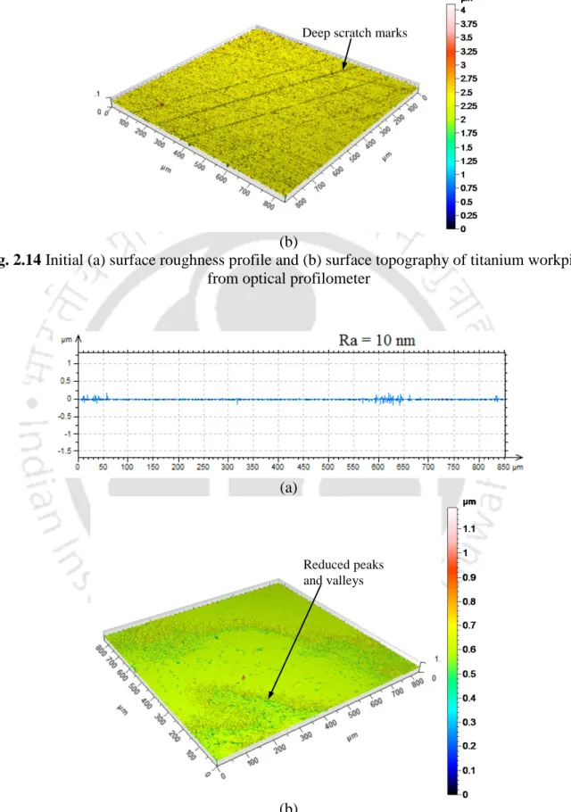
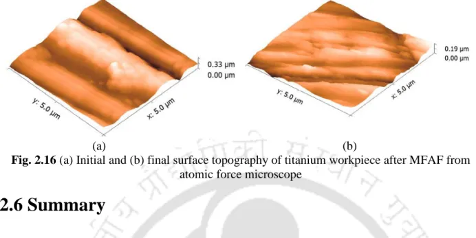
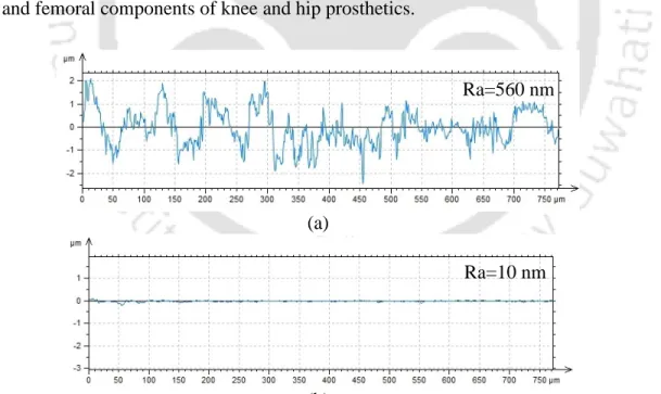
6.9 3D surface topographies and surface roughness profiles of the femoral knee joint implant at position 5 (a) before and (b) after the MFAF procedure. The initial surface roughness (Ra) is 170 nm and eventually decreases to a very low value of 10 nm (Ra). The final surface roughness and surface topography of the femoral knee implant depends on the rotational speed of the MFAF tool.

Performance analysis of finished Ti alloy for femoral knee implant application
- Introduction
- Experimental Investigation
- Results and Discussion
- Volume Loss Analysis
- Wear Rate Analysis
- Surface Analysis
- Summary
The weight and volume loss of the UHMWPE disc after the wear test for the MFAF and HP pins is given in Table 7.3. The volume loss calculated from the corresponding weight loss data of the UHMWPE disc after the wear test is given as Also, the wear trace formed on the UHMWPE plate after the wear test is analyzed using an optical surface profilometer.
7.5(ii)) are observed in all HP pins after the wear test due to the higher initial surface roughness of the HP pins. The trace of wear on the UHMWPE disc after the wear test is given in Fig. 7.6 (a) Surface topography of the UHMWPE disc before the wear test and (b) wear marks on the UHMWPE disc after the wear test.
Conclusions and scope for future work
Conclusions
- Preliminary Investigation .1 MFAF Tool Development
- Synthesis of Optimum MR Fluid
- Optimum Toolpath Generation
- Experimental Investigation .1 Finishing of Flat Surface
- Finishing of Freeform Surface
- Force Analysis
- Tribological Study
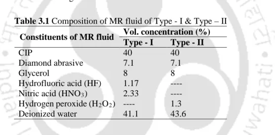
The base medium components of type I MR fluid are hydrofluoric acid (HF), nitric acid (HNO3), and deionized water. In the case of type II MR fluid, the base medium consists of hydrogen peroxide (H2O2) and deionized water. The surface obtained after the final treatment with MR liquid type – I is smoother (it has a surface roughness of 10 nm) with a smaller number of dimples and depressions than with MR liquid type – II.
From the wettability study of the final surface using a goniometer, it was found that the surface treated with type I MR fluid is hydrophilic in nature, while type II MR fluid is hydrophobic. Type – II MR fluid is more suitable for permanent implants such as dental implants as it provides better chances of osseointegration due to the acquired surface characteristics of relatively higher surface roughness (Ra–70 nm) with hydrophobic nature. From an experimental study, it was found that CIP chains break at high revolutions due to shear thinning of the MR fluid.
Scope for Future Work
Tribological studies are conducted to analyze the performance of MFAF polished surface compared to manually polished surface of UHMWPE disc used in prosthetic implants. It can be speculated from the wear analysis that the wear of the UHMWPE bearing surface will be less with MFAF polished femoral component. From surface roughness analysis, it can be assumed that the wear of UHMWPE bearing surface will be less with MFAF polished femur component.
The wear track analysis shows that more deep scuff marks are generated in the tread when using hand/manual polished pins than MFAF pins for the same wear test duration. The MR fluid behavior during post-processing under the MFAF tool can be further modeled using various simulation techniques to gain a better understanding of the process mechanism. An in-depth tribological study can be performed to analyze the performance of polished femoral knee implant by MFAF process.
Investigation of an Internal Magnetic Abrasive Finish Using a Pole Rotation System: Discussion of the Characteristic Abrasive Behavior. Effect of work gap and peripheral speed on the performance of magnetic abrasive finishing process. Effect of extrusion pressure and number of finishing cycles on surface roughness in magnetorheological abrasive flow finishing (MRAFF) process.
Design and manufacture of a new polishing tool for the finishing of freeform surfaces in the Magnetic Field Finishing (MFAF) process. Nano-finishing of a bio-titanium alloy to create different surface morphologies by varying the magnetorheological polishing fluid composition. Tool path generation and finishing of a biotitanium alloy using a new polishing tool in the MFAF process.
Papers published in Journals
Papers communicated to Journals
Papers published in Conference Proceedings
Pritam Akhuly, Anwesa Barman, Manas Das, Heat Transfer Analysis of Magnetorheological Fluid in Magnetic Field assisted Finishing Process, International Conference on Precision, Meso, Micro and Nano Engineering (COPEN-9), IIT Bombay, December Paper ID 68. Anwesa Barman , Manas Das, Design and Development of New Polishing Tool for Finishing Freeform Surfaces in Magnetic Field Assisted Finishing Process, International Conference on Precision, Meso, Micro and Nano Engineering (COPEN-9), IIT Bombay, December Paper ID 70. Anwesa Barman , Pritam Akhuly, Manas Das, Analysis of heat generation in magnetorheological polishing medium during finishing in magnetic field assisted finishing process, 68th Annual Session of Indian Institute of Chemical Engineers (CHEMCON December, 2015, Guwahati, India, Paper ID FM-095.
Anwesa Barman, Manas Das, Optimizing tool path generation in a magnetic field assisted finishing process during nanofinishing of biomaterials with a novel tool, Proc. Anwesa Barman, Manas Das, Analysis of forces during spot finishing of titanium alloy using a new tool in magnetic field assisted finishing process, Proc.
Published book chapter