This is to certify that the thesis entitled "Controller Design Methods for Linear Systems with Emphasis on Process Integration", submitted by Ahmad Ali, a Research Scientist in the Department of Electronics and Communication Engineering, Indian Institute of Technology Guwahati, for the award of the degree of Doctor of Philosophy, is a record of an original research work carried out by him under my supervision and guidance. The thesis met all requirements according to the regulations of the Institute and in my opinion reached the standard required for submission. I am grateful to all the other faculty members and staff of the Department of ECE.
The parameters of the proposed proportional-integral-derivative (PID) controllers and its variants are optimized by minimizing the integral squared error (ISE) using the so-called bacterial feeding algorithm (BFA). Next, the parameters of the PID and its variants are estimated using the proposed 'slope of the Nyquist curves' technique. The approach of the mentioned slope of the Nyquist curves method is also extended to design controllers for the modified Smith predictors.
Finally, the parameters of the PID and its variants are derived analytically using the user-defined percentage exceedance and process model parameters.
Nomenclature
Mathematical Notations
Tdm Average of the derivative time constant obtained in several runs of evolutionary algorithm Ti Integral time constant. Tim Average of the integral time constant obtained in several runs of evolutionary algorithm u(t) Control signal.
List of Publications
Introduction
- Introduction
- INTRODUCTION 2
- TYPES OF FEEDBACK CONTROLLERS 3
- Types of Feedback Controllers
- TYPES OF FEEDBACK CONTROLLERS 4 performance, but at the same time increases gain at high frequencies. This means that the high
- TYPES OF FEEDBACK CONTROLLERS 5
- PROCESS CONTROL REQUIREMENTS 6
- Process Control Requirements
- PROCESS CONTROL REQUIREMENTS 7 to M s by the following equations
- Controller Design
- Motivation of the Present Work
- OUTLINE OF THE THESIS 10
- Outline of the Thesis
- OUTLINE OF THE THESIS 11 and it is observed that the percentage overshoot remains constant for a particular value of M s
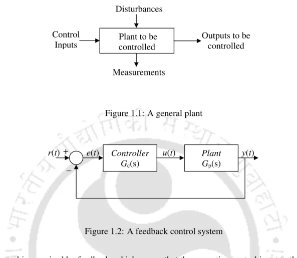
These considerations suggest the following general layout of the plant or system to be inspected. The steady-state error of a system depends on the number of poles at the origin of the s-domain feedforward loop transfer function. Since a PI controller introduces an integrator or a pole at the origin, any steady-state error of the system at a step input will be eliminated by the controller.
To eliminate this problem, a noise filter is usually used with the derivative action of the controller, and the transfer function of the PID controller becomes When the classical PID controller is implemented in the forward path of the closed-loop system, the control action can be written as However, none of the methods provide the settings for integration plus time delay (IPTD), integration plus first order plus time delay (IFOPTD) and double integration plus time delay (DIPTD) process models, respectively.
The parameters of the PID controller are obtained to achieve a user-specified Me in Chapter 5.
Controller Design based on Bacterial Foraging Algorithm
Introduction
INTRODUCTION 13 The classical methods used for optimization in [17,19,31] are highly sensitive to starting points
Integral Performance Criterion
INTEGRAL PERFORMANCE CRITERION 15
- Evaluation of Modified Objective Function in the Frequency Domain
BIO-INSPIRED ALGORITHMS 16
Bio-Inspired Algorithms
- Particle Swarm Optimization
BIO-INSPIRED ALGORITHMS 17 where v ip and x ip represent the velocity and position of ith particle in the pth dimension,
- Bacterial Foraging Algorithm
BIO-INSPIRED ALGORITHMS 18
Number of chemotactic steps, Nc 3. Number of chemotactic steps, Nc. Number of reproduction steps, No.
BIO-INSPIRED ALGORITHMS 20
AN ADAPTIVE STRATEGY FOR RUN LENGTH VECTOR 21
An Adaptive Strategy for Run Length Vector
SELECTION OF WEIGHTING FACTOR 22
Selection of Weighting Factor
Simulation Study
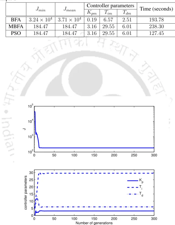
- Example 1
SIMULATION STUDY 24 J min , J mean , mean values of the controller parameters and the time taken in seconds for 25 trial
- Example 2
SIMULATION STUDY 25
A NEW OBJECTIVE FUNCTION FOR CONTROLLER TUNING 26
A New Objective Function for Controller Tuning
A NEW OBJECTIVE FUNCTION FOR CONTROLLER TUNING 27
A NEW OBJECTIVE FUNCTION FOR CONTROLLER TUNING 28
A NEW OBJECTIVE FUNCTION FOR CONTROLLER TUNING 29
A NEW OBJECTIVE FUNCTION FOR CONTROLLER TUNING 30 therefore proposed by modifying the ISE criterion and is given by
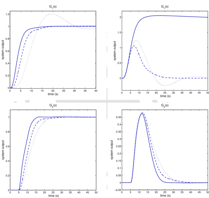
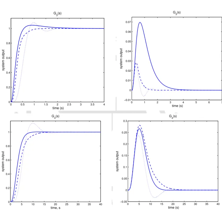
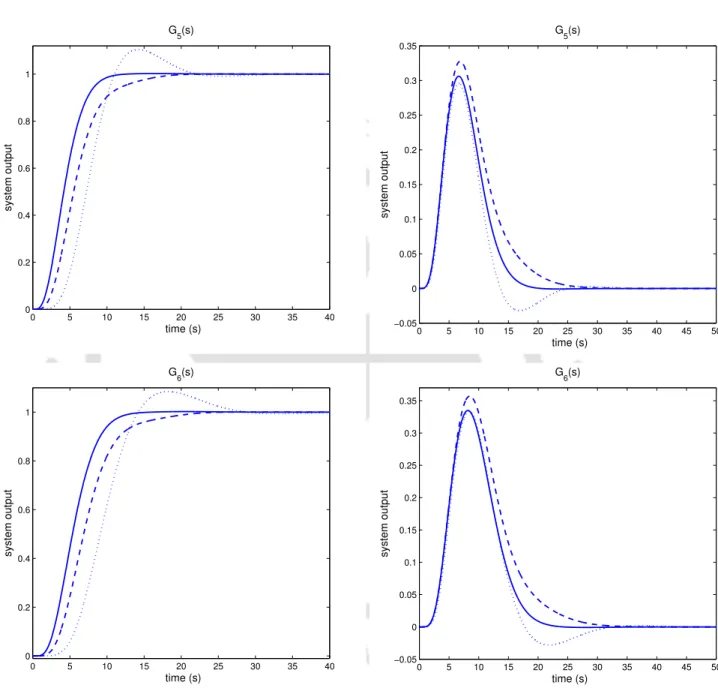
- Simulation Study
A NEW OBJECTIVE FUNCTION FOR CONTROLLER TUNING 31 transfer functions represent processes with large variations in plant dynamics, the resulting setpoint
A NEW OBJECTIVE FUNCTION FOR CONTROLLER TUNING 32
A NEW OBJECTIVE FUNCTION FOR CONTROLLER TUNING 33
A NEW OBJECTIVE FUNCTION FOR CONTROLLER TUNING 34
A NEW OBJECTIVE FUNCTION FOR CONTROLLER TUNING 35
CONCLUSIONS 36
Conclusions
Controller Tuning for Integrating Processes
Introduction
Integrating Process Models
Loop Slope Adjustment
LOOP SLOPE ADJUSTMENT 39
- Selection of Gain Crossover Frequency
- PID Controller
LOOP SLOPE ADJUSTMENT 40 Differentiating the above equation, we get
LOOP SLOPE ADJUSTMENT 41
- IPTD Process Model
- IFOPTD Process Model
LOOP SLOPE ADJUSTMENT 42
- DIPTD Process Model
- PI Controller
Integral Performance Criteria
INTEGRAL PERFORMANCE CRITERIA 44
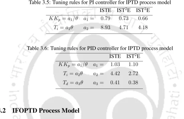
- IPTD Process Model
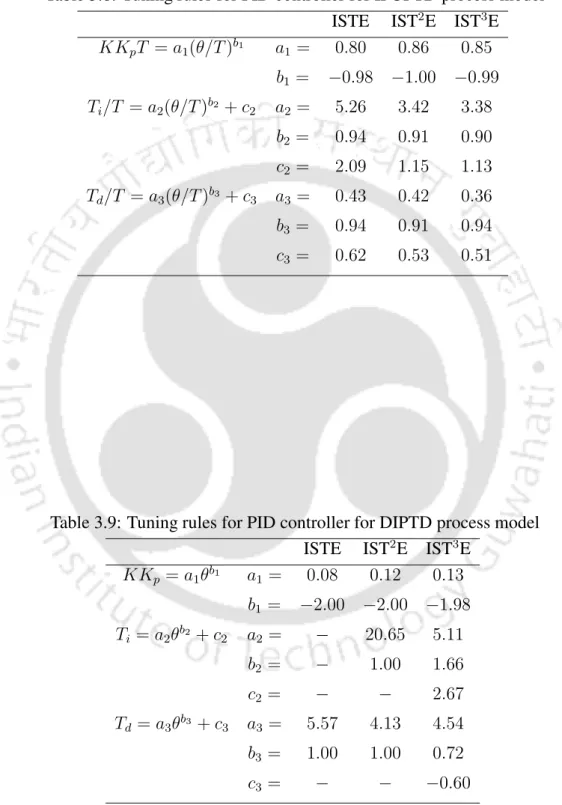
- IFOPTD Process Model
- DIPTD Process Model
INTEGRAL PERFORMANCE CRITERIA 45
SIMULATION STUDY 46
Simulation Study
SIMULATION STUDY 47 and it is observed that the robustness to the assumed parameter perturbation is very satisfactory
SIMULATION STUDY 48
SIMULATION STUDY 49
SIMULATION STUDY 50
SIMULATION STUDY 51
A New Objective Function
A NEW OBJECTIVE FUNCTION 53
A NEW OBJECTIVE FUNCTION 54
A NEW OBJECTIVE FUNCTION 55
A NEW OBJECTIVE FUNCTION 56 was recommended for integrating plant models. In this section, analytical expressions correlating
- IPTD Process Model
- IFOPTD Process Model
A NEW OBJECTIVE FUNCTION 57
- Simulation Study
Conclusions
CONCLUSIONS 59
Modified Smith Predictor for Integrating Processes
- Introduction
- INTRODUCTION 61 and long dead time. A new Smith predictor that isolates the setpoint response from the load distur-
- MODIFIED SMITH PREDICTOR 62
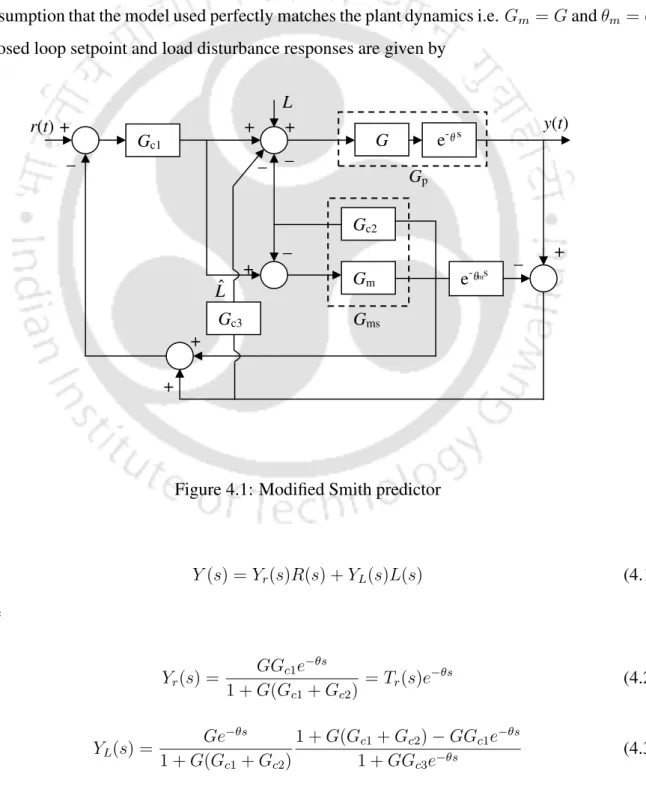
- Modified Smith Predictor
- Controller Design for Integrating Processes
- Design of G c 1
- CONTROLLER DESIGN FOR INTEGRATING PROCESSES 64 The parameters of the PI controller can be obtained from the above equations for a given ω n . Time
- CONTROLLER DESIGN FOR INTEGRATING PROCESSES 65 plant model
- Design of G c 3
- CONTROLLER DESIGN FOR INTEGRATING PROCESSES 66 The slope of the Nyquist curve at ω o is given by
- Selection of Tuning Parameters
- Simulation Study
- SIMULATION STUDY 68 The effect of rise time on system robustness is studied by simulating the system responses for
- SIMULATION STUDY 69
- SIMULATION STUDY 70
- SIMULATION STUDY 71
- SIMULATION STUDY 72
- Conclusions
- CONCLUSIONS 74
- CONCLUSIONS 75
- CONCLUSIONS 76
- CONCLUSIONS 77
- CONCLUSIONS 78
- CONCLUSIONS 79 processes as compared to some of the recently reported approaches in the literature. The controller
In this chapter, the modified Smith predictor proposed in [28] is discussed, and the parameters of the PD controller used for load disturbance rejection are obtained by fitting the slope of the Nyquist curve at the gain transition frequency. Guidelines are given for selecting the gain crossover frequency and the slope of the Nyquist curve. Assuming that Gc1 is a PI controller and using (4.2), we obtain the delay-free part of the closed-loop transfer function for servo tracking as .
CONTROLLER DESIGN FOR INTEGRATION OF PROCESSES 64 The parameters of the PI controller can be obtained from the above equations for a given ωn. Time The parameters of the PI controller can be obtained from the above equations for a given ωn. The delay-free part of the closed-loop transfer function for servo control adopting Gc1 as a parallel PID controller is given by.
Then the parameters of the PID controller are estimated by following the procedure given in the above case (ii). The derived time constant of the PD controller can be obtained from (4.23) for a given ωo = ωg and ψ. There are four tuning parameters: rise time (tr), gain crossover frequency (ωg), slope of the Nyquist curve, and β.
It can be observed that the robustness of the proposed design technique against assumed parameter perturbation is satisfactory. To show the robustness of the proposed method, the results are also compared with Rao et al. s method and the corresponding step responses and the corresponding control signals are shown in Figs 4.12 and 4.13 respectively. In this work, it is shown that the three controllers of the modified Smith predictor proposed in the literature, if properly tuned, give improved closed-loop performances for a class of integration.
The controller's processes compared to some of the recently reported approaches in the literature. The PD controller considered for load disturbance rejection is tuned to achieve a user-specified slope of the Nyquist curve at gain crossover frequency.
Controller Tuning Based on Percentage Overshoot Specification
Introduction
INTRODUCTION 81 maximum sensitivity (M s ) and / or complementary sensitivity. The system output corresponding
Controller Design
- Stable FOPTD Process Model
CONTROLLER DESIGN 83
- Selection of T d
As in this work, the controller parameters are taken to achieve the user-defined percent overshoot, the Kpt values resulting in no overshoot are shown in bold in Table 5.1. CONTROLLER DESIGN 85 of 0.05 and the values of q and the corresponding percent overshoots are given in the third.
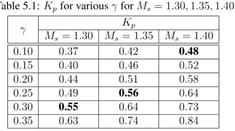
CONTROLLER DESIGN 85 of 0.05 and the values of q and the corresponding percentage overshoots are given in the third
CONTROLLER DESIGN 86
- IPTD Process Model
CONTROLLER DESIGN 87
- Properties of the Tuning Method
SIMULATION STUDY 88
Simulation Study
- Examples
SIMULATION STUDY 89 setpoint and a negative step input of 1 in the load at time t = 20 seconds. The simulation results
SIMULATION STUDY 90
SIMULATION STUDY 91
SIMULATION STUDY 92
SIMULATION STUDY 93
SIMULATION STUDY 94
Controller Design in IMC Framework
CONTROLLER DESIGN IN IMC FRAMEWORK 96
- Limitations of IMC based Controller Design
CONTROLLER DESIGN IN IMC FRAMEWORK 97 Table 5.13: Proposed PID parameters
- Simulation Study
DESIGN OF THE CONTROLLER IN THE IMC 985.14 FRAME shows the plant outputs for the unit change in the step input and the unit scale change in the load.
CONTROLLER DESIGN IN IMC FRAMEWORK 98 5.14 show the plant outputs for a unit change in the step input and a unit step change in the load
CONTROLLER DESIGN IN IMC FRAMEWORK 99
CONTROLLER DESIGN IN IMC FRAMEWORK 100
CONTROLLER DESIGN IN IMC FRAMEWORK 101
CONTROLLER DESIGN IN IMC FRAMEWORK 102
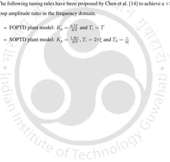
COMPARISON OF PI AND PID TUNING RULES 103
Comparison of PI and PID Tuning Rules
Conclusions
CONCLUSIONS 104
CONCLUSIONS 105
Conclusions and Future Work
- Concluding Remarks
- Thesis Contributions
- DIRECTIONS FOR FUTURE WORK 108
- Directions for Future Work
The setpoint tracking controller is designed to approximate the delay-free approach in the literature. The setpoint tracking controller is designed so that the delay-free component of the system output follows the response of a second-order installation, assuming a perfect match between the actual installation and the model, both in terms of dynamics and time delay. The PD controller considered for load disturbance suppression is tuned to achieve a user-specified slope of the Nyquist curve at the gain crossover frequency, and a unity gain proportional controller is considered for stabilizing of the integrating factory models.
Finally, the thesis addresses the controller design problem for stable FOPTD and SOPTD plant models such that the response of the compensated system falls below a specified value. Analytical expressions correlating the controller parameters with percentage overshoot and factory model parameters are given and it is shown that the PD controller provides better servo control performance for integrating processes. The approach is also extended to the IMC framework to obtain the normalized IMC filter time constant as a function of the percentage exceedance.
The main contributions of the work are presented in Chapters 2 to 5 and the conclusions of the study are given at the end of each chapter. Tuning formulas for the setpoint tracking controller as a function of the damping ratio and the natural frequency. Mathematical analysis of the chemotaxis step of BFA to study convergence properties will be an interesting and useful area of research.
A PD controller gives better servo performance for integrating processes, while a PID is needed for load disturbance rejection. Therefore, the proposal of a two degree of freedom control architecture for the satisfactory closed loop operation of the integration of processes warrants further investigation. Set formulas for unstable plant models by minimizing higher versions of ISTE criterion and a comparison with the latest reported approaches to find their suitability can be performed.
Controller tuning based on maximum sensitivity can be extended to non-minimum phase plants in the IMC framework. Analytical expressions correlating PD parameters to plant model parameters and percent overshoot can also be obtained for IFOPTD and DIPTD process models.
Appendix A
Selection of Performance Criterion
IPTD PROCESS MODEL 110
IPTD Process Model
- PI Controller
IPTD PROCESS MODEL 111
- PID Controller
IFOPTD PROCESS MODEL 112
IFOPTD Process Model
- PI Controller
IFOPTD PROCESS MODEL 113
- PID Controller
DIPTD PROCESS MODEL 114
DIPTD Process Model
Appendix B
A Brief Review of Related Controller Design Schemes
This approach allows the desired maximum overshoot, phase and gain margins, and bandwidth of a closed-loop system to be achieved simultaneously. Visioli [13] proposed PD/PID controllers for setpoint tracking and load disturbance rejection for IPTD plant models by minimizing ISE, ITSE and ISTE performance criteria. Kaya [6] proposed a model-based PI-PD controller design for integration and unsteady plant models, where PD feedback is used to change the poles of the plant transfer function to more desirable locations for PI controller control.
The ISTE standard forms are used to obtain the parameters of the PI-PD controller, as they allow the design to be completed by simple algebra. PID tuning rules based on looping H infinity control were proposed by Tan et al. The controller parameters are obtained by using one design parameter that reflects the trade-off between robustness and time-domain performance of the closed-loop system, thus making it convenient to select the controller parameters in light of uncertainties in the plant parameters.
The settings for P, PI and PID controllers that take into account the characteristics of the closed loop response in particular, the percentage of overshoot are presented in [12]. The controller parameters are obtained in terms of plant model parameters by specifying the desired closed-loop transfer function to follow an underdamped trajectory and by a suitable.
Appendix C
Why a PI controller fails to stabilize a DIPTD plant model?
Bibliography
Chidambaram, “Direct synthesis-based controller design for integrating time-delayed processes,” to appear in Journal of the Franklin Institute, 2008. 11] ——, “Setpoint-weighted modified Smith predictor for integrating and dual integrating processes with time delay," ISA Transactions, vol. Budman, "Optimal Tuning of PID Controllers for FOPTD, SOPTD, and SOPTD with Main Processes," Chemical Engineering and Processing, vol.
Sree, “A Simple Tuning Method of PID Controllers for Integral/Dead-Time Processes,” Computers and Chemical Engg., vol. Lee, “Analytical design of improved PID filter controller for integration and first-order unsteady processes with time delay,” Chemical Engineering Science , vol. Lim, “A new Smith predictor for the control of a process with an integrator and long dead time,” IEEE Trans.
Egan, “Extension and partial optimization of a modified Smith predictor and controller for unsteady time-delay processes,” Int. Kaya, “Two-degree-of-freedom IMC structure and process integration controller design based on gain and phase edge specifications,” IEE Proc. Mici´c, “Modified Smith predictor for process control with integrator and long dead time,” IEEE Trans.
62] ——, “On the modified Smith predictor for controlling a process with an integrator and long dead time,” IEEE Trans. Liu, “Simple Method for Integrating Long Dead-Time Processes,” Journal of Process Control, vol Camacho, “A Unified Approach to the Design of Dead-Time Compensators for Stable and Integrating Dead-Time Processes,” IEEE Trans.
Zhang, “New modified Smith predictor scheme for integration and unsteady processes with time delay,” IEE Proc. Zhang, “Analytical decoupling control design for dynamic plants with time delay and dual integrators,” IEE Proc.


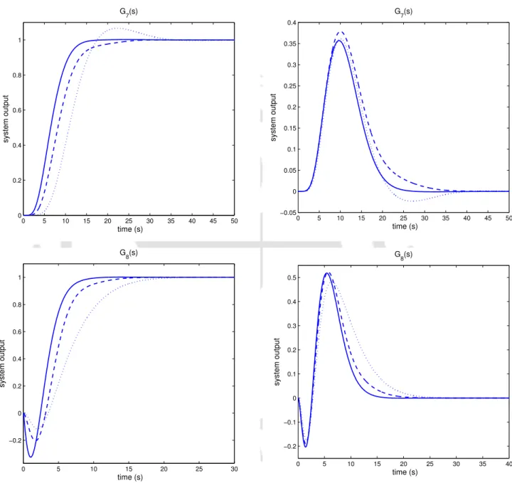
![Figure 3.1: Step responses for Example 1: ( − ) IST 3 E, (...) KPGM [4], ( −− ) Slope method and ( −](https://thumb-ap.123doks.com/thumbv2/azpdfnet/10434315.0/66.892.134.815.143.1076/figure-step-responses-example-ist-kpgm-slope-method.webp)
