Overview of 3D Printing of Thermoelectric Materials and Power-Generating Devices
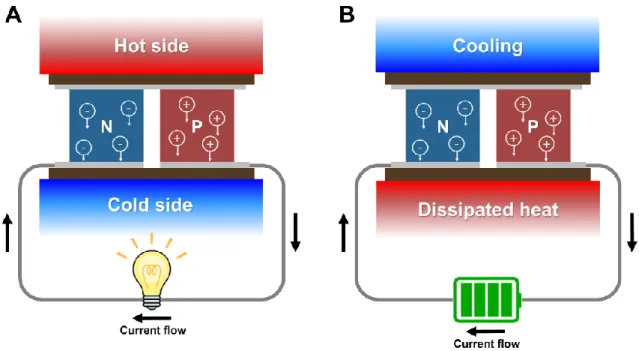
Thermoelectric energy conversion
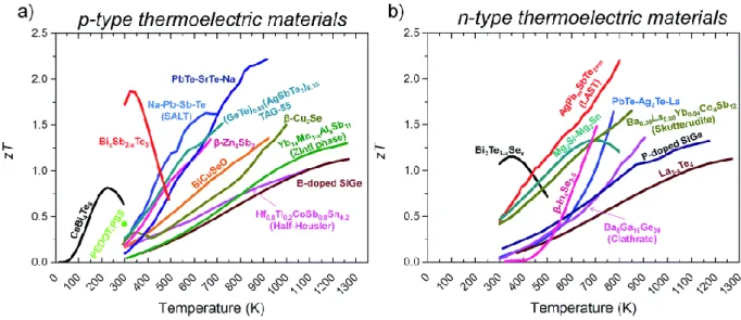
- Thermoelectric materials
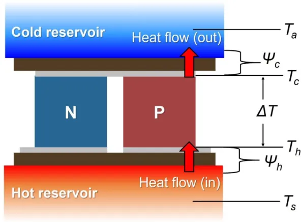
- Thermoelectric generators
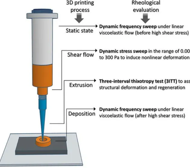
- Rheological properties of thermoelectric inks
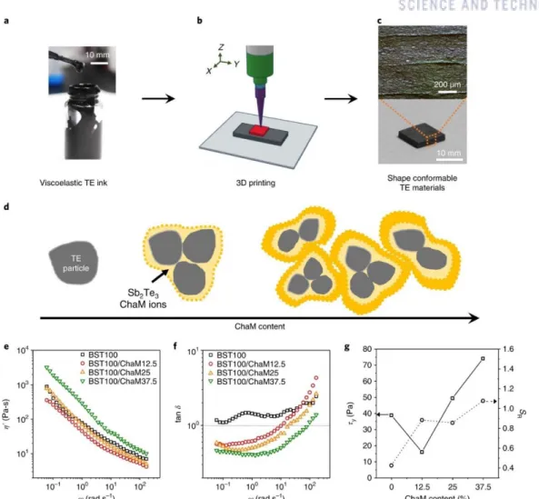
3D printing of shape-conformable thermoelectric materials using all-inorganic
Results and discussion
Addition of a small amount of ChaM binders (yellow) resulted in localized aggregation of BiSbTe particles (grey), reducing their effective volume. Temperature-dependent TE properties of n-type and p-type 3D-printed cubes: electrical conductivity and absolute Seebeck coefficient (d), thermal conductivity (e) and zT (f). Photo showing a printed sample before drying from TE ink with 10 wt. % ChaM.
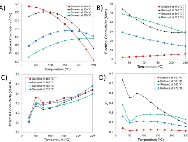
The room temperature electrical conductivity and Seebeck coefficients of the 3D printed p-type cuboid, disk and half-ring are 55375 S/m and 165 μV/K with an uncertainty of 0.8~1.5% (Figure 2.7a). The temperature dependence of TE properties was characterized by 3D printed n-type and p-type cuboids with a width of 10 mm and a thickness of 1.5~2.0 mm. The electrical conductivity of the n-type and p-type samples was in the range of S·m-1 and decreased with increasing temperature (Figure 2.7d).
These ultra-low thermal properties can be understood by considering the porosity of the 3D printed materials. Also, the relatively high carrier mobility of the 3D printed TE materials further supported the existence of pores at the macroscale. Comparison of TE properties of the 3D printed samples with the hot-pressed samples with similar compositions and (c) thermal conductivity.
Schematic representation of the temperature distributions of the half-ring based conformal TEG (a) and the conventional planar TEG calculated by the FEM (b). c) Output voltage per thermocouple (top) and output power (bottom) of the conformal cylindrical TEG as a function of the temperature difference obtained by FEM (line) and experiment (symbol). The calculated values of the electrical output of the half-ring based conformal TEG showed good agreement with the experimental values (Figure 2.15c).
Conclusion
The half-ring-based TEG was predicted to exhibit 3 to 6 times greater output voltage per TE pair and an order of magnitude greater output power than the planar TEGs (Figure 2.16a). Although the Seebeck coefficient per TE pair in the half-ring based TEG (~300 μV·K-1) was smaller than that of the planar TEGs (~400 μV·K-1), a larger ΔTTE in the half-ring-based TEG resulted in greater output. For this comparison, we neglected the ρc in both TEG types, because the ρc value in the planar TEGs was unknown.
Planar TEGs with different wEpoxy values showed only a small difference in electrical output as the ΔTTE values in these TEGs were similar (Figure 2.15b). The half-ring-based TEG had ~5 times greater heat dissipation from the glow tube (Qtube) and ~3 times greater heat absorption in the TE legs (QTE) compared to the planar TEG. Since the heat rate is inversely proportional to the thermal resistance (Rth), this result indicates that the thermal resistance between the water and the bottom of the TE legs (Rth, hot) was much smaller in the half-ring TEG.
Thus, further reducing the thermal resistance (e.g., with a smaller thickness of the TE legs or by improving the convection at the air-TEG interface) would improve the QTE/Qtube ratio. For the half-ring based TEG, ηTE > 2% and ηSystem > 0.2% in the corresponding temperature range. Although the efficiency was still smaller than the Carnot efficiency (ηCarnot > 3%), it could be improved by optimizing the TE materials and the thermal design of the system.
These computational and experimental results suggest that heat source-compatible TE materials achieved by 3D printing can be an alternative way to increase the efficiency of the TEG system. Finally, I believe that the currently developed 3D printing technology will be widely used to advance the design of inorganic materials in the fields of energy, electronics and electronic art.
Experimental section
The dynamic rheological properties of the TE inks were measured with a rheometer (Haake MARS. Ⅲ, Thermo Scientific) at 25 oC in a parallel plate geometry with a diameter of 35 mm. Three pairs of Cu electrodes were attached on top of the alumina tube with an inner diameter of 5 mm and an outer diameter of 8 mm. Two T-type thermocouples were attached to the surface of the alumina tube (hot side) and to the Cu electrode (cold side) to measure their temperature difference.
To measure the internal resistance (R), the device was connected to an ammeter in series and a voltmeter in parallel. The electrical conductivity at room temperature of the 3D printed samples was measured by a 4-terminal Van der Pauw method (Keithley 2,400 meter-source controlled Lab trace 2.0 software, Keithley Instrument, Inc.). The Seebeck coefficients of the 3D printed samples at room temperature were determined by measuring the open circuit voltage in the temperature gradient applied by a commercial Peltier cooler in contact with the samples.
Typically, six data points were acquired with temperature differences ranging from ±1 oC to ±5 oC, and the Seebeck coefficient was estimated from the slope of the voltage-temperature difference curve. The measurements of temperature-dependent electrical conductivity and Seebeck coefficient were performed using commercial equipment (ZEM-3, Ulvac-Riko) in the temperature range from 25 °C to 225 °C under a low-pressure helium atmosphere. The coefficient ha used in the calculation was varied to produce the same temperature on the cold side of the half-ring based TEG as in the experiment (~ 30 oC).
Based on the properties of commercial TE materials, I assumed that the TE element had a Seebeck coefficient of 197 V·K-. Rth between water and bottom of TE elements (Rth, hot), Rth across TE elements (Rth, TE) and Rth between top of TE elements and air (Rth, cold).
Direct ink writing of three-dimensional thermoelectric microarchitectures
Results and discussion
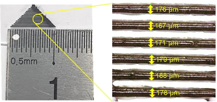
Illustrated model (h) and photograph (i) of the 3D lattice constructed by the layer-by-layer deposition of TE filaments. The OM and scanning electron microscopy (SEM) images of the sintered filaments in the printed 3D lattice (Figure 3.1k, l) revealed that the TE filaments retained their primary architecture. The degree of oxidation of the TE particles was investigated by ζ-potential measurement, Fourier transform infrared spectroscopy (FTIR) and X-ray photoelectron spectroscopy (XPS) (Figure 3.4 d,e, Figure 3.6).
Comparison of the room temperature electrical conductivity (b) and the Seebeck coefficient (c) of the p-type and n-type 3D printed filaments and bulk beams. Temperature-dependent TE properties of the n-type and p-type 3D printed samples: electrical conductivity and absolute Seebeck coefficients (d), thermal conductivity (e), and zT values (f). Temperature-dependent TE properties of the p-type Bi0.55Sb1.45Te3 3D printed cubes with different ChaM contents: electrical conductivity and absolute Seebeck coefficient (a), thermal conductivity (b) and zT (c).
Temperature-dependent TE properties of 3D-printed n-type Bi2Te2.7Se0.3 cuboids with different ChaM content: electrical conductivity and absolute Seebeck coefficient (d), thermal conductivity (e) and zT (f). The electrical conductivity of p- and n-type samples decreased with increasing temperatures, indicating the degenerate behavior of semiconductors. These macroscale pores are useful for increasing zT values by reducing thermal conductivity.
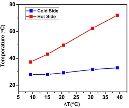
Temperatures on the hot and cold sides of the μ-TEG in the measurement setup during heating. The creation of such a high temperature difference in the current system is attributed to the high aspect ratio of the 3D printed TE legs.
Conclusion
Experimental section
6년이 지난 것 같습니다. 제 마음을 다 표현할 수는 없지만, 이 편지를 통해 모든 분들께 감사의 마음을 전하고 싶습니다. 먼저, 저에게 배우고 성장할 수 있는 기회를 주신 지도교수님 손재성 교수님께 진심으로 감사드립니다.
좋은 연구를 할 수 있는 기회를 주시고 항상 믿어주셔서 너무 감사드립니다. 저에게 주신 진심어린 조언과 격려의 말씀 잊지 않고 평생 명심하며, 선생님의 본을 따라 정말 훌륭한 연구자이자 어른이 되도록 하겠습니다. 차채녕교수님, 채한기교수님, 이지은교수님, 이학박사님께 감사드립니다. 바쁜 와중에도 저의 박사논문을 검토해주신 김경태 선생님.
교수님, 의사들과 공동연구를 할 수 있어서 큰 영광이었고, 그 과정에서 많은 것을 배울 수 있었던 것 같습니다. 그리고 학위심사 때 주신 소중한 조언들 잊지 않고 늘 생각하겠습니다. 박사. 재료과학원의 김경태 선생님께서 좋은 자료를 제공해 주셔서 좋은 논문을 쓰는 데 큰 도움이 되었습니다.
그리고 항상 저를 웃게 해주신 UNIST 차채녕 교수님, 제 논문을 검토해주시고, 만날 때마다 항상 행복하게 해주셔서 감사드립니다. 또한, 이 훌륭한 논문을 집필하는데 많은 도움을 주신 주혜진 연구원과 김선태 연구원에게도 진심으로 감사의 말씀을 전하고 싶습니다.