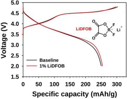
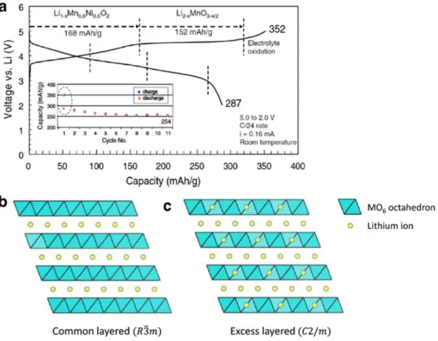
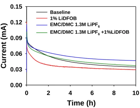
Electrochemical profile and crystal structure of lithium-rich cathode. a) Initial charge/discharge profiles of the Lithium-rich cathode. Voltage profiles of Li/Li-rich cathode half-cells with basic electrolytes and 1% LiDFOB during precycling at 25 oC. Potentiostatic profiles at constant voltage of 4.9 V for 10 h after charging to 4.9 V of Li/Li-rich cathode half-cells with basic electrolytes and 1% LiDFOB at 25 oC.
Electrochemical performance of Li/Li-rich cathode half-cells with baseline and 1% LiDFOB electrolytes at 25 oC: (a) maintenance of discharge capacity at a rate of C/2 for 200 cycles. SEM images of Li-rich cathodes with (b) 1% LiDFOB electrolyte at 70th and 200th cycles and (c) baseline electrolyte at 70th and 140th cycles. The charging process was carried out with a fixed C rate (C/2). g) B 1s XPS spectra of Li-rich cathodes precycled in 1% LiDFOB-added electrolyte and LiDFOB.
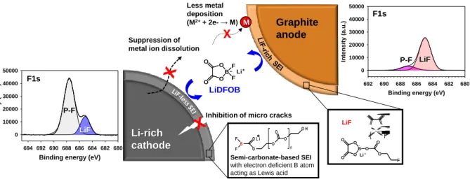
Electrochemical performance of Li-rich/graphite full cells at 25 oC: (a) voltage profiles during pre-cycle; and (b) retention of discharge capacity and Coulombic efficiency at a rate of C/2 over 200 cycles. Scheme of the proposed reaction mechanism of LiDFOB on Li-rich cathode and graphite anode.
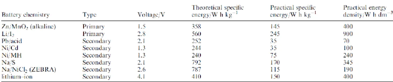
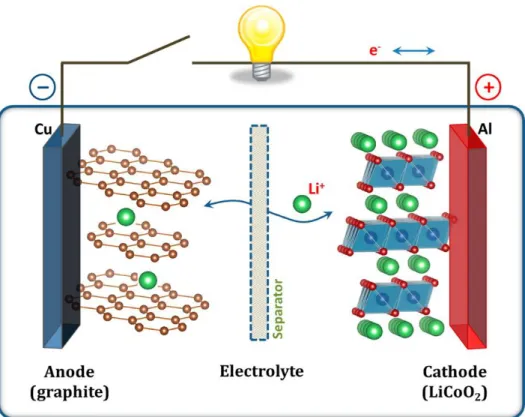
Lithium-ion battery
The specific capacity of the Li-rich cathode for a full cell connected to a graphite anode was 1.442 mAh cm-2. Another noticeable feature is that the voltage drop of the Li-rich cathode is mitigated with LiDFOB during the pre-cycle discharge process. The LiDFOB-derived surface film (i.e., the SEI) is thought to be less resistive compared to the baseline electrolyte-derived SEI thereby allowing easy relithiation of the Li-rich cathode.
12 shows the surface chemistry of Li-rich cathodes with and without 1% LiDFOB after precycling. It is likely that the salt-type LiDFOB additive forms the desirable SEI on the graphite anode and Li-rich cathode in the full cell. Additionally, the LiDFOB-derived SEI sufficiently attenuates the dissolution of metal ions from the Li-rich cathode, resulting in the inhibition of metal deposition on the graphite anode.
The introduction of LiDFOB shows a substantial improvement in the cycling performance of a high-voltage Li-rich cathode coupled to a graphite anode. Understanding the origin of Li2MnO3 activation in Li-rich cathode materials for lithium-ion batteries.
Li-rich layered cathode materials
Introduction
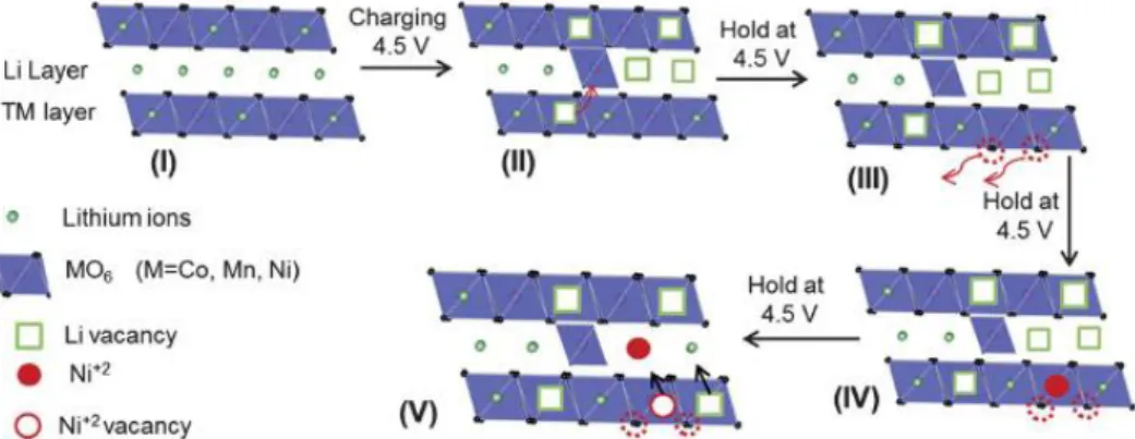
The structure of Li-rich layered material derived from the LiMO2 (M= transition metal) layered structure by replacing excess lithium in the MO2 layers (Fig. Li-rich cathode is generally represented by the formula xLi2MnO3∙(1-x) LiMO2 (M= Mn, Co, Ni…).6, 7 The Li-rich cathode materials have a larger capacity more than 200mAh g-1 with a high voltage plateau of ~4.5 V. The initial plateau region corresponds to the oxidation of LiMO2 structure and the oxidation of Li2MnO3 do not occur in this region.
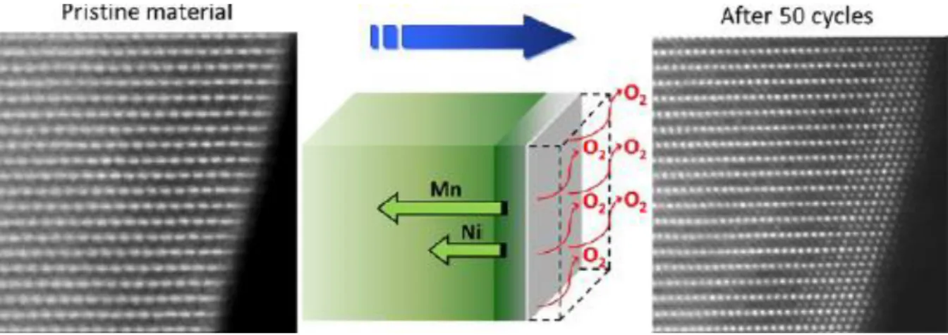
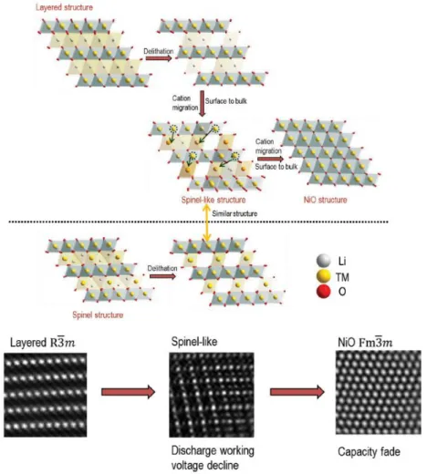
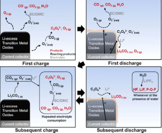
The electrochemical activation of Li2MnO3 corresponds to second plateau at the high voltage (~ 4.5 V) due to high oxidation state of Mn4+.8-10 However, the initial discharge has extreme irreversible capacity due to disadvantages of Li-rich cathode materials. During first charge and discharge, the large irreversible capacity of Li-rich layered cathode occurs in the oxygen release resulting from the activation of the Li2MnO3 at the 4.5 V plateau.
Challenges
Schematic of the evolution of oxygen as a result of migration of transition metal from the surface to the main mass. 13.
Improvement strategies
The research on LiDFOB
EXPERIMENTAL
Electrochemical measurements
Instrumental analysis
For the surface chemistry and morphological analyzes of the Li-rich cathodes and graphite anodes, the cells with and without LiDFOB were carefully disassembled in a glove box. The surface chemistry of the electrodes was investigated by ex situ X-ray photoelectron spectroscopy (XPS, Scientific K-Alpha system, Thermo Scientific) with Al Kα radiation (hν = 1486.6 eV) under ultrahigh vacuum. All XPS spectra were energy-calibrated by the hydrocarbon peak at a binding energy of 284.7 eV.
The surface morphologies of the electrodes were observed by field emission scanning electron microscopy (FE-SEM, JSM-6700F, JEOL) in a high vacuum environment.
RESULTS AND DISCUSSION
- Surface chemistry and morphology of the Li 1.17 Ni 0.17 Mn 0.5 Co 0.17 O 2 half cell
- Electrochemical performances of LiDFOB on the graphite anode half cell
- Surface chemistry and morphology of the graphite half cell
- Electrochemical performances of LiDFOB on the Li 1.17 Ni 0.17 Mn 0.5 Co 0.17 O 2 /graphite full cell.38
In order to investigate the effect of LiDFOB-derived SEI on the anodic stability of the electrolyte at high voltages, the potentiostatic profiles for Li/Li-rich cathode half-cells with and without 1% LiDFOB at constant voltage (4.9 V) are compared interestingly, introducing 1% LiDFOB leads to superior cycling stability of the Li-rich cathode, which retains 81.4% of the initial discharge capacity after the 200th cycle. In order to determine the origin of the sudden decrease in the capacity of the Li-rich cathode in the base electrolyte at the 70th cycle, the morphological changes of the cathodes were investigated (Fig.
However, in the baseline electrolyte, severe microcracking of the Li-rich particles is observed after the 140th cycle, as shown in Fig. This finding reveals that the baseline electrolyte is unable to produce a robust SEI layer that can prevent interfacial breakdown of high-voltage Li-rich cathodes. A comparison of the C 1s XPS spectra for the Li-rich cathodes clearly shows that the peak intensity attributed to semicarbonate-like species (-CO2-) at 289.1 eV relatively increases for the Li-rich cathode with 1% LiDFOB (Fig.
To confirm the compatibility of the LiDFOB additive with graphite anodes, the electrochemical performance of Li/graphite anode half-cells was investigated, as shown in Figure. The graphite anode with 1% LiDFOB exhibits higher charge plateaus (Li intercalation) and lower discharge plateaus. , indicating relatively low polarization compared to that of the baseline electrolyte (Fig. 13). It is believed that the EC solvent participates in the decomposition reaction pathway of LiDFOB and changes the surface chemistry of the graphite anode. dQ/dV plots of Li/graphite anode half-cells at 25 oC.
The positive impact of the LiDFOB-derived SEI on the cycling performance of the graphite anodes is depicted in Fig. Although the use of LiDFOB additive drastically improved the cycle performance of the graphite anode with EC-free electrolyte (EMC/DMC/1.3 M LiPF6) This excellent rate capability of the graphite anode is attributed to the LiDFOB-derived SEI that can facilitate Li- ion transport at the anode-electrolyte interface.
The highly improved performance of the graphite anode obtained with the addition of LiDFOB can be explained by the reduced relative amounts of metastable products (LixPFy, LixPOFy, P-O) generated by the decomposition of LiPF6 and the appearance of polar moieties (-CO2-) in the SEI created in the presence of LiDFOB (Fig. To understand the significant performance degradation of the Li/graphite-rich full cell with base electrolyte after 70 cycles, the graphite anodes obtained from these cells after 200 cycles were analyzed by SEM and EDS. To verify the effect of SEI, derived from LiDFOB, to the dissolution of metal ions from Li-rich cathodes, ICP-MS analysis was performed for fully delithiated cathodes with SEIs derived from baseline or LiDFOB.
19, the extent of dissolution of metal ions (Co, Mn and Ni) from a fully delithiated cathode after 24 h at 60 °C is drastically reduced by the presence of SEI derived from LiDFOB on the cathode surface. A comparison of the dissolution of transition metals (Co, Mn, Ni) from fully delithiated Li-rich cathodes with the SEI layer resulting from the decomposition of base electrolyte or 1% added electrolyte in LiDFOB at 60 oC for 24 h.
CONCLUSION
Review-Lithium-rich layered oxide cathodes for next-generation Li-ion batteries: opportunities and challenges. Recent advances in electrolytes for interfacial stability of high-voltage cathodes in lithium-ion batteries. First evidence of cycling segregation and densification of manganese and nickel in layered Li-rich oxides for lithium batteries.
Lithium difluoro(bisoxalate) phosphate-derived intermediate architectures for lithium-rich cathodes with superior cycling stability and rate. Tunable and robust phosphite-derived surface film for protection of lithium-rich cathodes in lithium-ion batteries, ACS Appl. Tris (2,2,2-trifluoroethyl) phosphite as an electrolyte additive for high-voltage lithium-ion batteries using a layered lithium-rich oxide cathode.
Triphenyl phosphite as electrolyte additive to improve the cyclic stability of lithium-rich layered oxide cathode for lithium-ion batteries. Counterintuitive role of magnesium salts as effective electrolyte additives for high-voltage lithium-ion batteries. Synergistic effect between lithium bis(fluorosulfonyl)imide (LiFSI) and lithium bis-oxalatoborate (LiBOB) salts in LiPF6-based electrolyte for high-performance Li-ion batteries.
Investigation of lithium tetrafluoro-oxalatophosphate (LiPF4(C2O4)) as a lithium-ion battery electrolyte for elevated temperature performance. Investigation and application of lithium difluoro(oxalate)borate (LiDFOB) as additive to improve the thermal stability of electrolyte for lithium ion batteries. Effect of lithium difluoro(oxalate)borate (LiDFOB) additive on the performance of high voltage lithium ion batteries.
Understanding the incremental capacity enhancement of high-energy-low-Co Li-rich cathode materials for lithium-ion batteries. Intragranular cracking as a critical barrier for high-voltage use of layer-structured cathode for lithium-ion batteries. A bifunctional lithium difluoro(oxalato)borate additive for lithium cobalt oxide/lithium nickel manganese cobalt oxide cathodes and silicon/graphite anodes in lithium ion batteries at elevated temperatures.