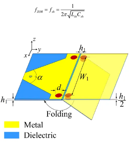
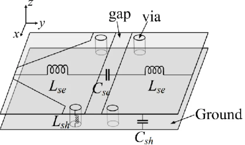
Then the excellent candidate of ZOR antenna is chosen for the actual body experiment to evaluate the feasibility. The proposed ZOR antenna has two faces with a tapered portion and a rectangular face separated by an opening, and those faces are connected via vias at two corners near the opening. Two identical antennas are fabricated on a flexible printed circuit board (FPCB) and the zero-order resonance properties are compared with those of the fundamental mode to demonstrate feasibility.
The zero-order resonance of the proposed antenna exhibits a negligible frequency shift and its quality factor is 2.9 times higher than the fundamental mode when coupled to the skin. The results show that the proposed concept has great potential to improve the accuracy of non-invasive estimation in the microwave spectrum. The proposed antenna has a radiating area from 2.35 GHz to 2.65 GHz in accordance with the continuous back-to-front scanning angle without open stopband.
The wide steering angle shows a promising approach to keep verifying the characteristics of the antenna in the change of the glucose level.
INTRODUCTION
Literature Review
- Diabetes: Definition, Classification, Current Treatment Method
- Glucose monitoring methods
This method is one of the most accurate, but it remains some disadvantages such as human pain, infection, time consumption, high cost and discrete measurement times. In [11], a pair of slot antennas operating in the ultra-wideband is proposed to observe the regularity change by observing the human earlobe phantom, and the hexagonal-shaped complementary split-ring resonator is presented in [12] to observe both the phase take and size of the transmission coefficient according to different levels of the glucose sample. The resonant perturbation method is a subset of the reflection and transmission methods and is also known as a fringe field method [13]–.
Unlike other approaches, this method uses narrowband antennas with a quality factor (Q) to measure resonant frequency changes related to the dielectric properties of the medium. Other examples of microwave-based sensors can be antenna dielectric resonators [16], split-ring resonators, and a coplanar transmission line loaded with an LC resonator [19].
Fundamentals of CRLH TL Metamaterials
- Metamaterials
- CRLH TL Metamaterials
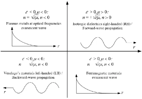
In [13], a rectangular waveguide cavity with the fundamental resonant mode is presented, which exhibits a shift of resonant frequency and reduction of the Q-factor. Whereas the three combinations are well known in conventional materials (plasma metals at optical frequencies . and ), the one with simultaneous negative permittivity and permeability corresponds to the new class of metamaterials called left-handed materials. As a result, the electromagnetic waves travel in the opposite direction of the energy flow, which is known as the backward waves.
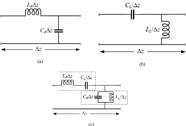
The conventional TL was analyzed by the distribution of series inductance (Lse) and shunt capacitance (Csh), known as right-handed materials (RHM), shown in Fig. (Cse) and shunt inductance (Lsh) by Brillouin and Pierce in the 1940s, shown in Fig. It is known that a PLH structure does not physically exist due to the parasitic series inductance and shunt capacitance effects of current flow in metallizations and voltage gradients between the metal patterns respectively.
The CRLH metamaterial, which consists of both right-handed (RH) and left-handed (LH) properties was introduced by C.Caloz, the corresponding circuit model of the ideal CRLH TL is shown in Fig. It is composed of a per unit length impedance Z′ (.m) is made up of a RH per unit-length inductance LR (H/m) in series with a LH times unit-length capacitance CL (F.m) and a per-length admittance Y′ (S/m) is constituted by a RH per-length capacitance CR (F /m) in parallel with a LH times unit-length inductance LL (H.m). In general, the series and shunt resonances of CRLH TL are different, which is called the unbalanced case.
At low frequencies, LR and CR tend to be shorted and open, so the equivalent circuit is reduced to LL and CL; while at high frequencies LL and CL are short and open to the remaining LR and CR. The unique properties of CRLH TL are used in a wide range of microwave guided wave and radiated wave applications. In our interest, we used these new properties to implement biosensors operating in the medical frequency band through the two concepts of a zero-order resonator and a leaky-wave antenna.
DESIGN OF ZEROTH-ORDER RESONANCE ANTENNA
- Design approach
- Parametric study
- Fabrication and measurement
- Experiment of non-invasive glucose monitoring
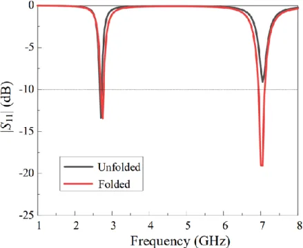
Ansys High-Frequency Structure Simulator (HFSS) is used to analyze the antenna properties, and the simulated reflection coefficients for the folded and unfolded configurations are compared in Fig. To analyze the effect of the tapered section, variations of the steering angle θsteer and front-to-back ratio (FBR) are calculated according to α, as shown in fig. The conventional antenna is designed to resonate at 2.75 GHz as a fundamental mode and the same material properties of the FPCB are used.
Coupling strength changes |S21| then they are studied for different relative permittivity εr of the fatty layer. Coupling strength variations in dB with respect to the permittivity of the fat layer at different frequencies. Variations of |S21| at 2.5 GHz for the four orientations regarding the allowability of the fat layer.
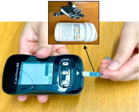
This means that ZOR is more robust to high-dielectric, high-loss skin condition in terms of frequency shift, quality factor, and impedance matching properties. The center of the antenna is located at the origin of the rectangular coordinates, and the longer edge of the antenna is parallel to the x-axis. In this experiment, two antennas are attached to the lower extremity of a non-diabetic person to track coupling power at 2.454 GHz, the frequency of peak coupling power after fasting.
During the first 20 minutes, the subject was allowed to rest to confirm initial levels of coupling strength and glucose concentration. Note that the two studies have different mean levels of |S21| and the glucose concentration because these measurement data are very sensitive to the conditions of the subject and the time of the experiment. The two studies show that the total changes in glucose concentration are 116 mg/dl and 87 mg/dl, which are related to the |S21| variations of 0.92 dB and 1.01 dB, respectively.
Measured |S21| obtained from (a) the vector network analyzer and (b) the printed circuit board as a function of glucose concentration. The robustness of the proposed approach against the high dielectric and lossy conditions of the human tissues is determined by the amount of unwanted frequency shifts between the free space and the skin attachment.
DESIGN OF LEAKY-WAVE ANTENNA
The proposed Leaky-wave Antenna
To obtain sufficient capacitance for the CRLH TL equilibrium state, the number of slots is considered. The propagation characteristic of the proposed unit cell is investigated by the dispersion diagram shown in the figure. The entire frequency range is divided into three areas by the ratio between the propagation constant and k0.
On the other hand, the wave can radiate in the fast wave region ( > k0) called the leakage region with a frequency range of 2.35 GHz to 2.68 GHz. In the fast wave region, the transition frequency separating the LH and RH regions is at 2.5 GHz. The wave radiates back in the LH range and scans forward in the RH frequency range, broadside radiation is obtained at the transition frequency.
The entire final LWA structure is implemented by calculating the Bloch impedance from the unit cell to achieve good impedance matching. The concept of Bloch impedance is used in the CRLH TL structure to indicate the relationship between voltages and currents in the network. It can be considered as the characteristic impedance of a transmission line in the case of a discontinuous network.
Real and imaginary part of the Bloch impedance for the proposed unit cell as a function of frequency. For the impedance matching, the tapered line is used to convert the 50 microstrip lines to 65 by calculating the appropriate width. The length lt and the width wt and wm of the tapered portion are optimized to 16 mm, 0.5 mm and 3 mm, respectively.

Simulation Results
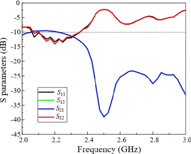
The simulated S-parameters of the full-length structure of our proposed LWA are given in Fig. It is clear to see that the scan angle range is quite symmetrical, consistent with the symmetry of the dispersion diagram. It can be explained by the fact that the configuration of unit cell simulation is infinite, but the realized length of the antenna is limited.
Furthermore, the feasibility of the proposed antenna was proven by comparing it with the conventional patch antenna having fundamental mode resonance. The results showed that the proposed ZOR antenna is suitable for more accurate estimation in non-invasive CGM systems as a replacement of the conventional patch antenna with fundamental mode resonance. Mobashsher and C. Abbosh, "The Progress of Glucose Monitoring - A Review of Invasive to Minimally and Non-Invasive Techniques, Devices and Sensors", Sensors, vol.
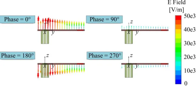
As shown in Fig. 1(a), due to the Floquet–Bloch theorem, multiple diffraction modes will appear when the incident waves strike the periodic metasurfaces. The synthesis gives the idea that the assumption of surface waves with decreasing power in the +z-direction on the upper side of the metasurface matches the local power profile without affecting the overall function of the metasurface. The first step in designing an O-BMS is to determine the two electromagnetic fields at the top and bottom of the metasurface.
1(b), the equation for the fields in both the top and bottom facets of the metasurface can be defined as follows: jkz jky in jkz jky in. 3) (4) where the amplitudes of the incident and reflected waves are indicated as Ein and Eout respectively. The bianisotropic skin transition states show that the bianisotropic metasurface constituents can be resolved when specifying the fields in the top and bottom facets of the metasurface.
While the first case shows the electric fields that can reflect normal incident waves 70, the two cases below show the oblique incident waves with the angle of incidence of 40 and 60 towards normal reflection. The size of the unit cell can be calculated and then divided by the number of unit cells per supercell, known as λ0/5.