However, notorious reactivity at the cathode/anode interfaces and volatile and flammable properties of the conventional electrolyte hinder the implementation of the LMBs for the large-scale application such as electric vehicles. One of the promising ways to address these issues is the rational design of the non-flammable electrolyte with high stability against the electrodes. By improving the lithium/electrolyte interface stability by modifying the coordination and alloy chemistry, we successfully demonstrated 4.4 V Li||NCM 811 and 4.9 V Li||LNMO cells for 100 cycles.
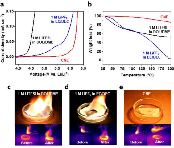
In particular, the reversible charge/discharge at 100ºC and operation even in the flame above 800ºC of the 4.9 V Li||LNMO cell prove the exceptional thermal stability of nitrile electrolyte, suggesting a direction for the next generation of electrolyte for advanced batteries. Oxidation and thermal stability of electrolytes. a) LSV spectra of electrolytes, (b) TGA curves of electrolytes, (c) Flammability tests of electrolyte. Improving the reduction stability of nitrile electrolytes. a) Schematic representation of nitrile polymerization, (b) solvent infiltration using CNE and (c) alloy composite layer derived from CNE + LiNO3/InF3.
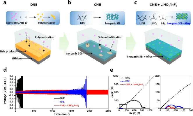
EIS spectra of symmetric Li||Li cells using CNE with additives (LiNO3, InF3 and LiNO3/InF3). a) Coulombic efficiency of asymmetric Li||Cu cells using DNE, CNE and CNE+LiNO3/InF3. SEM images of lithium (a, c and e) and atomic ratio of SEI components (b, d and f) in lithium after 20 cycles of the symmetric Li||Li cell in a. In depth TOF-SIMS spectra of lithium for 200 s (c, and f). g) Three-dimensional distribution of SEI inorganic component (LiF+) and alloy composition (In+) in lithium cycled with CNE + LiNO3/InF3.
In-depth TOF-SIMS spectra of LiF– and MnF3–. Morphology of lithium cycled with carbonate electrolyte.
Introduction ·
Requirements of electrolytes for lithium metal batteries
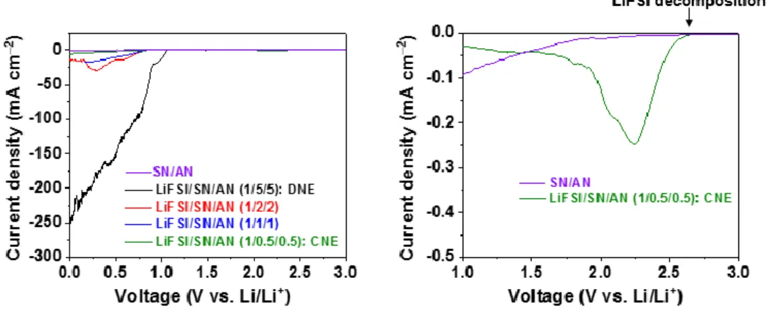
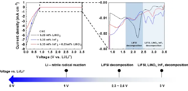
The aggressive environment originating from the highly reactive lithium metal anode and catalytic high-voltage cathode can cause severe electrolyte degradation, resulting in electrolyte depletion and performance reduction. To suppress the side reaction at the interfaces, the electrochemical potential window of the electrolytes must be wide enough to withstand the harsh conditions. In addition to the electrochemical/chemical stability against the electrodes, the safety of LMBs must be taken seriously.
As dendritic growth of lithium frequently occurs during charge/discharge process, it potentially causes internet short circuit, exposing LMBs to potential explosion. Electrolyte must possess nonflammability at elevated temperature and form stable SEI on the lithium to suppress the dendritic growth of the lithium.
Nonflammable Nitrile-Based Electrolytes for High-Voltage Lithium Metal
Experimental
- Characterization of electrolytes
- Electrochemical measurements
- Characterization of lithium/cathode
- Safety tests
The ionic conductivity of the electrolyte was measured using a button cell with EIS in the range from 10 mHz to 1 MHz. Raman spectra of the nitrile-based electrolyte at different concentrations were obtained with a confocal Raman microscope (Alpha 300R) at a wavelength of 532 nm. Thermogravimetric tests (TGA) (Q500, TA) were performed to measure the weight loss of the electrolyte at elevated temperature.
For linear sweep voltammetry (LSV), cyclic voltammetry (CV) and electrochemical impedance spectroscopy (EIS) the VMP3 potentiostat (Biological) was used. Platinum (Pt) rod (Diameter 0.6 mm) and Cu foil were used as working electrode for oxidation and reduction stability test, respectively. Impedance was measured in the range of 10 mHz to 1 MHz with an AC potential amplitude of 10 mV.
All galvanostatic cycling tests were performed using a battery test device (PNE Solution) at room temperature. Symmetrical Li Cell Tests To estimate the coulombic efficiency, lithium was removed until the cell potential became 1 V vs.
Scanning electron microscopy (SEM) (S-4800, Hitachi) was used to analyze the morphology of the deposited lithium. For the transmission electron microscope (TEM) analysis, samples were prepared with an argon ion grinding system (Model 1040 Nanomill, Fischione). High-resolution transmission electron microscopy (HR-TEM) (JEM-2100F, JEOL) was used to characterize the thickness of the CEI layer.
Time-of-flight secondary-ion mass spectroscopy (TOF-SIMS) (TOF-SIMS 5, Ion TOF) was used to analyze the component on the lithium and the NCM 811 with a Bi32+ gun at 25 keV. To verify the non-flammability of the electrolytes, separators (celgard 3501) were impregnated with various electrolytes and gas torched onto the glass petri dish. To evaluate the safety of the cell under high temperature (100ºC), 4.9 V charged LNMO cell was put in the oven and OCV of the cells was recorded for 1 hour.
Results and discussion
- Oxidation and thermal stability of electrolytes
- Reduction stability enhancement of nitrile electrolytes
- Morphology and SEI compositions of lithium
- Characterization of lithium
- Li||NCM 811 cells and cathode stabilization
- Safety of Li||LNMO cells
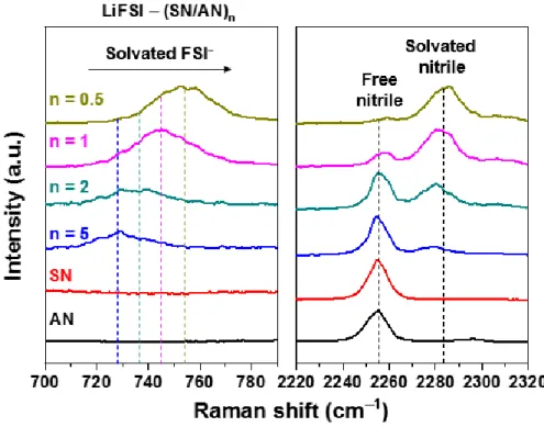
Raman spectra clearly evidence the reduced fraction of the free nitrile in the CNE (Figure 2.6). Although this by-product was not observed in the lithium circled with the CNE, dendritic growth of the lithium was observed on the lithium, implying limitation of salt-concentrated electrolyte strategies for the nitrile-based electrolyte (Figure 2.11 c). To reveal the unusually even morphology of the lithium, atomic ratio Figure 2.10. a) Coulombic efficiency of Li||Cu asymmetric cells using DNE, CNE and CNE+LiNO3/InF3.
In particular, the proportion of element F in CNE + LiNO3/InF3 was always higher than in CNE, which means that LiNO3 and InF3 beneficially contributed to the formation of the F-based inorganic component (LiF) (Figure 2.11 d and f). The intensity of LiF for CNE and CNE+LiNO3/InF3 increased after sputtering for 5 and 10 min, indicating that LiF formed in the SEI inner layer. As shown in Figure 2.12 c, the intensity of LiF+ was only detected for 100 seconds in CNE-cycled Li.
The Li||NCM 811 cell with CNE + LiNO3/InF3 showed the best cycling stability, retaining 86% of reversible capacity after 120 cycles, compared to the cell cycled with DNE (3 cycles, 0% capacity retention) and even 1M LiPF6 carbonate electrolyte in EC/DEC (76 cycles, 80% capacity retention). To reveal the superior cycle performance of the cell with CNE + LiNO3/InF3, comprehensive understanding at the cathode and anode were simultaneously pursued. As a result of the side reaction, the irreversible capacity of the NCM 811 cell cycled with DNE increased continuously and severe capacity decay was observed within 3 cycles (Figure 2.14).
The layered structure of the R3̅m space group was observed in the inner phase of both samples. Moreover, high cut-off voltage (4.4 V) can accelerate microcracks and electrolyte decomposition [16, 34]. These explain that the interfacial stability between NCM 811 and nitrile-based electrolyte at the high voltage (4.4 V) hinders the deterioration of the crystalline structure.
The superior cycle performance of the cell cycled with CNE+LiNO3/InF3 was supported by time-of-flight secondary ion mass spectroscopy (TOF-SIMS) analysis with depth profiling on NCM 811. In addition, previous studies reported that dissolved manganese ion could induce dendritic growth of lithium. In addition, the rate performance of the Li||LNMO cell was evaluated to verify the fast transport of CNE + LiNO3/InF3 ions at different C levels from 0.2 C to 5 C.
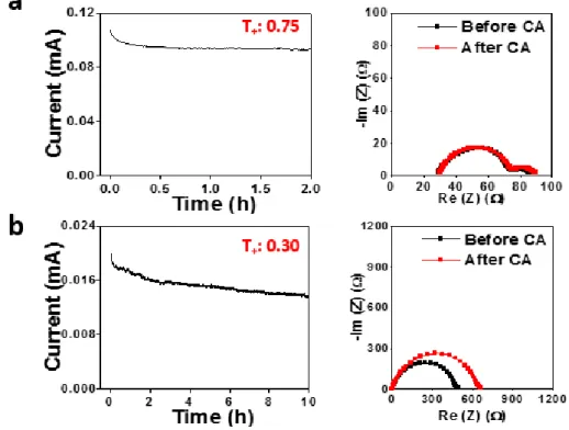
To further investigate the thermal stability of the Li||LNMO cell, a hot box test at 100 °C was performed. The open circuit voltage (OCV) of the 4.9 V charged cell was recorded as a function of time at 100 °C. In contrast to charging the cell with 1 M LiPF6 in EC/DEC, the cell voltage with CNE+LiNO3/InF3 did not drop below 4.7 V for 1 hour without self-discharge.
In particular, the safety tolerance of the 4.9 V charged Li||LNMO cell was evaluated in abuse mode.
Conclusion
![Figure 1.1. Ragone plot of rechargeable batteries. Reproduced from ref [1]. Copyright 2018 IEEE](https://thumb-ap.123doks.com/thumbv2/123dokinfo/10496880.0/13.892.188.711.440.815/figure-ragone-plot-rechargeable-batteries-reproduced-copyright-ieee.webp)