G ENERAL I NTRODUCTION
E LECTROCATALYSTS FOR OXYGEN REDUCTION REACTION
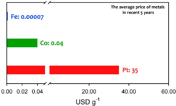
- Precious-Metals Based Electrocatalysts
- H e t e r o at om - D o pe d Car b on an d No n - Pr ec i ou s M et al - B as e d
- Challenge: Low Activity of Non-Precious Metal-Based Electrocatalysts
Large amounts of Pt-based catalysts are usually used in the PEFC cathode to avoid slow ORR kinetics. The n values of doped OMCs are strongly linearly related to their work function (Figure 1.9d).
M–N/C E LECTROCATALYSTS
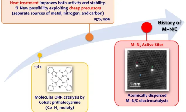
- Introduction to M–N/C Electrocatalysts
- Preparation of M–N/C Electrocatalysts
- Recent Advances in Synthetic Strategies for M–N/C Electrocatalysts
These results suggest that the high micropore content of the carbon supports in Fe–N/C catalysts is a key to host the Fe–Nx active sites. a) Fe−Nx active site structure expected in Fe−N/C catalysts. From these results, it was found that the origin of the catalytic activity of Fe−N/C catalysts is distorted Fe−Nx sites.
O UTLINE OF T HIS D ISSERTATION
R EFERENCES
The four-electron selectivity of the Fe-Phen/CNT_X wt% catalysts showed similar trends with the ORR activity. The Fe–Nx@SBA-15 composite is obtained after pyrolysis at 800 °C of the Fe-Phen_1.0 precursor mixture.
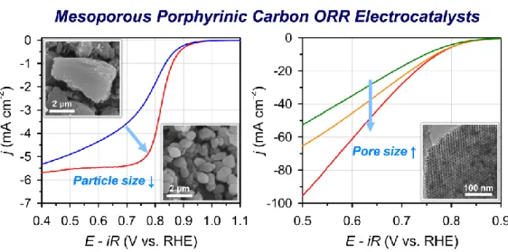
I MPACT OF T EXTURAL P ROPERTIES OF M ESOPOROUS P ORPHYRINIC C ARBON
E XPERIMENTAL M ETHODS
- Synthesis of Mesoporous Silica Templates
- Synthesis of Fe-MPC Catalysts
- Characterization Methods
- Electrochemical Characterizations
Each part of the mixture was then subjected to a hydrothermal treatment at a desired temperature (35, 100 or 150 °C) for 24 h. The textural properties of the samples were analyzed using a nitrogen physisorption analyzer (BELSORP-Max, BEL JAPAN, Inc.) operated at −196 °C.
R ESULTS AND D ISCUSSION
- Synthesis Optimization of Fe-MPC Catalysts
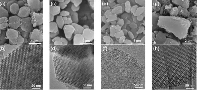
- Physicochemical Characterizations
- ORR Activity on the Rotating Ring-Disk Electrode and Carbon Paper
- Impact of Textural Properties of Fe–N/C Catalysts on ORR Activity
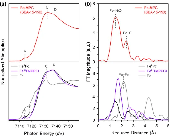
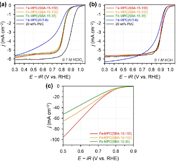
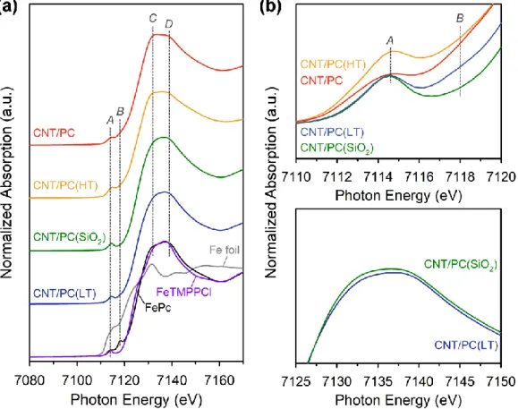
Finally, to understand the origin of the excellent ORR activities of Fe-MPC(SBA-15-X), the local structure around the Fe atoms was investigated by X-ray absorption spectroscopy (XAS). The main difference between the XANES spectrum for Fe-MPC(SBA-15-150) and the spectra for FeIIITMPCCl and FeIIPc is the relative intensity of the XANES signals at 7132 eV and 7140 eV (peaks C and D, respectively). The ORR activity of Fe-MPC(KIT-6) was lower than that of Fe-MPC(SBA-15-X), but it still remains a high half-wave potential activity.
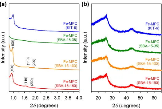
The ORR activities of Fe-MPC(SBA-15-X) catalysts are among the best reported for Fe-N/C catalysts. Elemental analyzes of Fe-MPC (SBA-15-X) catalysts by inductively coupled plasma optical emission spectrometry (ICP-OES) as well as combustion analysis suggested that all three Fe-MPC (SBA-15- X) have similar Fe and N contents.
C ONCLUSION
R EFERENCES
I NTRODUCTION
The design of Fe-N/C catalysts with abundant active sites has been actively pursued based on an understanding of the active sites in Fe-N/C catalysts. It was suggested that the silica layer would retain Fe-N4 sites in the iron porphyrin precursor through axial direction bonding between Fe and O, thus preventing the aggregation of Fe particles during pyrolysis. The resulting Fe-N/C catalyst contained a higher density of Fe-Nx sites compared to the catalyst prepared without the silica coating step, and therefore showed better ORR activity in both alkaline and acidic media.
In the present work, we demonstrate the general applicability of the silica-coating-mediated synthetic strategy using a variety of precursors (Fe-porphyrin, Fe(II)-acetate/1,10-phenanthroline and Fe(III)-chloride/polyaniline) in the formation of highly active Fe–N/C catalysts with abundant Fe–Nx. Furthermore, the impact of Fe contents in the precursor mixture and pyrolysis temperatures on the ORR activity of Fe–N/C catalysts was investigated.
E XPERIMENTAL M ETHODS
- Synthesis of Fe–N/C Catalysts with Silica Protective Layer
- Characterization Methods
- Electrochemical Characterizations
- AEMFC Performance Tests
- PEMFC Performance Tests
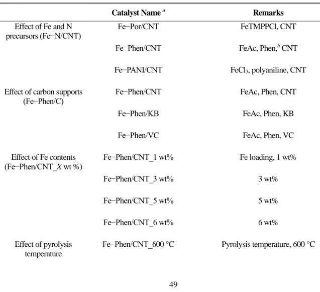
The samples prepared without the silica coating were designated as Fe-Phen/C_w/o SiO2 (C = CNT, KB or VC) catalysts. The resulting catalysts are denoted Fe-Phen/CNT_X wt.%. X: nominal iron content in the precursor mixture and 6), and the counterparts prepared without the silica coating step were designated as Fe-Phen/CNT_X wt%_w/o SiO2. The resulting catalysts were designated by Fe-Phen/CNT_Y °C (Y: pyrolysis temperature), and the counterparts prepared without the silica coating step were designated by Fe-Phen/CNT_Y °C_w/o SiO2.
Another series of S-doped and P-doped Fe-Phen/CNT catalysts (Fe-S-Phen/CNT_2 and Fe-P-Phen/CNT_2) were prepared using diphenyl disulfide and tris(diethylamino)phosphine as the S- and P sources. respectively. The subsequent steps after mixing the precursor were the same as those used for the optimized Fe-Phen/CNT catalyst described above.
R ESULTS AND D ISCUSSION
- Effect of Fe and N Precursors
- Effect of Carbon Support Types
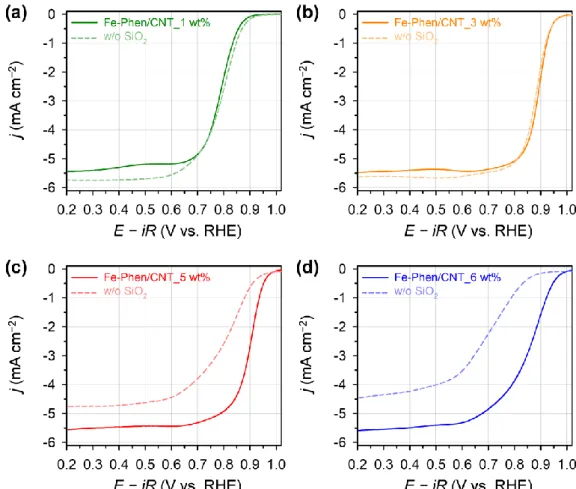
- Effect of Fe Contents
- Effect of Pyrolysis Temperature
- Effect of Additional Heteroatom Doping
- Single Cell Performance
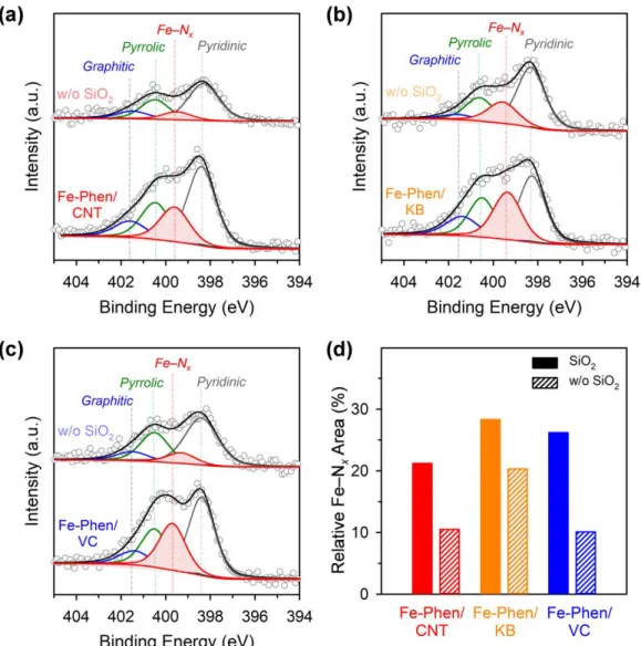
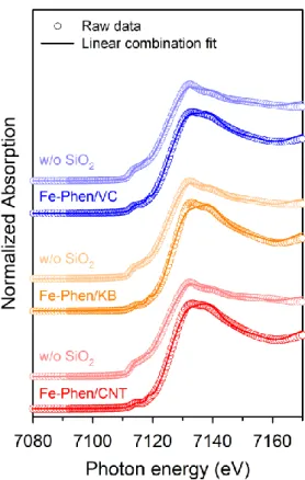
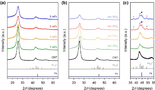
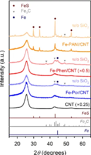
Finally, we performed XRD and EXAFS analyzes of Fe-Phen/CNT and Fe-Phen/CNT_w/o SiO2. XRD patterns of the Fe−Phen/C and Fe−Phen/C_w/o SiO2 catalysts prepared with different carbon supports. Raw XANES data and LCF spectra of the Fe-Phen/C and Fe-Phen/C_w/o SiO2 catalysts.
Deconvoluted XPS N 1s spectra of Fe-Phen/CNT_Y °C catalysts pyrolyzed at 600 °C and 700 °C showed mainly pyridine N and Fe–Nx. When comparing the ORR activity of the three Fe-Phen/CNT-based catalysts, Fe-S-Phen/CNT and Fe-P-.
C ONCLUSION
R EFERENCES
Comparing the Fe species of CNT/PC and those synthesized without silica coating (CNT/PC_w/o SiO2), it was observed that the majority of Fe in CNT/PC was in the form of atomically dispersed Fe sites (91%), while CNT/PC_w/o SiO2 had significant Fe-based particles (55%). Fourier-transformed EXAFS spectra of CNT/PC intermediates, along with those of Fe (gray), FePc (black), and FeTMPPCl (purple) foil references. In the CNT/PC(HT) sample, Fe3C and α-Fe were observed and the content of superparamagnetic Fe increased by approximately three times compared to that of the CNT/PC(SiO2) sample (Table 4.3).
Consequently, the CNT/PC with the silica coating had a density of Fe-Nx sites twice as high as that of the CNT/PC_w/o SiO2. The experimental evidence suggested that the stacked Fe-Nx sites were responsible for the higher ORR activity of the rod-structured Fe-Phen_2.0.
E XPERIMENTAL M ETHODS
- Synthesis of 57 CNT/PC Catalysts
- Characterization Methods
- XAS Experiments
- Electrochemical Characterizations
- AEMFC Performances
Fe K-Edge XAS profiles were collected at RT in the 10C beam of the Pohang Accelerator Laboratory (PAL). The isomer shifts were calibrated relative to the center of the spectrum of an α-Fe foil at RT. During potential sweep the applied potential of the Pt ring was held at 1.3 V (vs. RHE) to measure the 4-electron selectivity.
The CCM thus prepared was soaked in 1 M NaOH for 12 h to improve the ionic conductivity of the membrane by replacing anions with OH– ions. The microporous GDL layer was placed facing the catalyst layers on the CCM.
R ESULTS AND D ISCUSSION
- Synthesis of 57 CNT/PC Catalysts
- XAS Analysis
- Physicochemical Characterizations
- Role of Fe–Si Interactions
Furthermore, the CNT/PC(LT) and CNT/PC(SiO2) samples showed similar relative intensity ratios of peaks C and D as the references. The HAADF-STEM images of CNT/PC(HT) and CNT/PC are shown in the inset. The Mӧssbauer spectrum of CNT/PC_w/o SiO2(HT) clearly showed a very pronounced singlet and two sextet peaks compared to that of CNT/PC(HT) (Figure 4.10e).
Furthermore, the kinetic current density at 0.9 V for the CNT/PC was twice higher than that of the CNT/PC_w/o SiO2 (Figure 4.12b). The improved alkaline ORR performance of the CNT/PC catalyst over the CNT/PC_w/o SiO2 sample can be mainly associated with the larger number of Fe–Nx sites.
C ONCLUSION
ORR performances of the catalysts from the RRDE test at a rotation speed of 1600 rpm and a scan rate of 5 mV s−1. The catalyst loading on the glassy carbon electrode was 0.8 mg cm−2. c) Alkaline AEMFC performance of MEAs using CNT/PC and Pt/C as cathode catalysts.
R EFERENCES
Fe-Phen_C catalyst is synthesized by mixing mesophase resin, Fe–Nx@SBA-15 composite and EtOH. As shown in Figure 5.1, Fe-Phen_X (X = mass ratio of Fe precursors, N and quartz template) is synthesized by dry mixing of Fe acetate (FeAc), Phen and mesoporous silica. The porous structures of Fe-Phen_X catalysts and silica templates were investigated by nitrogen adsorption-desorption analyzes (Figure 5.5 and Table 5.2).
Compiling the ICP and XAS results suggests that Fe-Phen_1.0 and Fe-Phen_2.0 have a similar amount of the same Fe-Nx active sites. Interestingly, the Fe-Phen_C_Fe, which has a carbon layer in the middle of the Fe-Nx layers, showed relatively lower ORR performance than Fe-Phen_2.0 (Figures 5.14c,d).
E XPERIMENTAL M ETHODS
- Synthesis of Fe-Phen_X Catalysts
- Characterization Methods
- XAS Experiments
- CO cryo Adsorption
- O 2 Temperature Programmed Desorption
- Electrochemical Characterizations
The synthesis of Fe-Phen_X (X = mass ratio of Fe, N precursors and silica template) was carried out by dry mixing of FeAc, Phen and mesoporous silica SBA-15. The HF etching process was repeated in the same way and the obtained sample was dried at 60 °C to obtain Fe-Phen_X samples. The resulting Carbon@Fe–Nx@SBA-15 composite was mixed with 1:1 (v/v)=EtOH:10% aqueous HF solution and the mixture was stirred for 30 minutes, filtered and washed several times with EtOH.
The HF etching process was repeated in the same way and the resulting sample was dried at 60 °C to provide the Fe-Phen_C sample. Fe-Phen_C_Fe catalyst (layer-by-layer catalyst) is synthesized through dry mixing of FeAc, Phen and Carbon@Fe–Nx@SBA-15 composite.
R ESULTS AND D ISCUSSION
- Synthesis of Fe-Phen_X Catalysts
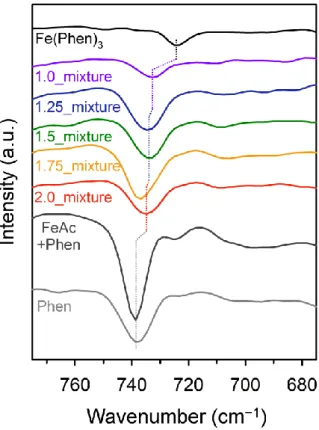
- Fe(Phen) 3 Complex Formation in Precursor Mixture
- Structural Difference between Fe-Phen_X Catalysts
- CO cryo Adsorption
- ORR Activity and O 2 Temperature Programmed Desorption
- Structure of the Active Sites for ORR
The region (675–775 cm−1) of FT-IR spectra for the precursor mixtures of the Fe-Phen_X samples. On the other hand, the Fe-Phen_2.0 showed only one isotherm in the relative pressure range of 0.45–0.65. The pore size distribution curve of Fe-Phen_2.0 indicates that Fe-Phen_2.0 has a mesopore of 4.8 nm.
The ORR electrocatalytic properties of Fe-Phen_1.0 and Fe-Phen_2.0 were studied using the rotating ring electrode (RRDE) technique in 0.1 M KOH and 0.1 M HClO4. Moreover, the ORR activity was slightly recovered after electroreduction in 0.5 M NaCl (70 mV and 10 mV in Fe-Phen_1.0 and Fe-Phen_2.0, respectively).
C ONCLUSION
We expected that Fe-Phen_2.0 with folded carbon layer has more biporphyrin-like sites (or bifacial sites) than Fe-Phen_1.0, which would promote O2 desorption and ORR in Fe-Phen_2.0. Insight into the stacking effect of Fe–Nx sites on ORR activity provides an important guideline for the design of highly active Fe–N/C electrocatalysts. Furthermore, this study may provide a design principle for the development of advanced electrocatalysts for other important reactions.
R EFERENCES
This dissertation presents the development of atomically dispersed Fe-N/C catalysts for the oxygen reduction reaction (ORR) and elucidates the structure and effects of their active sites. Using XAS and 57Fe Mӧssbauer spectroscopy, we revealed the role of the inorganic silica layer in the formation of atomically dispersed Fe-based species during the silica coating-mediated synthesis of Fe-N/C catalysts. The insight gained into the structural properties of Fe-N/C catalysts for enhanced ORR activity can be further extended into a design principle for the development of advanced electrocatalysts for other important reactions.
We suggest some future studies to understand more in-depth the catalytic properties of atomically dispersed Fe-N/C catalysts. Structural evolution of atomically dispersed Fe species in Fe-N/C catalysts studied by X-ray absorption and 57Fe Mӧssbauer spectroscopies".
S UMMARY AND S UGGESTIONS FOR F UTURE S TUDIES
S UGGESTIONS FOR F UTURE S TUDIES
R EFERENCES
학부 3학년부터 박사과정을 마칠 때까지 많은 도움을 주신 분들께 감사의 말씀을 전하고 싶습니다. 그리고 오랫동안 연구실에서 함께 일하면서 많은 도움과 응원을 해주신 연구실 동기들과 선후배들에게도 진심으로 감사드립니다. 저의 발표와 논문에 대해 많은 조언을 해주시고, 제가 힘들 때 응원해 주셔서 감사합니다.
모든 면에서 부족한 점이 많았을 때 많은 도움을 준 두산에게도 감사드립니다. 공부하는 동안 많은 도움을 준 친구 Otijo도 많은 도움을 주었습니다. 감사합니다.