Schematic illustration of the layered-to-spinel phase transformation in Li2MnO3 during the initial cycle and after the multiple cycles. Schematic illustrations of the change of particle structure with and without AlF3 coating during cycling. Discharge capacity retention and average voltage of MN7525 and MNC622 as a function of the number of cycles between 2.5 and 4.6V at 1C.
The change in the discharge capacity and retention of pristine and 3 wt% AlF3 coated sample as a function of the number of cycles. Fast Fourier transform pattern signal profiles of (b) surface site and (c) bulk site of AlF3-coated sample.
Introduction
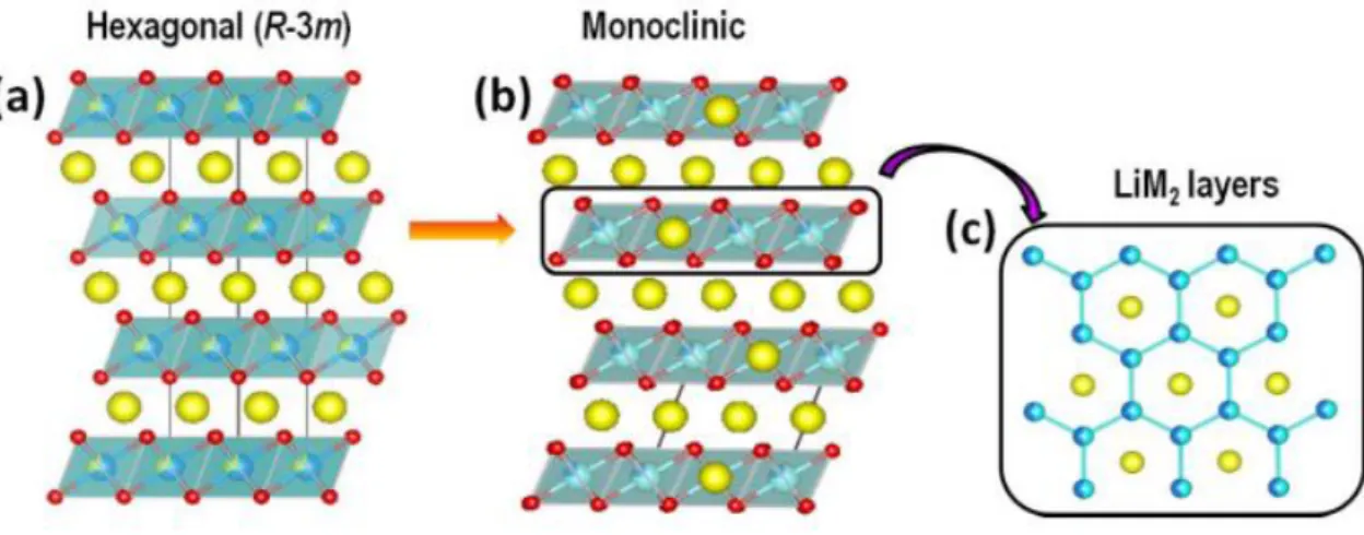
Co-free Li-, Mn- rich oxide (LMR) as a promising cathode materials
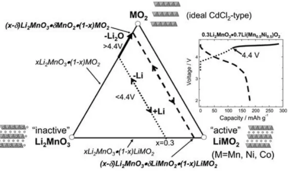
Li-, Mn-rich cathode (LMR), also called overlithiated oxide (OLO), has been in the spotlight for a long time as a promising cathode material due to its high theoretical capacity exceeding 250mAh/g. 21 Since lithium ions are present in the transition metal layers as well as in the lithium layers, more lithium ions can be utilized. Moreover, the presence of the Li2MnO3 phase and its activation process make more active sites for redox reactions.
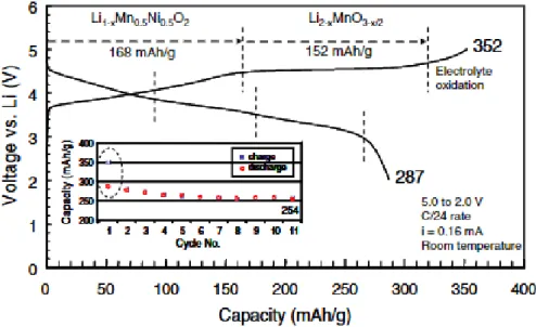
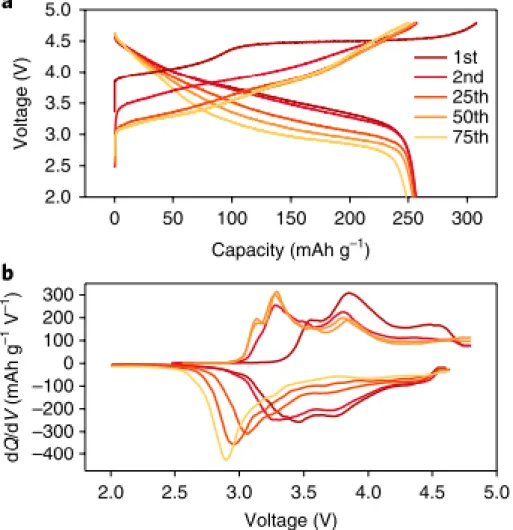
As shown in Figure 4, the extraction of lithium and oxygen ions arises from the Li2MnO3 phase during the initial charge, leading to a voltage plateau above 4.4 V. After the Li2MnO3 phase is activated, lithium ions can intercalate into the MnO2 structure and thus form LiMnO2, which is accompanied by the reduction of manganese.7.
Intrinsic problems of LMRs
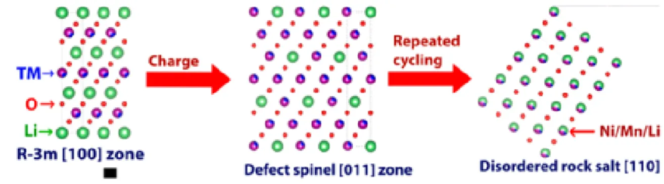
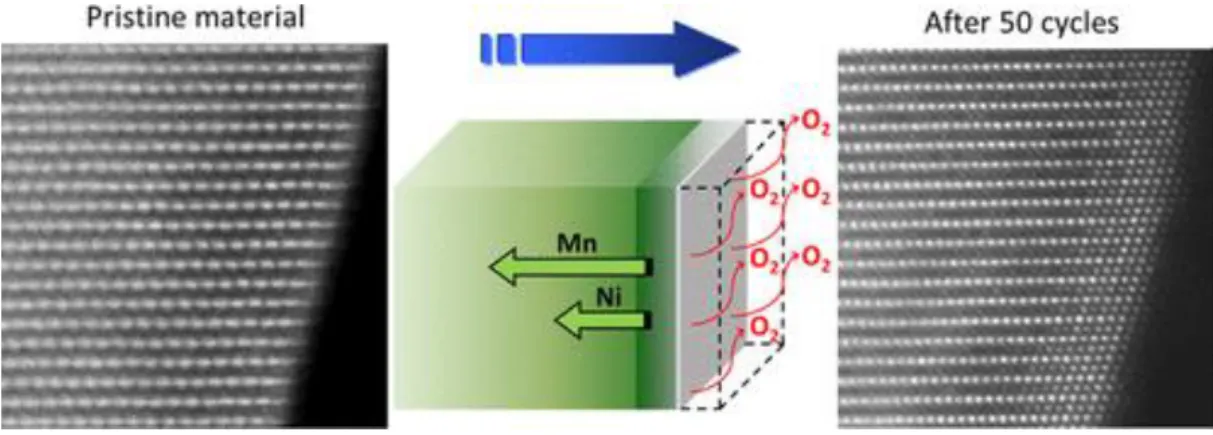
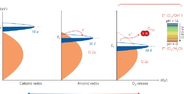
In fact, the theoretical capacity is higher than the calculated capacity of the cationic redox reaction. During the oxidation reaction, electrons are removed from the highest occupied molecular orbital (HOMO) level.25 When LMRs are delithiated during the first charge process, the HOMO level is e.g. the orbital of the dominant states of the transition metals. As a result, transition metals migrate into the Li layer without isolating the oxygen layer, generating Li-poor cubic spinel structure.
When lithium ions are reintroduced to the cathode after the first charge, most of the lithium ions intercalate into the Li layer. Schematic illustration of the transformation of the layered phase to spinel in Li2MnO3 during the initial cycle and after multiple cycles. 13.
Fundamental challenges of LMRs in practical perspectives
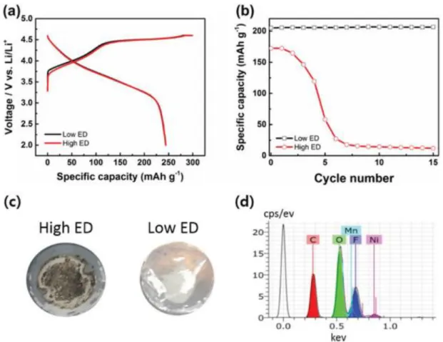
Electrochemical performance of LMR material with different electrode densities in the voltage range 2.0–4.6 V. a) Initial charge/discharge profiles at C/10. This voltage range is outside the electrochemical stability window of the electrolyte and accelerates electrolyte decomposition. Since the inner region of the particles is directly exposed to the electrolyte, severe morphological degradation occurs over a large area.29, 33, 34.
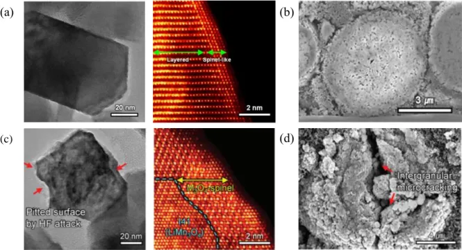
To make matters worse, in the case of LMRs, microstructural defects form more easily due to oxygen extraction during the initial cycles. Non-cycle LMR cathode has layered structure, except for the spinel-like phase in a narrow area of the surface. The surface of the secondary particle is corroded by the attack of HF, and a non-uniform and thick CEI layer is formed on the surface.
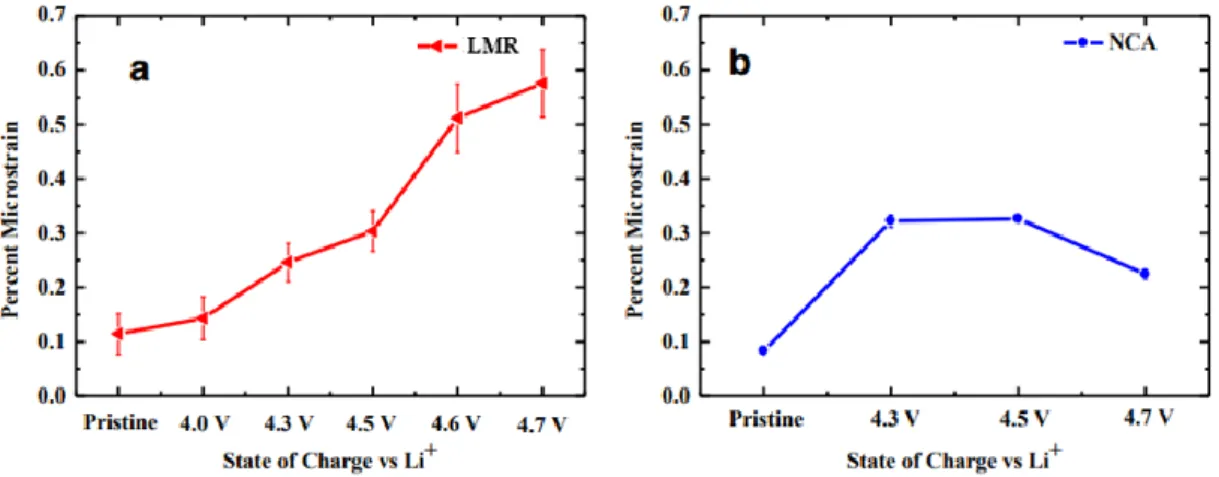
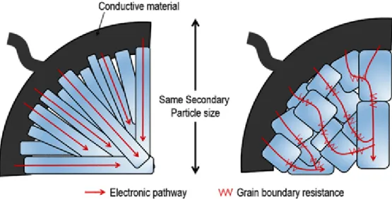
Comparison of microstrain changes for different loading states of (a) LMR and (b) NCA as determined from the Williamson–Hall analysis of the Bragg peak widths from conventional X-ray diffraction experiments on a large number of particles. These equations represent the reactions for the decomposition of LiPF6, which is the most commonly used salt in the liquid electrolyte. POxFyz compounds also form a non-uniform and thick SEI layer and destroy the interface.38 All cathode materials have common problems in the occurrence of side reactions with HF, and vigorous research has been carried out to prevent it.
The following equations show the reactions caused by the release of oxygen, which occur especially in LMR. In addition, CO2 reacts with oxygen radicals to generate C2O62-, which eventually becomes Li2CO3, a major component of the SEI layer.10 A schematic diagram of this mechanism is summarized in Figure 15. Schematic of the proposed sequential reaction mechanism within the closed system originates from the evolution of oxygen from the layered metal oxides Li−excess.10.
Previous researches to improve the performance of LMRs
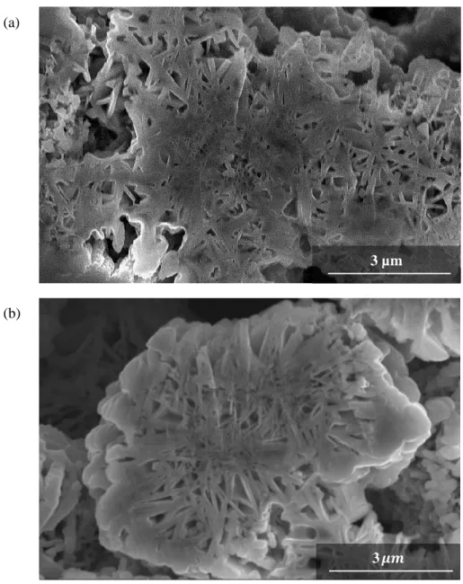
Oh et al.8 proposed a new design of LMRs, where the secondary particles are composed of large flake-type primary particles. Since the primary particles are well connected in one direction from the surface to the bulk, they can show high diffusion of lithium ions, as mentioned in the previous paragraph as the benefit of the rod-type morphology. There is some variation in specific enhancement depending on the coating materials, but the coating layer typically acts as a protective layer at the interface preventing excessive oxygen evolution and mitigating side reactions with the liquid electrolyte.
Zou et al.41 used EIS analysis to compare the resistance of the uncoated and 3 wt% Al2O3 coated sample. It implies that the coating layer can effectively mitigate the formation of unwanted SEI layers and improve the electrochemical kinetics at the interface. Sun et al.42 showed that the AlF3 coating layer not only alleviates the side reactions, but also stabilizes the particle structure by suppressing oxygen evolution at the surface.
Zheng et al.4 found out the detailed mechanism of the AlF3 coating layer with STEM and EELS analysis. This study showed that AlF3 coating made LMRs significantly activated in the first cycle, causing the surface reconstruction to the spinel-like phase. Even though the AlF3 coating could not completely prevent phase transition, there was a clear difference in the depth of the region where the structural transformation occurred.
Also, the AlF3 coating acts as a buffer layer, so it plays an important role in preventing the occurrence of corrosion caused by side reactions with the electrolyte. All these previous works have shown that surface coating enables LMRs to achieve better electrochemical properties. Schematic illustrations of the change in particle structure with and without AlF3 coating during cycling.4.
Objective in the works
Experimental section
The electrochemical performance was performed at the constant charge/discharge C rate of 0.2C in the voltage range of 2.5-4.7V for the first cycle, and 2.5-4.6V for the second cycle. After two forming cycles, the long-term cycle test was performed at 2.5-4.6V with charge/discharge C rate of 1C. The galvanostatic intermittent titration technique (GITT) was performed at constant C rate of 1C for 6 min with a rest time for 3 hours in the voltage range 2.0-4.8V.
The EIS test was performed with frequency range from 1MHz to 10MHz and a DC voltage amplitude of 10mV after fully charged to 4.6V. To observe the cross-sectional images of cathode materials, an ion milling system (model 1040 Nanomill, Fischione) was used. The ionic electrode and the morphology of the cathode powder were analyzed by scanning electron microscopy (SEM, Verios 460, FEI) attached with energy dispersive X-ray spectroscopy (EDX, XFlash® 6130, Bruker).
The crystallographic structure of the materials was investigated by X-ray diffraction (XRD) patterns using an X-ray diffractometer (Rigaku D/MAX 2500 V/PC) with Cu-Kα radiation. High-resolution transmission electron microscopy (HR-TEM, ARM300, JEOL) was used for structural and elemental analysis at the atomic scale. For TEM sampling, cross-sectional samples were prepared by two-beam focused ion beam (FIB, Helios 450HP, FEI).
Scanning transmission electron microscopy (STEM) images, energy dispersive X-ray spectroscopy (EDX) and electron energy loss (EELS) were obtained from it.
Result and discussion
Flake-type Co-free LMR cathode materials for high-energy density
According to the samples coated with 3 wt% AlF3-, the thickness of the coating layer is about 4-5 nm. Also, it appears that the overpotential in the sample coated with 5 wt% AlF3 is significantly higher. A schematic diagram of AlF3 coated particles after the first cycle is illustrated in Figure 35.
During the first cycle, chemical activation of the Li2MnO3 phase occurs from the surface of the AlF3 coated particles. The AlF3-coated sample can retain a higher discharge capacity than the uncoated sample of about 13.7 mAh/g. From the top graph in Figure 36, it appears that the capacity retention of the uncoated sample is slightly higher than that of the AlF3 coated sample.
However, considering the discharge capacity of the forming cycle, the AlF3-coated sample shows greater capacity retention. This new peak can also be observed in the uncoated sample, but its scale is much lower than the AlF3 coated sample. Considering the intensity of the peak in the second cycle, it is decreased even less dramatically in the AlF3 coated sample.
First, in the bulk region, the peak intensity of the uncoated sample decreased remarkably, while that of the AlF3 coated sample is maintained at almost the same level. The important point to note is the valence state of Mn in the AlF3 coated sample near the surface. This is closely associated with the aforementioned large reduction in the O-k edge peak of the AlF3-coated sample at the surface.
In the case of an uncoated sample, however, the peak intensity under all conditions is slightly lower than that of the AlF3-coated sample. The degree of change for the AlF3-coated sample is even greater than the uncoated sample.
Surface coating for high-performance LMR cathode materials
Conclusion
Zheng, J., et al., Functional Mechanism of AlF3 Coating on Li- and Mn-rich Cathode Materials. Zheng, J., et al., Structural and chemical evolution of Li- and Mn-rich layered cathode material. Thackeray, M.M., et al., Li2MnO3-stabilized LiMO2 (M = Mn, Ni, Co) electrodes for lithium-ion batteries.
Oh, P., et al., Superior Long-Term Energy Storage and Volumetric Energy Density for Li-Rich Cathode Materials. Han, J.-G., et al., Unsymmetrical fluorinated malonatoborate as an amphoteric additive for high energy density lithium-ion batteries. Singer, A., et al., Nucleation of dislocations and their dynamics in layered oxide cathode materials during battery charging.
Pan, H., et al., Li- and Mn-rich multilayer oxide cathode materials for lithium-ion batteries: a review from fundamentals to research and application progress. Li, X., et al., Direct visualization of the reversible O2−/O− redox process in Li-rich cathode materials. Carroll, K.J., et al., Probing the electrode/electrolyte interface in excess layered lithium oxide Li1.2Ni0.2Mn0.6O2.
Hwang, J., et al., Localization of excess Li triggers chemical irreversibility in layered Li- and Mn-rich oxides. Yan, P., et al., Intragranular cracking as a critical obstacle for high-voltage applications of layer-structured cathode for lithium-ion batteries. Fu, F., et al., Structure-dependent electrochemical performance of Li-rich multilayer oxides in lithium-ion batteries.