Introduction
General Introduction
To take more advantage of the cost-effectiveness of glass fiber reinforced plastics (GFRP), many researchers2-6 have tried to expand the application fields of these composites by engineering conductive GFRP with the help of conductive nanomaterials, such as carbon. nanotubes (CNTs), exfoliated graphite nanoplatelets (xGnP), graphene, etc., resulting in multiscale composites. In case (a), CNMs are first “pre-dispersed” in the resin and then incorporated within the micro-scale fiber reinforcements for composite fabrication.
Nanocomposite-Filled Microscale Fiber Reinforcements
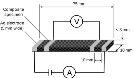
The result of the resistance measurement in the in-plane direction is shown in Fig.2.20 with spatial considerations. It indirectly provides information about the progressive state of the resin in the composite structure.
Carbon Nanomaterials-Coated Fiber Reinforcements
Problem Statement
- Filtration Monitoring
- Process Monitoring
At that time, the viscosity of the suspension should decrease due to the initiation of the cross-linking reaction. This is attributed to the increase in the volume conductivity of the yarn cross as the amount of CNT increases.
Objectives
Thesis Organization
The focus on the nanometer-scale additive (MWNT) that is part of the final composite excludes most. The research adopts a multi-phase approach combining both numerical and experimental methods to help lay the groundwork for a fundamental understanding of the fundamental physics governing the EMI shielding mechanisms of composite materials.
In Situ Flow And Filtration Monitoring of Multiwall Carbon Nanotube During The Manufacture of
Materials
The low frequency range is useful for distinguishing differences in the structure of the systems. The diagonal line of curve 1_2 then corresponds to the effective flow of the resin from point 1 to point 2. Fig.4.9 shows the conductivity of the composite samples as converted from the measured mass resistances.
In fig. 4.9 (a), it can be observed that when the thickness of the mid-plane MWCNT coating doubles from GF002 to GF003, the conductivity more than doubles. Evidence of the effect of yarn cross on experimental EMI SE of CM250 coated glass fiber composites. EMI shielding was found to improve significantly as a result of the absorption increase.
Composites Manufacturing and Filtration Assessment Technology
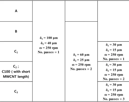
- MWCNTs Dispersion
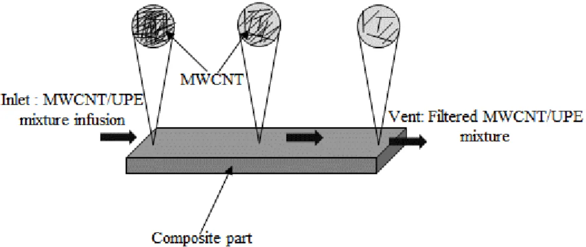
- Evaluation of CNT Filtration
- Multiscale Composite Manufacturing
- In Situ Data Acquisition
Characterization of Composites Before and After Infusion
- Differential Scanning Calorimetry (DSC)
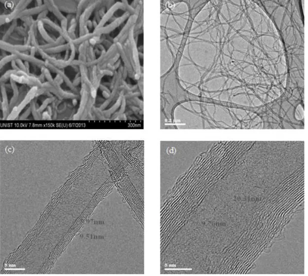
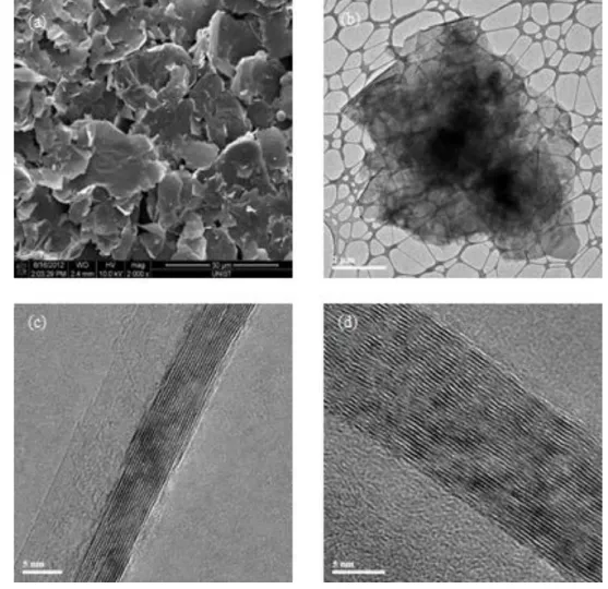
- Morphology Evaluation
- Rheological Measurements
- Bulk Electrical Resistivity Measurement
Due to the distinct nature of the material systems studied, they showed inconsistencies in EMI shielding performance over different frequency ranges. Samples GF002 and GF003 showed the same damping as the MWCNT coatings are located in the mid-plane of the composites.
Results and Discussion
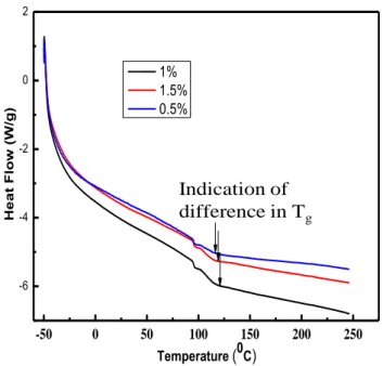
- DSC
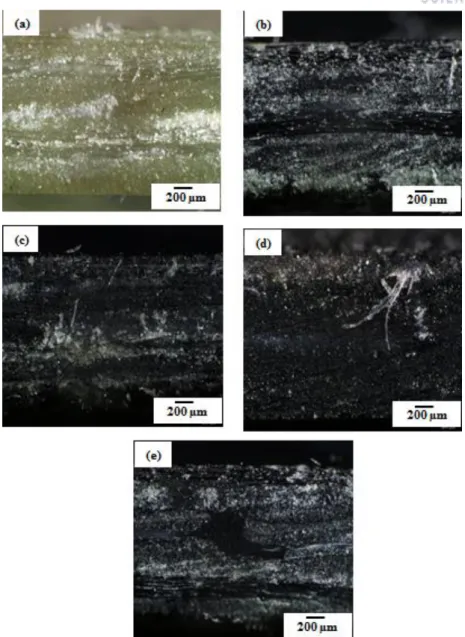
- Microstructural Characterization of MWCNT/UPE Mixtures and Composites
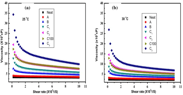
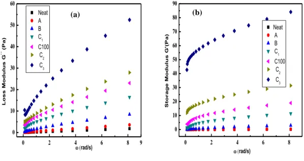
- Rheological Behavior
- Filtration Assessment
- Manufacturing with Case C 1
- Manufacturing with Case C 2
- Manufacturing with Case CM
- Manufacturing with Case C 3
- Tentative of Degree of Filtration Assessment of Porous Media by In Situ Resistance
- Electrical Properties of Composites
- Bulk Resistivity Measurements
- Current Voltage (I-V) Characteristic
- Interfacial Flow Monitoring
Summary
The filtration rate for each system was exhaustively analyzed based on the results provided by the measurement of the electrical system in situ. In the next chapter we will perform a whole process monitoring, but for fiber reinforcements coated with MWCNTs instead of premixed with resin. Second, and most importantly, manufacturing methods that allow for high-volume production by relying more on a fundamental understanding of the physics of the process than on the accepted practice of trial and error ingrained on the shop floor of manufacturing sites.
In this chapter we present an in situ process monitoring of hierarchical micro/nano composites using the carbon nanotube interwoven network that was used to coat glass fiber reinforcements, thus giving new functionality to the final composite during service.
Materials
In order for composites to be widely used, especially in consumer goods industries such as the aerospace, automotive and sports industries, two main goals must be achieved: - The cost of raw materials must continue to decrease. Process control is essential to the operation of any manufacturing process, and composite processes are no exception. Composites provide a wide variety of materials and processing methods, each of which may require different expectations and process control solutions.
Composites Manufacturing and Microstructure Analysis
As a result, path 1_2 alone can provide complete information of the resin flow within the composite material. On the contrary, composites consisting of two layers of carbon fiber and two layers of glass fiber textile, regardless of the stacking order, show three- to four-fold lower conductivity compared to the four-layer carbon fiber composites. Fig.4.10 shows the EMI SEs of the 12 composite panels, as predicted by the plane shielding theory (Sect.
The measured conductivity of the MWCNT coating was 33.98 S/cm, while the conductivity of carbon fiber supplied by the manufacturer was in the order of 1000 S/cm.

In situ Data Acquisition
Results and Discussions
- Quantifying Sensor Capability
- Tracking the Resin Flow Front
- Optimizing Sensor Capability: Effects of MWCNT Density and Length
- Effect of MWCNT Density
- Effects of MWCNT Length
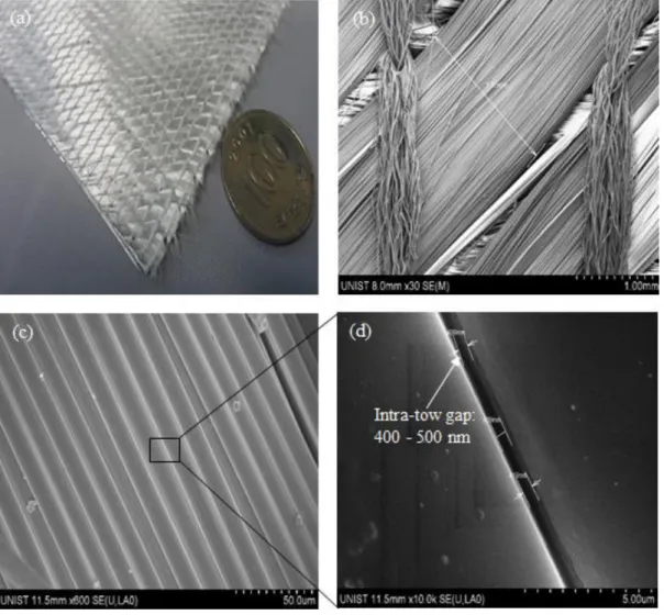
- Correlating S.E.M Images and Sensitivities
- A 3D Flow, Cure And Process Monitoring Using MWNT Percolated Network
- MWCNT Percolated Network-Induced Control of Large Scale Composite Parts
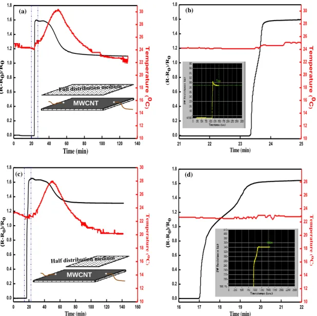
This suggests that the velocity in the top layer was higher than the bottom layer (the surface in contact with the mold), and thus the resin velocity in the middle layer of the interface was the lowest. This suggests that the front of the resin flow touched the bottom of the middle layer before the bottom layer. This observation forces the conclusion that cross-flow from the top to the middle layer dominated the in-plane flow after the resin had completed the wet half of all composites.
In both cases, the middle interface showed the lowest increase in resistance, suggesting that the resin distribution is not certainly the same throughout the composite.
Summary
In sequential injection, the injection length is reduced to the distance between the resin ports, thus dividing the parts into multiple injection regions. The problem here is that each of these regions must be completely filled to ensure wetting by the composite. 3.10 ((e), (f))) experienced an exponential increase in resistance only when they were fully wetted, thus proving the complete impregnation of the sub-section.
Additionally, they are placed perpendicular to the injection port as in sequential injection molding, so nanometer-scale additives, if well designed, can aid in control and automation for large-scale composite parts for intelligent manufacturing.
Electromagnetic Interference Shielding of Composites Consisting of a Polyester Matrix and Carbon
Theoretical
- Interaction Matter- Electromagnetic Wave: General Background
- Internal EMI Shielding Mechanisms
- Plane Shielding Theory
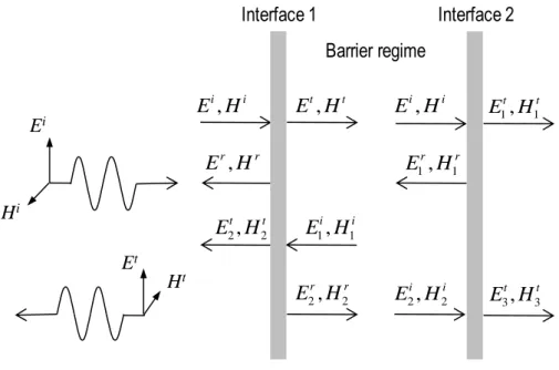
The ratio of the magnitudes of E and H for a uniform plane wave is the intrinsic impedance of the medium. The repeated reflections between the two interfaces are called "multiple reflections" and contribute to the overall reflection and absorption, giving the barrier's shielding effectiveness (SE). If there are no additional barrier materials, all the waves transmitted through interface 2 effectively reduce the SE of the barrier.
4.1 – Schematic representation of the shielding effectiveness of a conductive barrier to a uniform plane wave incident perpendicular to the surface.
Experimental
- Materials
- Composite Manufacturing
- Composites Characterization
- Microstructural Analysis
- Electrical Conductivity
- EMI Shielding Effectiveness
- Theoretical Predictions
- Measured EMI SE
- Design Optimization of Hybrid Carbon Nanotube/Graphene Nanoplatelet Based Multiscale
- EMI Shielding Effectiveness of Pure dielectrics
- Effect of Yarn cross on the EMI Shielding of MWCNT Coated Glass Fiber
- Effect of MWCNT Thickness
- Effect of Mismatched Conductive Layer
- EMI SE of CNM Coated Hybrid Fiber Composites
- Absorption-Wise Increase of EMI Shielding
The EMI SEs of the composite panels and the MWCNT-coated PET film were measured using the EMI SE test system manufactured by Rhode and Schwartz (Munich, Germany). On the other hand, increasing the thickness of the MWCNT coating, or separating the two coatings does not significantly affect the high conductivity of the four-layer carbon fiber composite (Fig.4.9 (b)). This can be attributed to the fact that when all the layers that make up the material are conductive, the reflection is governed by the conductivity of the outermost layer.
Regarding reflection, as discussed, the conductivity of the outer layer facing the incoming wave is critical, and the discrepancy is due to the difference in conductivity between the carbon fiber layer and the MWCNT coating. As the result suggests (Figure 4.14): Due to the dented structure of fabrics, EMI shielding is now determined more by the conductivity of the film than by the structure of the fillers. The surface topography of the fabric generates defects on xGnP and reduces the carrier mobility, as shown in Figure 4.15. It can be seen that (Fig. 4.16) as the resin is injected, due to the dented structure of fabrics, the EMI shielding is now determined more by the conductivity of the film than by the structure of the fillers, the topography of the fabric surface generates defects on xGnP by introducing wrinkles and thus reducing the wearer's mobility.
Summary
EMI SE of carbon fiber/glass hybrid composites and the effect of nanomaterial coatings. YC” and “GF” indicate a cross woven yarn with UPE, or cross woven yarn without UPE yarn, respectively, and “CNT” indicate a single MWCNT layer.
Conclusion and Future Work
Conclusions
In particular, we investigated the EMI shielding capability of MWCNTs and MWCNT/xGnP coated glass fiber hybrid reinforcements. The fundamental physics governing the EMI shielding mechanisms of materials, namely absorption, reflection, and multiple reflections, have been investigated and used in analytical models to predict EMI SE. Simulation and experimental results have shown that the contributions of reflection and absorption to electromagnetic interference protection increase with sufficient impedance mismatch, while multiple reflections have a negative effect.
However, they accurately predicted the relative shielding performance between composites, which makes the models a useful tool for optimal EMI shielding composite design.
Future Work
The outer surfaces refer here to the surfaces that are in contact with the mold and the skin layer respectively. In chapter 4 we demonstrated that the film as deposited in chapter 3 can not only serve for process monitoring, but can play a key role in the composite service life by influencing new functionalities to it. For a given amount of carbon nanomaterial in the glass fiber reinforced composite, it was found to maximize the conductivity and EMI shielding by coating the outer, instead of intermediate glass fiber layers with the MWCNT:xGnP weight ratio of 8:2. efficiency. The models showed a tendency to overestimate the SE, especially in the high-frequency regime.
In this section, the main MATLAB programs used for the numerical simulation are listed with a brief description of their functionalities.
Four Layers Glass Fibers Reinforced UPE
Four Layers Carbon Fibers Reinforced UPE
Four Layers: Alternated Carbon and Glass Fibers with Glass Fiber on Top
Four Carbon Fiber Layers with MWCNT Sprayed at the Outermost Layer, this is Top and
Four Glass Fiber Layers with MWCNT Sprayed at the Outermost Layer, this Is top and Bottom-99
Moldenaers, P.; Verpoest, I., Influence of carbon nanotube reinforcement on the processing and mechanical behavior of carbon fiber/epoxy composites. Sanchez, M.; Campo, M.; Jiménez-Suárez, A.; Ureña, A., Effect of carbon nanotube functionalization on the flexural properties of multigrade carbon fiber/epoxy composites produced by VARIM. K.; Han, K.; Park, J.-M., Electromagnetic interference shielding of composites composed of a polyester matrix and carbon nanotube-coated fiber reinforcement.
W.; Park, Y.-B., Piezoresistive behavior and multidirectional strain sensing capability of hybrid sheets of carbon nanotubes and graphene nanoplatelets.