Carbon nanotubes (CNTs) have been powerful candidates for decades across various applications such as electronics, energy storage, composites due to their excellent electrical, mechanical and structural properties. In this study, we tried heat treatment of single-walled carbon nanotubes (SWCNTs) and multi-walled carbon nanotubes (MWCNTs) as a post-treatment method from 1700℃ to 3000℃ for 10 minutes using a fast heating system based on joule heating which can be higher than 3000℃ heat up Both experimental results demonstrate the effect of heat treatment as post-treatment and may motivate mechanisms for structure-controllable CNTs.
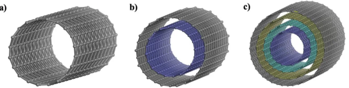
The connected two carbon nanotubes with "zipping" mechanism (c) The merged larger tube around 2.6 nm (From Ref. [52]).
Introduction
Carbon based materials
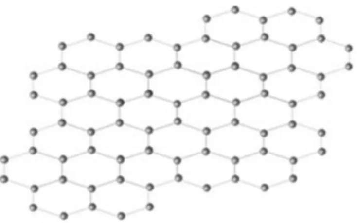
CNTs, simple-looking but excellent properties affected by the tube structure, have attracted the attention of many researchers as to how the CNTs with constant structure are synthesized. The reason for this is that to be applicable in different areas, controlling the structure-sensitive properties is essential. Two-dimensional carbon allotrope called "Graphene" is a hexagonal honeycomb structure. Sp2 hybridized material resembles one layer of graphite (Fig. 1.3).
Due to the thickness of the atomic scale, it has extraordinary properties that the new high modulus, strength, thermal conductivity, electricity and even transparency. Novoselov et al.6 presented about tearing of the single layer of graphite method using adhesive tape (Andre Geim and Konstantin Novoselov won the Novel Prize for physics in 2010). Diamond is well known as the hardest material on earth and low electrical conductivity because it has sp3 perfect crystal structure with strong covalent bonds which is the clear difference between sp2 hexagonal graphite structure; sp2 is related to electrical properties and sp3 is related to mechanical properties (Fig. 1.4)8,9.
Carbon nanotube (CNT)
- Structure and properties of carbon nanotube (CNT)
- Synthesis of carbon nanotubes
- Applications
Since the discovery of CNTs by arc-discharge method4, synthesis process for CNTs has been designed. The arc discharge method is known to produce highly crystalline CNTs, and a schematic of this method is shown in Fig. When the DC arc discharge current is applied, it raises the temperature and carbon vapor, which evaporates from the anode, is deposited on the opposite cathode.
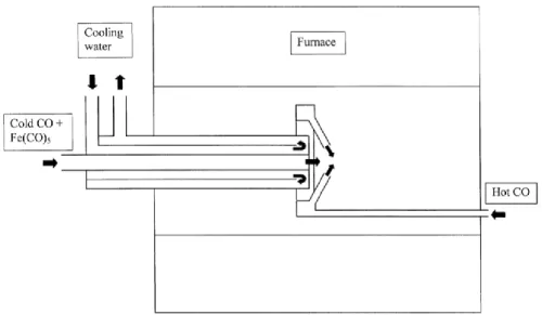
Zujin Shi et al.20 obtained the high yield SWCNTs by using Y-Ni alloy as anode catalyst. Chemical Vapor Deposition (CVD) method is the most widely used process to synthesize the CNTs so far due to low cost and high yield compared to arc discharge or laser ablation method. Nikolaev et al.29 designed the high-pressure carbon monoxide (HiPCO) method that can produce narrow diameter distribution nm) SWCNTs.
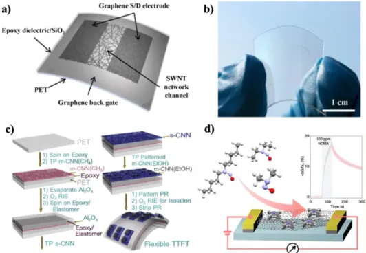
This process is suitable for mass production due to the continuous flow conditions of the catalyst and carbon feed gas. Carbon nanotubes have been candidates for various potential applications in the fields of electrical nanodevices, nanocomposites, energy storage and so on due to their advantages in excellent properties. Jang et al.33 reported carbon-based transistors with CNTs as semiconducting channel and graphene as electrodes (Fig. 1.12a-b).
Cao et al.34 introduced flexible and transparent thin-film transistors (TTFT) with SWCNT networks (CNN) as all part of semiconducting and conducting layers on plastic substrate (Fig. 1.12c. He35 report on CNTs sensor functionalized by cobalt ( III) tetraphenylporphyrin for the detection of N-nitrosamines (Fig. 1.12d) Mi et al.40 reported that the SWCNTs are much better than the MWCNTs for hydrogen storage, and therefore the hydrogen capacity increases with the size of the SWCNTs, but not in the case of the MWCNTs .
Besides these applications, there are inexhaustible ways to use the outstanding properties of CNTs, but these are strongly influenced by the structural and topological features that strongly influence the properties of CNTs.
Previous literature
- Heat treatment of CNTs
- Coalescence mechanisms of CNTs
López et al.53 proposed a fusion mechanism of SWCNTs bundle surrounding the center SWCNT. Inspired by this research, we attempted experimental study of heat treatment of HiPCO SWCNTs and MWCNTs from 1700 to 3000. Our results show that the diameter of SWCNTs increased with increasing the temperature and SWCNTs transformed to MWCNTs from 2500 ℃, especially, most MWCNTs have spurious number of walls such as 3- or 5-walled CNTs.
We demonstrated the odd-even effect through coalescence of SWCNTs, supporting previously proposed transformation mechanisms to MWCNTs. We also observed that various defects such as disconnected, bent and surface residues in the pristine MWCNTs disappeared and the quality was improved by heat treatment at high temperatures around 3000.
Experimental details
Materials
Experimental methods
- Rapid Heating System
- Raman Spectroscopy
- Transmission Electron Microscope (TEM)
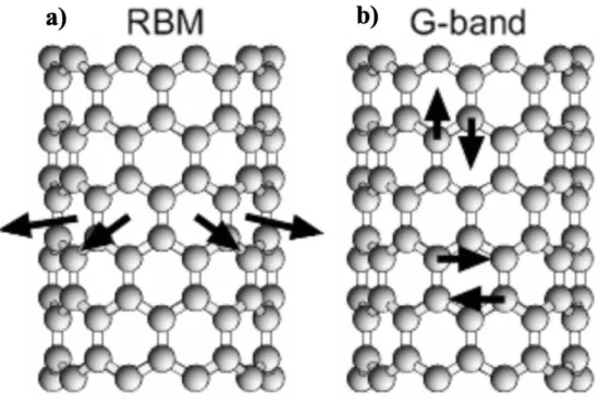
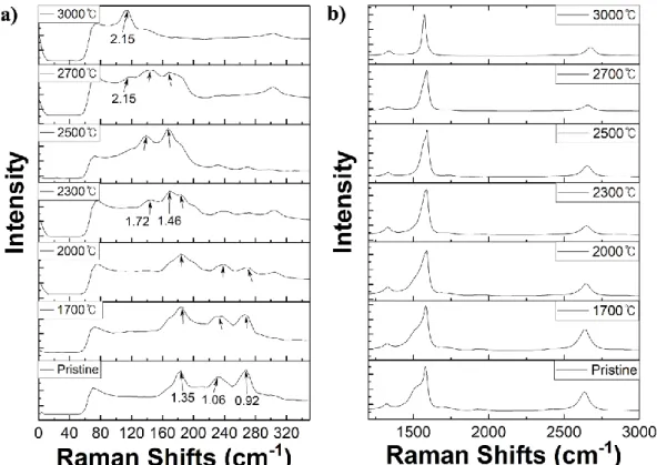
In this study, with these characteristics, the ramp speed was set to 10 seconds and the pressure was 770 Torr under Ar flow conditions. Raman spectroscopy has been used to characterize the structure of CNT, such as diameter, quality, and electrical properties; semiconducting or metallic. The radial breathing mode (RBM) peak arises from 80 cm-1 to 300 cm-1, caused by the vibrations of carbon atoms in the radial direction58 (Fig. 2.2a).
Because it is a peculiar condition that only appears in CNTs, the most useful way to define the diameter of SWCNTs is through the equation, d = 248/𝜔𝑅𝐵𝑀59.60. The G band, which is called the tangential mode, appears that C-C bond stretching can be observed around 1580 cm-1 (Fig. 2.2b). It can show the electrical properties of tubes which are semi-conducting or metallic with two separate peaks, G+ and G-peak.
Compare with semiconducting SWNT, the Lorentzian line shape, the metallic SWNT has a broader G peak, which is related to free electrons in CNTs58,61. In addition, the G-peak depends somewhat on the tube diameter, since MWNT, which has a large-diameter outer tube, appears as a single G-peak similar to graphite60. As the intensity of the D peak increases, there are more defects, so the G/D ratio has been mainly used to assess the quality of CNTs.
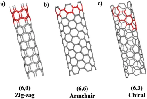
In this study, we used Raman spectroscopy with a 532 nm green laser to characterize the diameter and quality of CNTs. Transmission electron microscope (TEM) is the most powerful method to analyze the structure of CNTs, such as the diameter of the inner and outer walls, the number of walls, defects and chirality62. TEM images were used to determine the diameter, number of walls and figure out the quality of CNTs.
Results and discussions
HiPCO SWCNTs
- Pristine HiPCO SWCNTs
- Raman Spectroscopy
- Transmission Electron Microscope (TEM)
- Mechanisms about SWCNTs bundle transform to MWCNT
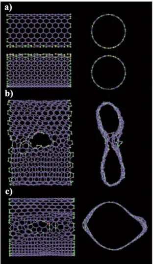
Although it is difficult to make out the diameter larger than 2.5 nm from the RBM tip, there may be larger tubes, and we believe that. To support the results from Raman spectra (Fig. 3.3), heat-treated HiPCO SWCNTs were characterized by transmission electron microscopy (TEM) (Fig. 3.4-9). Although diameters of SWCNTs cannot show obvious changes before 2000℃, iron clusters in tubes were eliminated compared to pristine SWCNT images (Fig. 3.2).
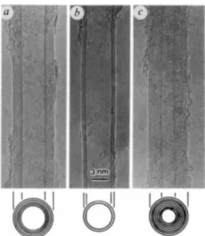
From 2500 ℃ (Fig. 3.7), SWCNTs start to transform to MWCNTs and these are much larger than enlarged SWCNTs. We can also see that the number of tubes in each bundle is much smaller than the pristine bundles. To study further, we characterized the number of walls in MWCNTs after heat treatment at 2700 ℃ (Fig. 3.10) and obtained the statistics based on these TEM images (Fig. 3.11).
We can see that the diameter distribution of CNTs is much wider than the pristine samples and all the CNTs smaller than 1 nm have disappeared, which implies that the CNTs with small diameter are attached to each other. the other and transform into bigger ones. Above all, the most unique feature is that the even number (double-walled, 4-walled tube) of CNTs is hard to find compared to the odd number (three-walled, 5-walled tube). This phenomenon makes it possible to predict the new mechanism that the transformation of the even number of CNTs is prohibited during the assembly of SWCNT bundles.
This process can also be continued to the formation of 5-walled CNTs by using much more SWCNTs around triple-walled CNTs (Fig. 3.12c). Further coalescence with (6,6) SWCNT again, the tube is still SWCNT of increased diameter, meaning that the sequential coalescence of SWCNTs leads to just greater single-wall-like SWCNT diameter doubling observed by P. The sequential coalescence of SWCNT' is small bundle induces a large SWCNT and the spontaneous fusion of surrounding SWCNTs always adds two layers to the center SWCNT.
Thus, due to coalescence of the SWCNT beam, MWCNTs have a (2n+1) wall that limits the even number of walls.
MWCNTs
- Raman Spectroscopy
- Transmission Electron Microscope (TEM)
The G/D ratio is the most effective way to evaluate defects in CNTs, with a higher value indicating better quality. After heat treatment at the temperature of 2500 and 2800℃, the intensity of G peaks is higher than that of D peaks, in which the G/D ratio is ≈ 1, which still seems similar to the pristine sample. When heat treated at 3000℃ for 30 minutes, the G/D ratio increases by nearly 1.2, indicating an increase in crystalline area and improved purity.
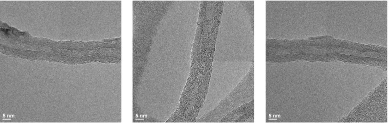
Huang et al.67 on heat treatment of MWCNTs as the effective purification method, but they described that defect healing of MWCNTs takes a long time. To further study about the quality changes by heat treatment, we compared pristine sample and heat treated at 3000℃ for 10 minutes by TEM and high resolution TEM (HR-TEM). Besides rough and residual surface in pristine, heat-treated samples are smoother and very straight, although residues were not completely removed (Fig. 3.18).
Similar to this mechanism, disconnected amorphous graphitic region can grow new tubes by interconnecting due to a limited high concentration of carbon atom confined in the outer tube.
Conclusions
CVD growth of single-walled carbon nanotubes with narrow diameter distribution on Fe/MgO catalyst and their fluorescence spectroscopy. Gas-phase production of single-walled carbon nanotubes from carbon monoxide by the HiPco process: A parametric study. Highly flexible, transparent thin-film transistors using carbon nanotube-based conductors and semiconductors with elastomeric dielectrics.
Fusion of single-walled carbon nanotubes and formation of multiwalled carbon nanotubes under high-temperature treatments. Effect of heat treatment on the structure and stability of multiwalled carbon nanotubes produced by catalytic chemical vapor deposition technique. Multiple inner tube junctions in the inner tube of peapod-derived double-walled carbon nanotubes: theoretical study and experimental evidence.
Acknowledgements
![Figure 1.4 Crystal structure of (a) graphite (b) diamond (from Ref. [8])](https://thumb-ap.123doks.com/thumbv2/123dokinfo/10497998.0/16.892.194.683.676.960/figure-1-4-crystal-structure-graphite-diamond-ref.webp)
![Table 1.1 Comparison between SWNT and MWNT (from Ref. [11])](https://thumb-ap.123doks.com/thumbv2/123dokinfo/10497998.0/17.892.136.811.877.1060/table-1-1-comparison-swnt-mwnt-ref-11.webp)
![Figure 1.8 Schematic of arc-discharge method process (From Ref. [18])](https://thumb-ap.123doks.com/thumbv2/123dokinfo/10497998.0/20.892.200.686.437.724/figure-schematic-arc-discharge-method-process-ref-18.webp)