Submitted a project report in partial fulfillment of the requirements for the award of Master of Engineering (Electrical). One of the most important solutions for this is the development of the Energy Storage System (ESS).
Problem Statements
This is the main factor for the ease and continuous growth of the mode of transportation, ie. air, road, water. The effect of DC traction system variables affecting the amount of regenerative braking energy.
Aim and Objective
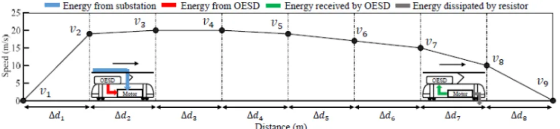
For the purpose of multi-train simulation, the dynamic train motion is derived for the evaluation of energy recovery to the system. Modeling of simulation traction between the station should evaluate the system developed (Saleh et al., 2017).
Scope of Study
This chapter outlines the context of the research that is relevant to the nature of the discipline. The details of the significance of the study and the design of the study design will be further explained.
Implementation Energy Storage System
The research history provides general knowledge on the impact of energy storage system adoption in Malaysia's urban transit system, with a cross-reference to other advanced rail systems, and on the widespread implementation of energy storage systems of capable of potential benefits. and challenges eg, reducing the burning of fossil fuels, as well as the greenhouse effect. According to the International Energy Agency (IEA), rail is one of the most efficient modes of transport, accounting for 9% of global passenger traffic and 7% of freight traffic.
Research Background
The optimization of the energy storage system is shown in figure 2.3 Proposed action to save energy. The illustration of the hybrid energy storage system in figure 2.5 The hybrid energy storage system (Qu and Yuan, 2021).
Energy Storage System Awareness and Improvement
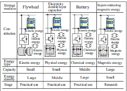
The factor of selection Energy Storage System
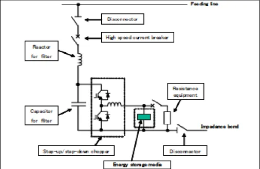
The author (Sirmelis, Zakis and Grigans, 2015) stated that it is necessary to mention that this last point has a significant impact on the architecture of the storage system. Regarding information in Figure 2.6 Japan railway Energy Storage System (Okui et al., 2010) showed that the voltage drop between DC substations has been remarkable as the electrical load has increased. In many cases, an energy storage system requires a power converter, i.e. an inverter, a converter or chopper equipment.
The standard design of an energy storage system for electrification purposes includes a step-up/step-down chopper ie. DC chopper. Figure 2.7 A Japanese railway DC chopper shows the primary circuit for an energy storage system (Okui et al., 2010).
Adoption Energy Storage System
Energy Storage System toward Renewable Energy Policy
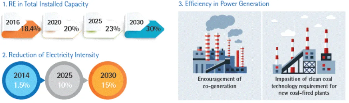
In 2000, the 4 Fuel Policy was transformed into the 5 Fuel Policy, which declares it as the 5th fuel in the renewable energy supply mix (The Eighth Malaysia Plan 2001-2005). It was emphasized by the new policy that 20 percent renewable energy is available in its 2025 generation mix, while the national COP21 contribution was supported. In Peninsular Malaysia, energy storage systems do not include generation of renewable energy, solid waste, hydro-small waste, biomass, biogas, solar energy and.
Similarly, 2 percent said they will investigate the action before investing in renewable energy resources (Alam et al., 2016). For this reason, strategic planning is needed to influence the implementation of renewable energy in larger companies, micro-enterprises and households, especially in the construction project of the railways.
Railways System
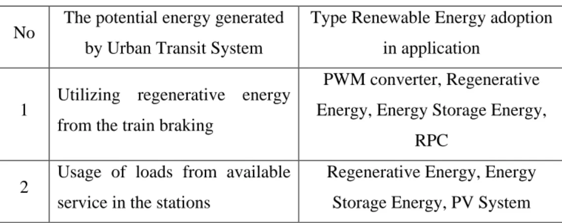
In Japan, in addition to silicon rectifiers for the DC traction power supply system, the regenerative inverter was introduced more than 20 years ago (Hayashiya et al., 2012a). The traction power generation system will convert excess electricity in the AC and DC systems of the train into 3 modes, one of which is to: .. convert the power to the stations/inject loads or inject the electricity into the traction system spray; A prototype experiment was carried out with the possibilities of recharging the traction power supply in the light tram (Kameya et al., 2014), a battery bank with two storage batteries of 17.5VC, primary and 15 VDC as secondary.
There are 2 viable sources in the journal approach viz. wind and solar, but solar energy is used as a renewable energy source in this prototype. According to a case study and data collection in the Istanbul metro network (Demirci and Celikoglu, 2018) Infra and the system contribute the same energy consumption, studies for the optimization of regenerative braking and side use.
Energy Storage System in Railways System
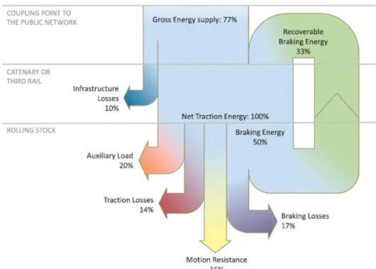
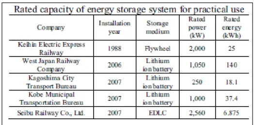
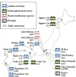
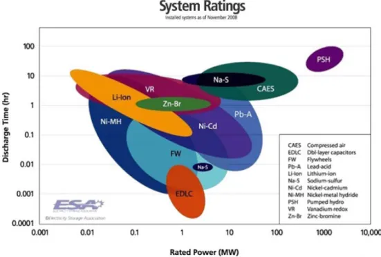
The train consumes 50 percent of the total energy consumed by the railway system and the author believes that the increase in energy consumption requires more research into energy efficiency. From the above Figure 2.10 Profile of the battery bank for the energy storage system, the different installed energy storage systems, which included different battery products and the final energy record of 80 MW. According to the author's table (Leadbetter and Swan, 2012), the supercapacitor (ELDC) system is easily chosen due to the current technology limitations and the implementation cost is significantly higher when compared to the battery system.
A critical analysis by the author (Leadbetter and Swan, 2012) indicated that the energy storage system contributed between 2.5 and 15 percent to the grid system. A summary of the energy storage system is shown in the table in Figure 2.11. Battery characteristic (based on author's source) shows the battery characteristic of another type of supplier (Leadbetter and Swan, 2012).
Introduction
Research Methodology
Research Workflow
Research Sequence
Data and Information
Raw Data and literature review
The literature review of the previous research and study will explain and elaborate the detailed requirement of the energy storage system. The system characteristic simulated by the ETAP will help to replicate the fundamental of the characteristic and help the studies on the energy storage system.
Simulation Study
Analysis information
Modelling of railway power supply and distribution system
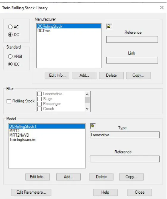
The operating scenario is the same, but it is different when the application of regenerative braking is carried out in traction with dynamic train movement. In simulation, the train motion allocation is allocated to simulate the final run. It is important and necessary to consider the worst possible scenario of the largest rolling stock that will operate in the railway network.
The simulation run is fixed in schedules and progress and a summary of the result will be discussed in the next chapter. From the simulation study, the energy characteristic during operation was simulated based on schedule and progress.
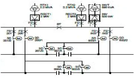
Alternative Current (AC) and Direct Current (DC) Network The main power supply distribution is illustrated in Figure 3.5
The collected data from the simulation must be explained and assigned to an appropriate energy storage system.
Introduction
Information and simulation data
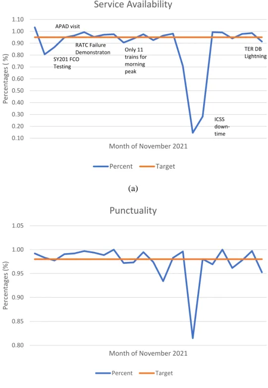
We can conclude that the average accuracy is 98%, which is sufficient for the minimum requirements of the traffic operator. The average service availability is 95%, which meets the minimum service availability requirement. The energy generated by the dynamic motion of the train is highly dependent on the overall performance of the system and is not covered by this research.
The actual energy produced is measured and recorded to tabulate the actual energy received and stored in the energy storage system. This is also in line with the requirements of the authorities in accordance with energy efficiency in the large scale of energy consumption by the end user, i.e. railway operator, shopping complex, etc.
Results
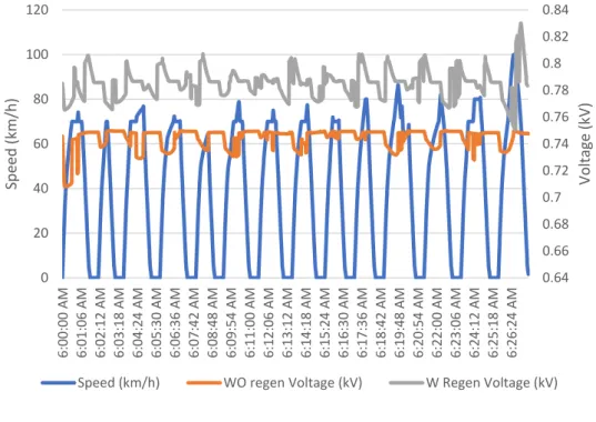
Operation without regenerative braking shows that the voltage fluctuates between 750 VDC and 900 VDC. However, the voltage swing for the case with regenerative braking is between 750 VDC and 830 VDC. This is due to the injection of regenerative braking energy into the DC network, which causes the voltage to rise.
The characteristic of these scenarios illustrated in Figure 4.3 shows the current fluctuation during regenerative braking and the contribution of the energy to the system. It is very different from the result of applying regenerative braking to the traction power supply.
Case study: Energy profiles for the trains
Single train with and without regenerative braking
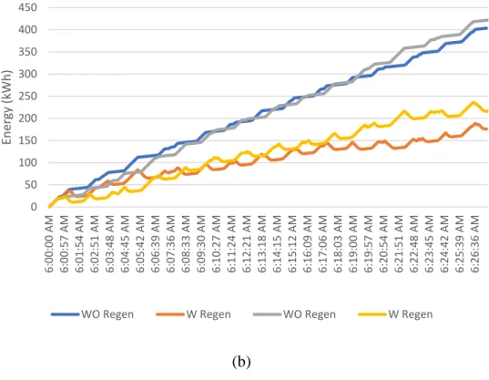
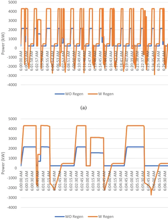
From Figure 4.5, it can be seen that the energy that can be obtained is illustrated in (a) and (b). From Figure 4.6, it can be seen that the energy that can be obtained is illustrated in (a) and (b). The observation in the simulation study showed that the power from the train produced a large amount of energy.
The amount of energy from the dynamic motion of the train is an important component that must be used to design the optimal solution for the energy storage system. The amount of energy used is more and could be used in an energy storage system.
Finding of the results
Design of Energy storage system
From the modeling of the railway line and graphics in figure 3.5, the maximum duration for the regenerative braking is up to 30 seconds. Based on the literature review, current implementation of the Energy Storage System (ESS) and the outcome of the result, the supercar technology is chosen to store the regen. Considering the capacity, it is noted that the capacity of the Energy Storage System is estimated at 6,315 kW.
The power conditioning for the system must be designed to accommodate the size of the Energy Storage System. The amount of energy was explained based on the author's finding for reference and future studies.
Recommendations
It is also noted that the grid power supply is important to initialize the power for railway operation, but the implementation of renewable energy, i.e., energy storage system is one of the options to reduce the current focus from all countries to reduce global warming and towards a green environment. As mentioned in the previous chapters, it is complementary to use the type of battery for two (2) main purposes either the compensation voltage drop or the fixed energy storage system. Justification of the selection criteria of project solutions for climate control systems based on renewable energy sources.
Methodology for sizing energy storage for mass transit DC roadside: application to the case study of the French railway company. Adaptive Eco-Driving strategy and feasibility analysis for electric trains with built-in energy storage devices.