Identification Of Potential Energy Harvesting Technique From KTM Railway Track
By:
Mohamad Hakim Bin Abdul Rahman 19370
Dissertation submitted in partial fulfilment the requirements for the Bachelor Of Engineering (Hons)
(Civil)
SEPTEMBER 2017
Universiti Teknologi PETRONAS, Bandar Seri Iskandar,
32610, Teronoh Perak Darul Ridzuan.
i
CERTIFICATION OF APPROVAL
Identification Of Potential Energy Harvesting Technique From KTM Railway Track
By
Mohamad Hakim Bin Abdul Rahman 19370
A project dissertation submitted to the Civil Engineering programme Universiti Teknologi PETRONAS In partial fulfilment of the requirement for BACHELOR OF ENGINEERING (HONS.)
(CIVIL)
Approved by,
___________________________________
(DR MUSLICH HARTADI SUTANTO)
Universiti Teknologi PETRONAS Bandar Seri Iskandar
32610, Teronoh Perak Darul Ridzuan
September 2017
ii
CERTIFICATION OF ORIGINALITY
This is to certify that I am responsible for the work submitted in this project, that the original work is my own except as specified in the references and acknowledgements, and that the original work contained herein have not been undertaken or done by unspecified sources or persons.
______________________________
(MOHAMAD HAKIM BIN ABDUL RAHMAN)
iii ABSTRACT
Rail transport in Malaysia comprises of heavy rail including commuter, light rapid transit (LRT), monorail, airport rail link and a funicular railway train. The railway network covers 12 states excluding Sarawak. The increasing of citizens in the country has made the traffic become crowded and people have chosen public transport as the main transport to every destination. Considering that railway track and it surrounding has higher chances to produce the sources of renewable energy, a research has been made in order to find out the energy that can be produce from various sources and the suitable device that can be used to harvest the energy. This study is crucial as harvesting electricity from the renewable energy will give a lot of contribution to the country. Besides, it also enhances the uses of green technology which purposely to reduce the pollution around the globe. This research is focusing on identification of energy harvesting on KTM railway track in Malaysia. At the end of this research, the best method of harvesting and the suitable devices to harvest potential energy from railway track will be proposed. The study will involve by doing a lot of research, the study of the costing of the device and the output produce by each devices.
iv
ACKNOWLEDGEMENT
First of all, I would like to express my gratitude to my supervisor, Dr Muslich Hartadi Sutanto for his encouragement and guidance throughout the process of finishing my FYP. He had shared valuable insights in the relevance knowledge which is truly helped the progression and smoothness of this research. All of his effort will not be forgotten.
Next, I would like to thank AP Indra sati Hamonangan Harahap and AP Ir Dr Hisham Mohamad for their kind advice and comment during my project presentation which help me a lot in putting a relevant and more details in my FYP.
Last but not least, I am indebted with my family members and friends for their support which give the strength and endless motivation for me to finish my studies.
v
TABLE OF CONTENTS
CERTIFICATION OF APPROVAL ... i
CERTIFICATION OF ORIGINALITY ... ii
ABSTRACT ... iii
ACKNOWLEDGEMENT ... iv
CHAPTER 1: INTRODUCTION ... .1-2 1.1 Background 1
1.2 Problem Statement 2
1.3 Objective 2
1.4 Scope of Study 2
CHAPTER 2: LITERATURE REVIEW ... 3-8 2.1 Mechanical Energy Harvesting Device 4
2.1.1 Mechanical Energy Source 5
2..2 Thermal Energy Harvesting Device 5
2.2.1 Thermal Energy Source 6
2.3 Solar Energy Harvesting Device 6
2.3.1 Solar Energy Source 7
2.4 Electromagnetic Harvesting Device 7
2.4.1 Electromagnetic Source 7-8 2.5 Sustainability of Harvesting Device 8
CHAPTER 3: METHODOLOGY ... 9-17 3.1 Introduction 9
3.2 Project Work 10
3.2.1 Initial Phase 11
3.2.2 Second Phase 12-13 3.2.3 Last Phase 13
3.3 Project Key Milestone 14
3.4 Gantt Chat FYP 1 15
vi
3.4.1 Gantt Chart FYP 2 16
3.5 Tools Required 17
CHAPTER 4: RESULTS AND DISCUSSION………18-31 4.1 Cost Analysis 30-31 CHAPTER 5: CONCLUSION AND RECOMMENDATION……….32
5.1 Chapter Overview 32
5.2 Conclusion 32
5.3 Recommendation 32
REFERENCES……….33-35 APPENDICES.……….36-37 APPENDIX-1: Solar Train In India 36
APPENDIX-2: Piezoelectric harvesting device by Innowattech 37
vii LIST OF FIGURES
Figure 1- Sequences of project work 10
Figure 2- Annual Solar Radiation in Malaysia 13
Figure 3- Train Speed (km/h) vs Frequency (Hz) 22
Figure 4- Train Speed (km/h) x Power (10*-8 kWh 23
Figure 5- Total Potential Energy for the whole track in a day kWh/m2/day 25
Figure 6- Potential Energy Output Per Train (kWh/m2/day) 27
Figure7-Potential Energy Output For Photovoltaic Nose Barrier (PVNB) (kWh/m2/day) 28
Figure 8- Annual Temperature at Perak in 2016 29
LIST OF TABLES Table 1- Challenge and Output Of Harvesting Energy 3
Table 2-Ambient Energy System 4
Table 3-Classification of mechanical Sources 5
Table 4-The comparison between the harvesting devices 8
Table 5-The Track Vibration Analysis 18-19 Table 6-Factors Related to Vibration Source 19-20 Table 7-Vibration Produce for four types of rail system 21
Table 8-Value of frequency (Hz), Energy and Power (kWh) based on Train Speed (km/h) 22
Table 9-Value of frequency (Hz), Energy and Power (kWh) based on Train Speed (km/h) 24
Table 10-Energy Produce by Solar Train Photovoltaic Noise Barrier (PVNB) 27
Table 11-The LCOE for solar train and photovoltaic noise barrier 31
1
CHAPTER 1
INTRODUCTION
1.1 BACKGROUND
Energy produce in some activities are usually wasted. Some of the process comes from the motors, engines, bulbs and others which comes from the surrounding activities. However, researchers nowadays have find out that this energy can be converted into electricity which then can be generated on small device rather than be wasted. Energy harvesting device capture some of this wasted energy, convert it into electricity and use it in various applications. These energies come from a lot of sources, such as wind, light, thermal and mechanical vibrations. The well-known energy harvester are photovoltaic for solar energy, thermoelectric generator for heat, energy piezoelectric for mechanical energy and electromagnetic energy from electromagnetic source. The energies produced can be stored into diode and capacitance for further usage. Each device harvester can give different output and harnessing the energy will help in reducing the using of electricity from power supply. For smaller scale, the energy captured can supply small device such as mobile phone, small device and so on. Computing cost will be cut significantly if the energy lost were harvested and used into other applications. For future prediction, this harvesting energy may be crucial in reducing the dependence to the electric supply such as from fossil fuels. In this research paper, the author will explain the energy that can be harvested for a railway track and discussed the device that available for that processes.
2 1.2 PROBLEM STATEMENT
Harnessing energy from railway track are not a new idea to the West Country. The researchers have found the way to harness the energy and make used to it. However, the ideas are still not commercialized and the energy are not fully optimized in order to produce electricity. In Malaysia, this idea are still on preliminary studies, which still need a lot of research to be implemented in the country. Implementation of this idea are really challenging as a lot of aspect need to be consider and the output of this application must be high in order for this idea to be commercialized. The mechanism that will be used must be affordable compare with the energy that will be harvested.
For train, harvesting the vibration energy is the most obvious source of energy in the railway track (Wei & Jing, 2017) as most research paper only discuss the energy come from vibrations that are harvested from the railway track.
So this paper will be proposing some of the devices and mechanism that can be apply to the KTM railway track in order to harvest potential energy for further usage.
1.3 OBJECTIVE
The objective of this research is:
• To review the available device to harvest energy from KTM railway track.
• To analyse the most potential device that can be used to harvest energy at KTM railway track
1.4 SCOPE OF STUDY
This project focus mainly on how to harvest energy from KTM railway track.
There will be research on the device that are suitable to be implemented and the data that will be used to give some results.
3
CHAPTER 2
LITERATURE REVIEW
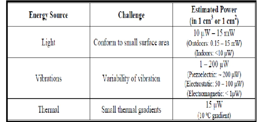
Every harvesting device will give different challenge and output. As describe by Torres and Rincon-Mora, energy harvesting device must be described by their power density which is power produced, rather than energy density for example the abundant source of energy from surrounding. He also described that every harvesting device has different challenge that can affect the production of the power output such as describe in the table 1 below:
Table 1: Challenge and Output of Harvesting Energy (Torres & Rincon-Mora)
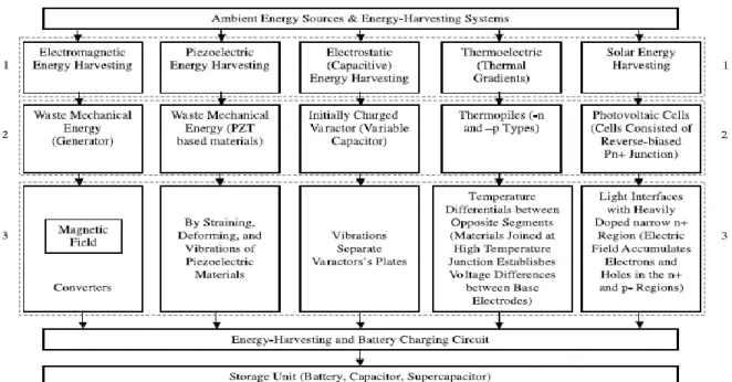
Besides, considering that the source are varies and each source need a proper method of harvesting technique will also influence the maximum power density produce by each harvesting device. Yildiz in Potential Ambient Energy Harvesting Sources and Technique, has made research on five harvesting device. Each device harvested ambient energy from different type of sources and the reaction of each device are manifested in table 2:
4
Table 2: Ambient energy system (Yildiz)
2.1 MECHANICAL ENERGY HARVESTING DEVICE
Piezoelectric is one of the most famous harvesting device that are applicable in converting mechanical energy into electricity. Well known from its function that convert mechanical source which are stress, strain and vibration that come from body motion, vibration, noise, air flow and many other sources. Piezoelectric generate electricity after mechanical stress and vibration are applied on the device and the electricity comes from the properties of the crystal that have electric charge on it which has create the piezoelectric device. The materials that have made the piezoelectric are Ceramic, Composite, Polymers and Mono Crystals. This device are also been adjusted so that it can suit how it will be used. For example after a rapid development, there have been invention of piezoelectric nanogerator which have given more research to fabricate other type of piezoelectric device. This invention are focusing in harvesting energy from various sources such as vibrations, sound, rain drops, bending, stretching, muscle movements, inhalations and wind to generate energy. Instead of converting into electricity, the piezoelectric can also act as vice versa such as to convert back the electricity into mechanical energy.
5 2.1.1 MECHANICAL ENERGY SOURCES
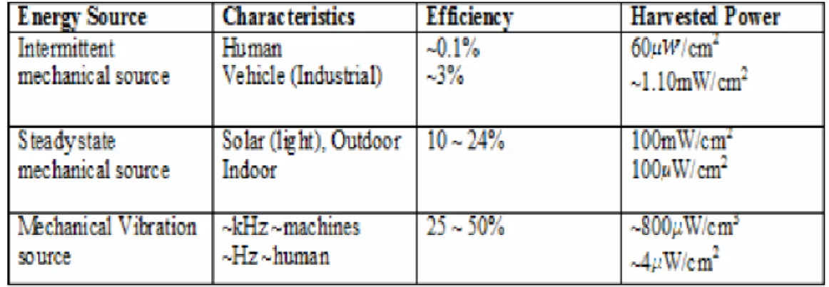
There are few classification of mechanical sources which are intermittent mechanical source, Steadystate mechanical source, and Mechanical Vibration source.
For intermittent mechanical source, the sources come from human activities and vehicles which can generate thermal energy from motions and so on. Next, Steady state mechanical sources come environment which are wind, water flow, ocean waves, and solar energy. While for mechanical vibration sources comes from machinery, stress and strain from motor and waste energy from machine which are captured into ambient energy. (Yusof, Yatim, Samosir, & Abdulkadir, July 2013)
Table 3: Classification of mechanical sources (Yusof, Yatim, Samosir, &
Abdulkadir, July 2013)
2.2 THERMAL ENERGY HARVESTING DEVICE
Thermal energy harvesting device can be used for heating, cooling and conversion of heat into electricity. It is widely used in industries such as for automotives can span into different area and industries such as waste-heat for automotive and power generation in remote space mission. However, this written are only focusing on the function of device to convert energy into electricity. For thermal energy harvester, thermoelectric generator (TEG) is one of the device that contribute into this function. This is based on the Seeback effect that was discovered by Thomas Johan Seebeck. He found that a circuit made from two different metals, with junctions at different temperatures would deflect a compass magnet. He quickly realized that
“Thermoelectric Force” develop an electrical current, which by Ampree’s law deflects the magnet. More specifically, the temperature gradient produces and electric potential
6
(voltage) which will trigger electric current in a closed circuit. Based on the seebeck effect, the efficiency of the thermoelectric devices is determined by the thermoelectric materials figure of merit, ZT, which is the result of several mixing coefficient. High efficiencies of the TEG comes from high figure of merit. TEGs are attractive for a large variety of applications, in particular in the fields of green and renewable energy harvesting. (Daniel, 2017)
2.2.1 THERMAL ENERGY SOURCES
Thermal energy can be obtain from various sources such as waste heat energy from heater, furnace and friction sources. Besides, this energy can also be gathered from human and animals activities which come from body motion such as running and walking. Thermal energy are abundant because it can be caused by a lot of factor including from the solar harvesting.
2.3 SOLAR ENERGY HARVESTING DEVICE
Photovoltaic (PV) effect are not new in the harvesting world. Used in a lot of application to harvest solar energy into electrical energy. This system will convert solar energy to electricity in the form of voltage or electric current. This system are widely used in industries to generate electricity around the world. Photovoltaic have been installed in various application such as in building, on the roof, in agriculture, street light and so on. Photovoltaic consist of solar cell which come from semiconducting materials that manifest photovoltaic effect convert light into electricity. A PV are equip with solar panels that comprises with solar cells. It is consider as the cleanest device harvesting because it generate no pollution and greenhouse emission. PV act as a medium when the light hit the solar cells on it, they produce electricity by the movement of photons and electron in the circuit. (Tiwari, Mishra, & Solanci, 2011). The PV efficiency will decrease under room light in indoor situations compare to where sunlight is available.
7 2.3.1 SOLAR ENERGY SOURCES
Solar energy are consider the most important renewable energy as the sources are infinite, universal, and environmental friendly. Even though there are no electric supply in a certain location, solar energy can be the sole source of electricity that will be charge in a battery for daily usage. Hence, solar energy can be the major contribution of electricity. Solar energy is gathered from sunlight and is consider as the main resources of renewable energy.
2.4 ELECTROMECHANIC HARVESTING DEVICE
Electromechanic harvesting device has gain attention by the researcher as it can convert vibration or motion into electricity. This device use the principle of converting vibration that can be the most source in supplying potential energy from railway track. Based on Prof Kumar, Prof Balpande, & Prof Anjankar (2016), electromagnetic energy harvester with Mechanical Motion Rectifier (MMR) can make a full use of vibrations-like railroad track deflection produce by train. This device is suitable for this project as vibration can be the most source in supplying potential energy from railway track. Vibration from railway track is trigger from the deflection of moving train on the railway track thus will be converted into electricity.
Recent studies show that a devices was invented by Wang, Penamalli & Zuo (2012) which convert linear motion to rotary motion based from the displacement of railway track. Then the rotational motion are used to rotate a permanent magnet direct current which then will produce electricity.
2.4.1 ELECTROMECHANIC SOURCES
Electromechanic harvester mix the concept of mechanical system and electromagnetic which use the principle of Faradays Law of electromagnetic induction whereby an induced current are form when a coil moving into the magnetic field. (Prof Kumar, Prof Balpande, & Prof Anjankar, 2016) The fundamental of electromagnetic involve the using of conductor and magnet to produce current. The mechanical system are convert into electricity by the
8
magnetic generator. Majority of the electrical motors, transformers, inductors and generators are based on this fundamental. A simple example for the device which use this concept is generators. When the generator vibrates, the oscillating mass has a relative displacement with respect to the housing. The magnetic induction generator converts this relative displacement into electrical energy.
2.5 SUSTAINABILITY OF HARVESTING DEVICE
The meaning of sustainability of harvesting device here is the ability of the device to replace the electrical supply in producing the electricity of adequate energy to the consumer. The energy is consider sustainable if the energy consume is lower than the energy harvest. In order to know that the energy are consider sustainable, the device or the energy gathered must be able to supply energy to consumer without any external assistance. In other meaning, self-sustainability of the harvesting device is actually depending on the energy obtain and how much it will be converted into electricity. For energy to be considered self –sustainable, the energy harvested can be used by consumer for infinite amount of time until the power outage or power failure.
(Gurucharya & Hossain, 2 MAY 2017)
Table 4: The comparison between the harvesting devices.
9
CHAPTER 3
METHODOLOGY
3.1 INTRODUCTION
A research methodology define the sequence of theoretical analysis and method apply to a field of study. Different field of study will produce different type of flow. However, they still follow the consequences of how to do the research and how to display the result. Methodology will link the theoretical analysis and the body of method with the knowledge that are applied. Typically it comprises concepts such as paradigm, theoretical model, phases, quantitative or qualitative techniques.
Methodology will not provide solution but it is consider as a method. However, this method will reach the reader to a more deep understanding. Overall, of research system characterizes as the procedure used to gather the data and information with the end goal of settling on business choices. The philosophy may incorporate distribute research, interviews, overviews, surveys and other research strategies which could incorporate both present and authentic data.
10 3.2 PROJECT WORK
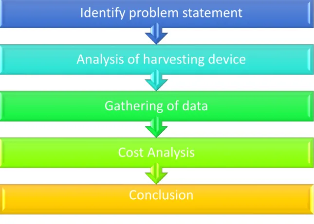
Figure 1: Sequences of project work
A few sequences have been followed in order to produce a good writing. The sequences involve are compressed into five processes:
Process 1: Identify Problem Statement Process 2: Analysis of harvesting device Process 3: Gathering of data
Process 4: Cost Analysis Process 5: Conclusion
From all of the process and phases, this proposal research has been divided into several phase. Process 1 and 2 are considered as the initial phase, process 3 and process 4 where all the body and framework of the research to gain information, while process 5 is the conclusion of the best device or model that should be implemented.
Conclusion Cost Analysis Gathering of data
Analysis of harvesting device
Identify problem statement
11 3.2.1 INITIAL PHASE
The first phase is consider as the crucial phase because a problem must be issued and gather in order to be solve and to propose a good project. For this project, ambient energy, or energy that are produce by surrounding are usually wasted. In Malaysia, harvesting the ambient energy is still in preliminary step as only small scale on industry are focusing to use this wasted energy as the source of electricity which is focusing more on solar energy as to produce energy. Besides, bases on the analysis, there are result that shows that Malaysia use fossil fuels, including oil, gas and coal as the main source of energy. Even though, Malaysia has abundant of natural gas and crude oil, these sources may be depleted someday and they also produce harmful substances to the environment. As a consequences, renewable energy, potential energy and green energy will be the other sources in supplying the electricity and power supply to the industry. Compare to the West Country, there are a lot of research and implementation of other source of energy to produce electricity. As for this project, small scale of research is made up to implement the harvesting of ambient energy into electricity. Based on the title, identification of potential energy on KTM Railway track, this project will involve the study of suitable device to be implemented in railway track focusing the railway track in Malaysia. Even though in West Country, there are research based on this basis, but the different factor and situation must be considered which mean that the condition for the railway track in Malaysia will be different compare to the West Country. Beside, study on harvesting energy on the railway track is still not fully discuss. The research are focusing more to harvest energy from mechanical sources such as vibrations.(Wei & Jing, 2017)
For these project, a few devices are selected according to their harvesting ability. Deep understanding and studied of the devices mechanism have to be made in order to find the best comparison for these project. The devices are piezoelectric, photovoltaic cell, and thermoelectric generator. Each device can harvest different type of ambient energy and each suitability uses on railway track are further discuss in the results.
12 3.2.2 SECOND PHASE
Second phase involve the process of gathering as much information to produce a good result and a good analysis. For this phase, the result are studied based on their effectiveness and the correct equation that can be applied.
Besides, the costing of the device and the suitability to implement the device on the railway track also will be discussed. For railway track, a lot of details must be obtain on site and a calculation or modelling need to be done to produce the essential result. The details, may be consist of the train speed, the temperature, the weather and the condition of the surrounding of the railway track. For general, Electric Train Services (ETS) under KTM has provide 18 services daily between Monday to Thursday while 22 services from Friday to Sunday (M.Lowtan, 14 January 2014). Based on these information, it can trigger on how much the energy produce based on the railway traffic. Besides, there are already research using piezoelectric and photovoltaic cell, so the information from the research can be link to the details gather from the railway track to produce sufficient information. From evaluation of potential solar energy in Malaysia by Aziz, Wahid & Arief (2016) show the solar radiation in Malaysia. Based on the research, the average annual average solar radiation in Malaysia is 1643kWh m-2 and the energies are sources for water pumping, domestic water heating and so on. These data show the solar intensity in Malaysia is abundant and correlate to this research in producing electricity by photovoltaic cell.
13
Figure 2: Annual Solar Radiation in Malaysia (Aziz, Wahid, Arief, & Aziz, 2016)
3.2.3 LAST PHASE
Last phase is consider the choosing of the best device to be implemented. Based on the result obtain, comparison will be made and the result will be discussed. At last, the output for the research will show the information that are linked to problem statement and the purpose of the research. The formula of Levelized Cost Of Electricity (LCOE) is used to measure of a power source which attempts to compare different methods of electricity generation.
14 3.3 PROJECT KEY MILESTONE
Details/Week
1 2 3 4 5 6 7 8 9 10 11 12 13 14 15
FYP I FYP title selected
FYP title approved
Submitted Extended Proposal Proposal Defence
Submitted Interim Report Draft Submitted Interim Report
FYP II Submission Of Progress Report
Draft
Submission Progress Report Pre-SEDEX
Submission of Final Report Draft Submission Of Final Report Submission Of Technical Paper Viva
Submission Of Hardbound
15 3.4 GANTT CHART- FYP 1
Details/Week 1 2 3 4 5 6 7 8 9 10 11 12 13 14
Preliminary research on possible FYP title
Selection of title
Approval title by Supervisor and Coordinator
Collect Resources For Research Research For Proposal Draft Input Discussion with Supervisor Submitted Extended Proposal Conduct Research
Prepare Slide For Proposal Defence presentation
Proposal Defence Presentation
Research for Interim Report Draft Input Submission Of Interim Report Draft Submission Of Interim Report
16 3.4. 1 GANTT CHART- FYP 2
Details/Week 1 2 3 4 5 6 7 8 9 10 11 12 13 14 15
Recap from FYP 1 Gathering data Analysis Data
Discussion with Supervisor
Submission Of Progress Report Draft
Submission of Progress Report Prepare poster for Pre-SEDEX Pre-SEDEX and submission of Final Report Draft
Submission Of Dissertation &
Technical Paper Prepare slide for viva Viva
Submission Of Project Dissertation (hardbound)
17 3.5 Tools Required
AutoCAD
This tool is used to create modelling.
Abode Acrobat 6.0
This software is used to review digital documents and references such as manual, report and standards.
18
CHAPTER 4
RESULT AND DISCUSSION
Based on the study made by Nordin et al (2016), the range of electricity produce by PZT can range between 382 microwatt at 40km/h to 397 microwatt at 160km/h and this range can be used to estimate the electricity that can be produce by PZT for KTM railway track. However, the vibration produce at KTM will not be exactly the same as the research need to consider a lot of aspect such as the load of carriage, the length of the train carriage, the environment and the speed of the train.
Besides, railway generate more noise and vibration if the speed of the train is higher.
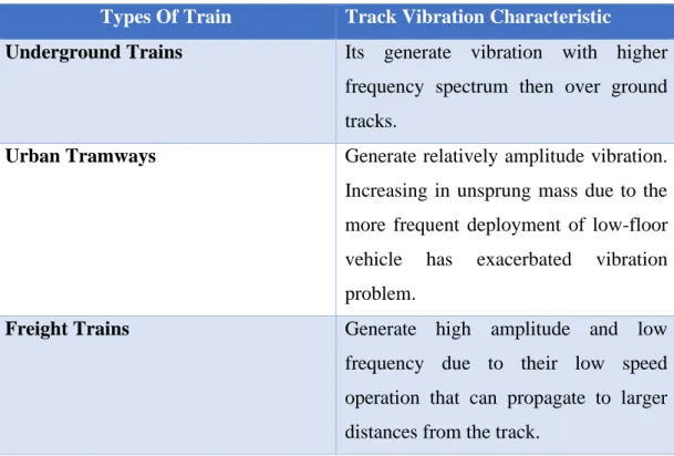
There are also differences on the train and train vibration characteristic based on the type of the train which is shown in the Table 5.
Table 5: The Track Vibration Analysis (Nordin, Mohd Nasirin, Ghazali, & Azis, 2016) Types Of Train Track Vibration Characteristic
Underground Trains Its generate vibration with higher frequency spectrum then over ground tracks.
Urban Tramways Generate relatively amplitude vibration.
Increasing in unsprung mass due to the more frequent deployment of low-floor vehicle has exacerbated vibration problem.
Freight Trains Generate high amplitude and low frequency due to their low speed operation that can propagate to larger distances from the track.
19
High Speed Trains Generate elevated amplitude vibration due to their increased speeds. Vibration levels may become magnified if their speed become comparable to the wave speed in the supporting soil.
Besides, the vibration produced of the train can be based on several factors which is shown in the Table 6.
Table 6: Factors Related to Vibration Source Factors Related to Vibration Source
Factors Influence
Vehicle Suspension If the suspension is stiff in the vertical direction, the effectiveness forces will be higher on transit cars, only the primary suspension affects the vibration levels, the secondary suspension that supports the car body has no apparent effects.
Wheel Type and Condition Normal resilient wheels on rail transit system are usually too stiff to provide significant vibration reduction. Wheel flat and general wheel roughness are the major cause of vibration from steel wheel/steel rail system.
Track/Roadway Surface Rough track are always the cause of vibration problem. Maintaining a smooth vibration will reduce vibration levels.
Speed Higher speed will result higher vibration levels
Depth of Vibration Source There are significant differences in the vibration characteristic when the source
20
in underground compared to the ground surface.
Transit Structure The vibration from a lightweight bored tunnel will usually be higher than a pured concrete box subway.
Track Support System On rail system, the track support system is one of the major component in determining the levels of ground borne vibration. The highest vibration levels are created by track that is rigidly attaches to a concrete tracked. The vibration levels are much lower when special vibration control track system such as resilient fastener, ballast mats and floating slabs are used.
So based on the Table 6 the level of the vibration produce is depending on the several factors and the higher the vibration produce the higher electricity can be produced. However, all of the factors has it limits to be considered as exceeding the limit will cause something terrible to the railway track and the environment. Based on that, there are already research collaboration between Prasarana Negara Berhad and Keretapi Tanah Melayu Berhad which has study the vibration and the noise produce on four type of selected rail transport system. The study is shown in the Table 7. This table can be the basis in calculating the output for the electricity produce from the railway station. LRA and LRB is the light rail system, LRT, while MRL means monorail and CTR is KTM commuter.
21
Table 7: Vibration Produce for four types of rail system (Nordin, Mohd Nasirin, Ghazali, & Azis, 2016) No Types of rail
system
Displacement (µm)
Vibration Velocity (mm/s)
Ranking
1 LRA 0.33553 0.03234 1
2 LRB 0.14408 0.03400 2
3 MRL 1.67692 0.42292 3
4 CTR 0.85608 0.08517 4
*Ranking is based on displacement and vibration velocity
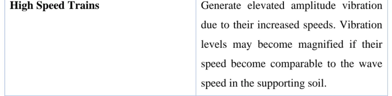
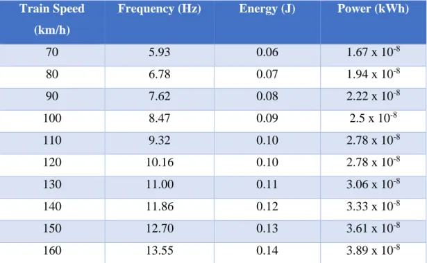
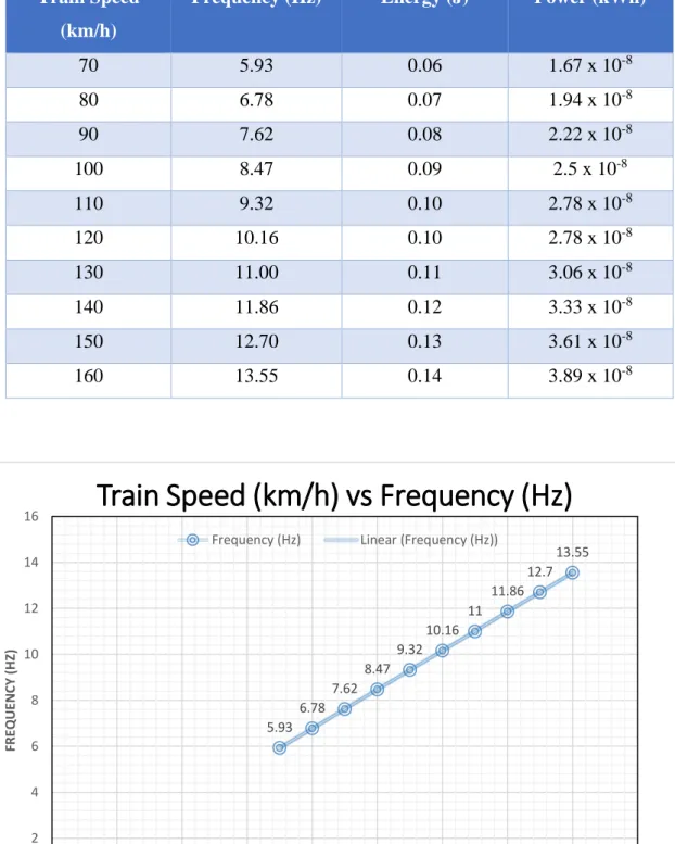
Theoretically, the piezoelectric can be calculated based on the frequency of the trains. In the article by energy harvesting from the vibration of passing train by Cleante et al (2016), the energy produce by train is increasing when frequency of the train increase. The research start by harvesting energy from the train with a speed of 162 km/h and frequency of 13.72 Hz which produce the energy of 0.14 J. Then experiment was continued to the train with the speed of 180 km/h (15.14Hz), 195 km/h (16.57 Hz) and 200 km/h (16.86) which produce 0.18 J, 0.26 J and 0.27 J. By referring to the maximum speed of the train in Malaysia which is 160km/h, it can be assume that the frequency produce will be less than 13.72 Hz which is 13.55 Hz. While the speed may be varies because of the track condition and the route, interpolation can be made based on different speed which will be from 70 km/h until 160km/h. The frequency based on the speed will be 5.97Hz, 6.78Hz, 7.62Hz, 8.47Hz, 9.32 Hz, 10.16 Hz, 11 Hz, 11.86 Hz, and 12.7 Hz. The highest and the lowest energy output will be 0.06J and 0.14 J which produce power of 1.67 x 10⁻⁸kWh and 3.89 x 10⁻⁸kWh in a one passing train.
Frequency of the train = 𝑋
𝑇𝑟𝑎𝑖𝑛 𝑠𝑝𝑒𝑒𝑑 (𝑘𝑚
ℎ )
x
13.72162 𝑘𝑚/ℎ
Energy = 𝑥
𝐹𝑟𝑒𝑞𝑢𝑒𝑛𝑐𝑦 (𝐻𝑧)
x
0.14𝐽13.72 𝐻𝑧
Power = 𝐸𝑛𝑒𝑟𝑔𝑦 (𝐽)
𝑇𝑖𝑚𝑒𝑠 (𝑠)
22
5.93 6.78
7.62 8.47
9.32 10.16
11 11.86
12.7 13.55
0 2 4 6 8 10 12 14 16
0 20 40 60 80 100 120 140 160 180
FREQUENCY (HZ)
TRAIN SPEED (KM/H)
Train Speed (km/h) vs Frequency (Hz)
Frequency (Hz) Linear (Frequency (Hz))
Table 8: Value of frequency (Hz), Energy (J) and Power (kWh) based on Train Speed (km/h)
Train Speed (km/h)
Frequency (Hz) Energy (J) Power (kWh)
70 5.93 0.06 1.67 x 10⁻⁸
80 6.78 0.07 1.94 x 10⁻⁸
90 7.62 0.08 2.22 x 10⁻⁸
100 8.47 0.09 2.5 x 10⁻⁸
110 9.32 0.10 2.78 x 10⁻⁸
120 10.16 0.10 2.78 x 10⁻⁸
130 11.00 0.11 3.06 x 10⁻⁸
140 11.86 0.12 3.33 x 10⁻⁸
150 12.70 0.13 3.61 x 10⁻⁸
160 13.55 0.14 3.89 x 10⁻⁸
Figure 3: Train Speed (km/h) vs Frequency (Hz)
23
1.67 1.94
2.22 2.5
2.78 2.78 3.06
3.33 3.61
3.89
0 0.5 1 1.5 2 2.5 3 3.5 4 4.5
70 80 90 100 110 120 130 140 150 160
Power (10*-8kWh)
Train Speed (km/h)
Power (10*-8kWh)
Figure 4: Train Speed (km/h) x Power (10*-8 kWh)
Based on the information given by Palikhel (2015) in his research, he manage to create a model of stainless steel cantilever beam which attach with a couple of piezoelectric to copy the real world energy harvesting in intermodal transport system which change the vibration energy into electricity. The beam will have six piezoelectric attach on it and the size will be 200 mm x 85 mm x 0.54 mm. The main focus of the research is to create the maximum power output when a multiple piezoelectric on the stainless steel cantilever beam are having the frequency ranging from 20 Hz to 1000 Hz. For the maximum output of 20 Hz, the value will be 4.516 µW. For commercial purpose, the consideration design may be taken from the commercialized piezoelectric pad from Innowattech in Israel railway track as they put two generator at each of the railway sleepers to replace the patch between the sleepers and the rail. As in Malaysia, the total length of railway track own by KTMB is 1677 km which is using a metre gauge track (1000mm width) and average of 1660 sleepers for 1 km of the railway track. Considering for 1000m2, there will be 3320 of piezoelectric can be installed and for 1m2 will be around 4 units. The power output from the piezoelectric for one passing train and variable of speed can be calculated as:
24 Energy = 𝑋
𝐹𝑟𝑒𝑞𝑢𝑒𝑛𝑐𝑦 (𝐻𝑧) x 4.516 𝑥 10
−3𝑊
𝐹𝑟𝑒𝑞𝑢𝑒𝑛𝑐𝑦 (𝐻𝑧) x 1 hour Total Generators/m2 = 4𝑋 𝐸𝑛𝑒𝑟𝑔𝑦 𝑓𝑜𝑟 𝑜𝑛𝑒 𝑔𝑒𝑛𝑒𝑟𝑎𝑡𝑜𝑟 = 2.29𝑥4 = 9.16 µWh/m2/day
Total Generators = 2 𝑋 𝑡𝑜𝑡𝑎𝑙 𝑠𝑙𝑒𝑒𝑝𝑒𝑟𝑠 𝑋 𝑔𝑒𝑛𝑒𝑟𝑎𝑡𝑜𝑟𝑠 = 2 x 1660 x 1677 = 5567640
Total Energy Output =
𝑃𝑜𝑤𝑒𝑟 𝑥 𝑇𝑜𝑡𝑎𝑙 𝐺𝑒𝑛𝑒𝑟𝑎𝑡𝑜𝑟𝑠 𝑥 𝑜𝑛𝑒 𝑝𝑎𝑠𝑠𝑖𝑛𝑔 𝑡𝑟𝑎𝑖𝑛 𝑖𝑛 𝑎 𝑑𝑎𝑦
Table 9: Value of frequency (Hz), Potential Energy and Total Energy Based (kWh/m2/day) on Train Speed (km/h)
Train Speed (km/h)
Frequency (Hz)
Potential Energy for
One Generators
(µW)
Total Potential Energy for
1m2 (kWh/m2/day)
Total Potential Energy for
the whole track in a day
(kWh/day)
70 5.93 1.34 5.36 x 10⁶ 7.46
80 6.78 1.53 6.12 x 10⁶ 8.52
90 7.62 1.72 6.88 x 10⁶ 9.58
100 8.47 1.91 7.64 x 10⁶ 10.63
110 9.32 2.10 8.40 x 10⁶ 11.69
120 10.16 2.29 9.16 x 10⁶ 12.75
130 11.00 2.48 9.92 x 10⁶ 13.81
140 11.86 2.68 10.72 x 10⁶ 14.92
150 12.70 2.87 11.48 x 10⁶ 15.98
160 13.55 3.07 12.28 x 10⁶ 17.09
25
Figure 5: Total Potential Energy (kWh/day) for the whole track in a day Sung in Extraordinary Minds Discuss Idea (2012) wrote that Malaysia receive 4000 to 5000 Wh/m2/day energy from the sun which can best used to produce electricity for 11 years. Under the 10th Malaysian plan, the Malaysia government want the 5.5% of total electricity in 2015 to come from renewable energy. However, currently only small percentage of electricity are produce by solar energy. Besides, the cost to utilise the solar system is high. Based on the cost of PV installation on 2012, the average cost of PV system per kW peak was RM15000 even though the cost is falling from RM31410 at year 2005. The price is still unaffordable for the Malaysian.
Based on the research, there are four types of PV solar panels available in Malaysia which are mono-crystalline silicone (Mc-Si), poly-crystalline silicone (Pc-Si), copper- indium-diselenide (CIS), and thin film amorphous silicon (A-Si). Each of the PV solar panel has efficiency less than 10%. For example, the efficiency of Mc-Si, Pc-Si, CIS and A-Si are 6.9%, 5.1%, 4.0% and 2.2%. Thus, for a small scale, the annual solar radiation measured in Ipoh in 2012 is 4.54 kWh/m2. So based on the highest efficiency which is 7% (Mc-Si), the solar energy that can be used will only be:
4.54kwh/m2/an x 0.07= 0.3178 kwh/m2/an
Besides, for solar powered train, there are already countries that implements solar harvesting which can powered the system for the train such as light, information
7.46 8.52
9.58 10.63 11.69
12.75 13.81
14.92 15.98
17.09
0 2 4 6 8 10 12 14 16 18
70 80 90 100 110 120 130 140 150 160
Total Potential Energy for the whole track in a day (kWh/day
Train Speed (km/h)
Total Potential Energy for the whole track in a
day (kWh/day)
26
display and fans. India expected that by installing the solar panels on the top of train will reduce the usage of diesel for 21,000 litres per year (krishna, 2017). However, the usage of solar panel on moving train will reduce the efficiency of the solar panels. The usage of the solar panels on the rooftop of the train in India reduce the efficiency from 20% to 16% even though they have been using high efficiency solar panel. (Kavya Darshana, Kaustubh, Ganesh, & Sheela, 2015). Still in a large scale, the harvesting device can contribute to a green environment. The solar energy can be calculated by using the formula:
E= A * r * H * PR E= Energy (kWh)
A= Total solar panel Area (m2) r= solar panel yield (%)
H=Annual average irradiation on tilted panels (shadings not included)*
PR= Performance ratio, coefficient for losses (range between 0.9 and 0.5, default value =0.75)
In India, the solar train was installed with 16 solar panel for each carriage and the installation have given output of 7200 kW annually. In Malaysia, Ktm Class 91 and Ktm Class 93 is consider as the fastest train use in the country with the maximum speed of 160km/h. The train has a length of 138 m with 6 cars and each car has a length of 22.95 m. Referring the installation of solar panel on train in India, both train can be installed with the same method of installation to calculate the solar output that can be extracted from the train. Each carriage of the train are designed to fit with 16 solar panel each has an area of 2 m2. The total area expose to the sunlight on the solar train will be 192 m2.The efficiency of the will be 16 %. Based on the formula for one train and different annual solar irradiance in different places, the power produce are stated on the figure 6:
For second approach, the solar panel can also be installed along the railway track which can also act as a noise barrier. The average losses in a year for the PVNB will be 3% and the current uses of the solar panel will have efficiency of 14%-16%.
The formula will be the same but the solar panel will be installed on both side of the railway track. Taking solar panel efficiency as 13%, using the same formula of E = A
* R * H *PR, and by calculating for 1m2 of solar panel that can are exposed for different region the value are stated in the table 10:
27
Table 10: Energy Produce by Solar Train and Photovoltaic Noise Barrier (PVNB)
Bil Region
Average Annual Solar
Radiation (kWh/m2)
Daily Solar Radiatio
n (kWh/m
2)
Solar Train
Photovoltaic Noise Barrier (PVNB)
Solar Conversion
Efficiency
Potential Energy Output per train(kWh/d
ay)
Potential Energy Output per m2(kWh/m2/
day)
Solar Conversio
n Efficiency
Potentia l Energy
Output (kWh/m
2/day)
1 Kuching 1470 4.027
0.16
92.78 0.483
0.13
0.393
2 Bangi 1487 4.074 93.86 0.489 0.397
3 Kuala Lumpur 1571 4.304 99.16 0.516 0.420
4 Petaling Jaya 1571 4.304 99.16 0.516 0.420
5 Seremban 1572 4.307 99.23 0.517 0.420
6 Kuantan 1601 4.386 101.05 0.526 0.428
7 Johor Bahru 1625 4.452 102.57 0.534 0.43
8 Senai 1629 4.463 102.83 0.536 0.435
9 Kota Bharu 1705 4.671 107.62 0.561 0.455
10 Ipoh 1739 4.764 109.76 0.572 0.464
11 Taiping 1768 4.844 111.61 0.581 0.472
12 Georgetown 1785 4.890 112.67 0.587 0.477
13 Bayan Lepas 1809 4.956 114.19 0.595 0.483
14 Kota Kinabalu 1900 5.205 119.92 0.625 0.507
Figure 6: Potential Energy Output Per Train (kWh/day)
92.78 93.86 99.16 99.16 99.23 101.05102.57102.83107.62109.76111.61112.67114.19119.92
0 20 40 60 80 100 120 140
Potential Energy Output Per Train (kWh/m2/day)
Region
Potential Energy Output Per Train (kWh/day)
28
0.393 0.397 0.42 0.42 0.42 0.428
0.434 0.435
0.455 0.464
0.472 0.477
0.483 0.507
0.483 0.489
0.516 0.516 0.517 0.526
0.534 0.536
0.561 0.572
0.581 0.587
0.595 0.625
0 0.1 0.2 0.3 0.4 0.5 0.6 0.7
Kuching Bangi Kuala Lumpur Petaling Jaya Seremban Kuantan Johor Bahru Senai Kota Bharu Ipoh Taiping Georgetown Bayab Lepas Kota Kinabalu
Energy Output (kWh/m2/day)
Region
Potential Energy Output For Solar Energy
Potential Energy Output of Solar Train Per m2 (kWh/m2/day)
Potential Energy Output For Photovoltaic Nose Barrier (PVNB) (kWh/m2/day)
Figure 7: Potential Energy Output For Photovoltaic Nose Barrier (PVNB) (kWh/m2/day)
Ktm railway track consist of 1677 km length of track. Assuming that each side of the track installed the PVNB along the length of KTM railway track and taking the lowest potential energy output which is 0.393 kWh/m2/day. The total energy that can be harvested daily will be 1318122 kWh/m2/day.
Since TEG use Seeback effect in changing heat into electricity, the figure of the annual temperature at Ipoh might be useful to retrieve some information to use TEG in converting surrounding temperature into electricity. As we know, there are already research on the usage of TEG to convert body heat from human into electricity.
The electric produce even though in a small range which is around 5 ma to 20 ma is already a good success. Human body have a temperature around 37 degree and based on that, the heat produce can be used to change into electricity. Based on the figure 7, the highest temperature recorded is 38 degree which is at March 2016. This information is important to show that harvesting energy from temperature mostly in this research such as at railway track can give high chances to produce a good feedback. However, to use TEG and to produce high electricity, the device need to
29
capture a lot of potential difference whereby the device need to have higher temperature at the hot side and lower temperature at the cold side of the device.
Figure 8: Annual Temperature at Perak in 2016
As the research has already an end, a conclusion has been made that thermoelectric generator cannot be implemented as a device harvester on a railway track. These device is usually attach to an engine to create a higher temperature gradient which can produce higher power output. Considering the surrounding temperature is too low and there is no studies implemented for thermoelectric generator at railway track, the device need to be fabricated in order for it to harvest energy at railway track.
Piezoelectric and solar photovoltaic produce different energy output. However, based on the research, the implementation of solar photovoltaic can give a higher energy outcome which can be commercialized for further usage. Piezoelectric need to be fabricated in order to be implemented at railway track besides the device produce small amount of energy compare to solar photovoltaic.
30 4.1 COST ANALYSIS
The calculation of LCOE can be expressed by:
𝐿𝐶𝑂𝐸 = 𝐶1 + 𝐶2 𝑤 + 365 + 𝑦
Where:
C1= Cost each solar panel C2= Cost of installation W= Energy output Y= Service life
To find the LCOE, the total cost of the photovoltaic system will be divided with the total energy generated over lifetime. For Photovoltaic Noise Barrier (PVNB), the noise prevention by photovoltaic module was presented at Switzerland in 1989.
During that time, TNC installed the world’s first PVNB at Swizerland with one kilometre length and area of 928 m2. There are 2208 module were installed which have given an annual yield of 100 MWh, the total cost of 1699500 euro (83 mil) and have operated more than 28 years. The cost are high enough considering that the solar photovoltaic price in the past are high enough while the efficiency is less. For 1m2 of PVNB module, the cost will be RM89450. Hence, taking the average energy output in Malaysia 0.44kWh/m2/day, the LCOE will be:
𝐿𝐶𝑂𝐸 (𝑝𝑣) 89450 0.44𝑥365𝑥𝑌
In the article from The Indian Press, the Indian Railways has launched a solar diesel train which has six trailer coach and two motor coaches. The trailer coach which is also called a passenger coach was equipped with a 16 solar panels that each cost Rs 9 lakh (RM57528) and can produce 300 watts power each. The train and the solar panel has a lifespan for 25 years. The cost for passenger cost is Rs 1 Crore (RM 639182) and the motor Coaches cost Rs 2.5 Crore (RM1587955). It is estimated that the annual power yield by a solar train are between 6,820 kWh and 7,452 kWh. The total cost to produce the photovoltaic system will be RM12.5mil. Assuming the total area for one solar panel will be 2 m2 then the total cost for 1 m2 will be RM65104. The
31
average potential energy output per m2 for train in Malaysia will be 0,55kWh/m2/day and the LCOE will be:
𝐿𝐶𝑂𝐸 (𝑝𝑣) 65104 0.55𝑥365𝑥𝑌 .
Table 11: The LCOE for solar train and photovoltaic noise barrier Solar Train Photovoltaic Noise
Barrier Potential Energy Output
kWh/m2/day
0.44 0.55
LCOE (RM/kWh) 27.85 to 37.13 16.22 to 21.62
For this research, the LCOE of the piezoelectric cannot be calculated because the device is still not commercialized and implemented on railway track. Hence, there is no data for the cost implementation of the device on the railway track compare to solar photovoltaic. However, based on piezoelectric installed in road by Innowattech (Israel Company) the price for one unit of piezoelectric is $60.79 (RM252.80) compare to solar photovoltaic install in India which is Rs 9 lakh (RM57528). Hence, the piezoelectric will have much lower cost compare to solar photovoltaic. However, a lot consideration need to be taken such as the energy output, the number of units need to be installed, and so on. Hence, to compare both device, the actual installation and monitoring the progress on site need to be done.
32
CHAPTER 5
CONCLUSION AND RECOMMENDATION
5.1 CHAPTER OVERVIEW
In this chapter, the conclusion basically will be what have been done through the research and the data that have been obtained. The recommendation will be the next step in order to make the idea successful to be implemented in railway track.
5.2 CONCLUSION
The research has completed the objectives which are to review the harvesting energy devices and to analyse the most potential device to harvest energy from KTM railway track. The most potential device that can harvest energy is photovoltaic as the LCOE produce for solar train is RM27.85 to RM37.13 per kWh while for PVNB the LCOE produce is RM16.22 to RM21.62 per kWh. Besides, the harvesting technique using photovoltaic at railway track has shown a good progress as this method has been introduce into the industries. Solar photovoltaic has also make a good impact in industry besides the costing of the module has been decreasing throughout the year with the increasing of its efficiency.
5.3 RECOMMENDATION
Since the research has complete, the data obtain was not sufficient as the research on harvesting energy at railway track is still new and not in a high scale.
Hence, for future recommendation, the research need to be done in the laboratory which will give more accurate result to compare the different harvesting device.
33
REFERENCES
Almaktar, M. A., Mahmoud, H. Y., Daoud, E. Y., & Hasan, Z. R. (January 2017).
Meteorological Parameters in Malaysia: An Investigation Between Real Measurements and NASA Database. Advanced Electrical And Engineering And Scientific Journal, 1-1.
Aziz, P., Wahid, S., Arief, Y., & Aziz, N. (2016). Evaluation Of Solar Energy Potential In Malaysia. ISSN, 35-43.
Cleante, V. G., Brennan, M. J., Gatti, G., & Thompson, D. J. (2016). Energy Harvesting From the Vibrations of a Passing Train: Effect of Speed Variability.
Journal of Physics: Conference Series.
Cottone, F. (August 1-5 2011). Introduction To Vibration Energy Harvesting.
University Of Paris Est.
Daniel, C. (2017). Thermoelectric Generators : A review of applications. Energy Conversion and Management, 140(167-181).
Ghaviha, N., Campillo, J., Bohlin, M., & Dahlquist, E. (2017). Review of Application of Energy Storage Devices in Railway Transportation. The 8th Conference on Applied Energy-ICAE2016 (pp. 105, 456-4568). Energy Procedia.
Gurucharya, S., & Hossain, E. (2 MAY 2017). Self-Sustainability Of Energy Harvesting Systems: Concept, Analysis, and Design. Canada: University Of Manitoba.
Kavya Darshana, M., Kaustubh, K., Ganesh, S., & Sheela, K. (2015). A Practical Implementation of Energy Harvesting, Monitoring and Analysis System for Solar Photovoltaic Terrestials Vehicles in Indian Scenarios. IEEE International WIE Conference on Electrical and Computer Engineering.
Bangladesh: FluxGen Engineering Technologies.
Khalid, U. A., Bachok, S., Osman, M. M., & Ibrahim, M. (2014). User Perceptions Of Rail Public Transport in Kuala Lumpur Malaysia : KTM Komuter. Procedia- Social and Behavioral Sciences, 153(566-573).
34
Khaligh, A., Zeng, P., & Zheng, C. (March 2010). Kinetic Energy Harvesting Using Piezoelectric and Electromagnetic Technologies- State of the Art. IEEE Transactions On Industrial Electronics, 57-3.
krishna, s. (18 July, 2017). India's First Solar Train Makes It's Debut. Retrieved from engadget: https://www.engadget.com/2017/07/18/india-first-solar-powered- train/
Lee, J.-H., Kim, J., Kim, T. Y., Hossain, M. S., & Kim, S. W. (2016). All in One Energy Harvesting and Storage Device. University Of Wollongong.
M.Lowtan, D. (14 January 2014). Rail System In Malaysia. Massachusetts Institute Of Technology.
Milne, D., Lepen, L., Thompson, D., & Powrie, W. (2017). Properties Of Train Load Frequencies And Their Applications. Journal Of Sound and Vibration, 397(123-140).
Nordin, N., Mohd Nasirin, M., Ghazali, M., & Azis, M. (2016). Passenger Rail Service Comfortability In Kuala Lumpur Urban Transit System. MATEC Web of Conferences. EDP Sciences.
Palikhel, D. (2015). Harvesting Vibrational Energy Due to Intermodal Systems Via Nano Coated. University of Mississippi.
Pourghodrat, A. (2011). Energy Harvesting Device For Railroad Safety. University of Nebraska-Lincoln.
Prof Kumar, A., Prof Balpande, S., & Prof Anjankar, S. (2016). Electromagnetic Harvester For Low Frequency Vibrations Using MEMS. Procedia Computer Science, 79(785-792).
Sung, C. T. (4 MAY, 2012). Energy From Solar Energy In Malaysia: Clea, Renewable And Abundant Energy Source, So What's The Problem? Retrieved from
Extraordinary Minds Discuss Ideas:
http://www.christopherteh.com/blog/2012/05/solar-malaysia/
Tiwari, G. N., Mishra, R. K., & Solanci, S. C. (2011). Photovoltaic Module And Their Applications: A review on thermal modelling. Applied Energy, 88(2287-2304).
Torres, E., & Rincon-Mora, G. (n.d.). Long Lasting, Self Sustaining, Energy- Harvesting System In Package (Sip) Wireless Microsensor Solution. IEEE.
Wang, J., Penamalli, G., & Zuo, L. (2012). Electromagnetic Energy Harvesting from Train Induced Railway Track Vibrations. IEEE, 29-34.
35
Wei, C., & Jing, X. (2017). A Comprehensive Review on Vibration Energy Harvesting: Modelling and Realization. Renewable and Sustainable Energy Reviews, 74,1-18.
Yildiz, F. (n.d.). Potential Ambient Energy-Harvesting Sources And Technique. The Journal Of Technology Studis, 40-48.
Yusof, S. T., Yatim, A. H., Samosir, A. S., & Abdulkadir, M. (July 2013). Mechanical Energy Harvesting Devices For Low Frequency Applications : Revisited.
ARPN Journal of Engineering and Applied Science, 8-7.
36 APPENDICES
APPENDIX -1: Solar Train In India
37
APPENDIX -1: Piezoelectric harvesting device by Innowattech