Page | i
DRYING OF FAECAL SLUDGE FROM VENTILATED-IMPROVED PIT LATRINES (VIP LATRINES) USING SOLAR THERMAL ENERGY
by
TENDAYI RONALD MUGAURI 212545105
This dissertation is submitted in fulfilment of the requirements for the degree of
MASTER OF SCIENCE IN MECHANICAL ENGINEERING
In the School of Engineering,
College of Agriculture, Engineering and Science University of KwaZulu-Natal
Durban South Africa
JANUARY 2019
Page | ii
PREFACE
The research contained in this dissertation was completed by the candidate while based in the Discipline of Chemical Engineering, School of Engineering of the College of Agriculture, Engineering and Science, University of KwaZulu-Natal, Howard College campus, South Africa.
The research was financially supported by the Water Research Commission (WRC).
The contents of this work have not been submitted in any form to another university and, except where the work of others is acknowledged in the text, the results reported are due to investigations by the candidate.
Name………..
Signed: ……….
Date: ……….
Page | iii
DECLARATION 1: PLAGIARISM
I, ………. , declare that:
1. The research reported in this dissertation, except where otherwise indicated, is my original work.
2. This dissertation has not been submitted for examination or degree at any other university.
3. This dissertation does not contain other persons’ data, pictures, graphs or other information unless specifically acknowledged as being sourced from other persons.
4. This thesis does not contain other persons' writing, unless specifically acknowledged as being sourced from other researchers. Where other written sources have been quoted, then:
a) Their words have been re-written but the general information attributed to them has been referenced
b) Where their exact words have been used, then their writing has been placed in italics and inside quotation marks and referenced.
5. This dissertation does not contain text, graphics or tables copied and pasted from the internet, unless specifically acknowledged, and the source being detailed in the thesis and in the references sections.
Candidate Mr Tendayi Ronald Mugauri
Signature………Date……….…
This dissertation is submitted for examination with our approval as the candidate’s supervisors Supervisor Prof. Freddie Inambao
Signature……… Date ………..
Co- supervisors 1) Dr Santiago SeptienStringel
Signature …………... Date………...
2) Mrs Anusha Singh
Signature ………...… Date………
Page | iv
DECLARATION 2: PUBLICATIONS
My role in each paper and presentation is indicated. The * indicates corresponding author.
1. Mugauri TR*, Inambao F, Septien S, Singh A 2017. Exploration of the use of solar thermal energy for faecal sludge drying. Paper presented at the Botswana Institution of Engineers Conference, 17th to 19th October 2017, Gaborone, Botswana. (Article available in proceedings).
2. Mugauri TR*, Septien S, Inambao F, Singh A 2017. Solar drying and pasteurization of faecal sludge. Paper presented at the annual College of Agriculture, Engineering and Science Postgraduate Research Day, 28th October 2017, Durban, South Africa. Presented by TR Mugauri. (Article available in proceedings).
3. Mugauri TR*, Septien S, Inambao F, Singh A 2017. Exploration of the use of solar thermal energy for faecal sludge drying. Paper presented at the 8th International Young Water Professionals (IYWP) Conference, 10th to 13th December 2017, Cape Town, South Africa.
Presented by TR Mugauri. (Article available in proceedings).
4. Septien S, Mugauri TR*, Inambao F, Singh A 2018. Solar drying of faecal sludge from on- site sanitation facilities. Paper presentation at the 5th Southern Africa Solar Energy Conference (SASEC), 25th to 27th June 2018, Durban, South Africa. Presented by S Septien.
5. Septien S, Mugauri TR*, Inambao F, Singh A 2018. Use of solar thermal energy for the drying of faecal sludge. Paper presentation at the Water Institute of South Africa (WISA) Congress, 24th to 27th June 2018, Cape Town, South Africa.
6. Septien S, Mugauri TR*, Inambao F, Singh A 2018. Solar drying of faecal sludge from pit latrines in a bench-scale device. Paper presentation at the 41st Water, Engineering and Development Centre (WEDC) International Conference, 9th to 13th July 2018, Nakuru, Kenya.
………..
Signed: Mr Tendayi Ronald Mugauri
Date:...
Page | v
ACKNOWLEDGEMENTS
Being here is not by my smartness, cunning, wits and/or wisdom, first and foremost I would like to give glory where it is due, to the Lord Almighty for giving me the strength and dedication, commitment and perseverance, patience and heart to embark on this journey and see it to completion.
I would like to express my sincere gratitude to my team of supervisors, Prof. Freddie Inambao, Dr Santiago Septien-Stringel and Mrs Anusha Singh for granting me the opportunity to conduct research under their supervision, their dedication and patience with me through this journey. Prof.
Chris Buckley and Susan Mercer for taking me under their wing and allowing me to conduct my research under the Pollution Research Group (PRG). The Water Research Commissions (WRC) for funding my research.
I am grateful to Mrs Kerry Lee Philp, Mrs Mary Thandi Mbhele and Mr Eddie Mbolekwa for their constant support.
I am amazed by the patience of the PRG staff, namely but not limited to, Mrs Merlien Reddy, Mr Thabiso Zikala, Mr Jack Ken (I was not the easiest student to work with!) and am grateful for their support during my lab work and testing rig commissioning.
I would like to thank my family for their undying support, their love, always knowing they are in my corner and being understanding of me for all the family events I could not attend. Ms Martha Mahachi, Mr Kudakwashe Mahachi, Mrs Patience Mahachi, Mr Lawrence Madamombe, Tonderai Mahachi, Venus Madamombe and Tendayi Ronald Junior Mugauri.
Finally, I would like to specially express my gratitude to a brother by choice, the master of confusion and distraction, Mr Nigel Tatenda Mutambaneingwe for pouring the ‘blessed coffee’
through the sleepless nights.
Page | vi
ABSTRACT
Ventilated improved pit (VIP) latrines are a basic form of sanitation in South Africa. The main challenge facing the application of VIP latrines is the gradual fill up of the pit due to usage. A sustainable way of treating FS remains from sanitation systems is by using solar energy. This project is focused on the characterisation of solar drying for FS treatment.
A solar thermobalance was designed and constructed to investigate the solar and open-air sun drying of FS. Mass variations, temperature, humidity and solar irradiance properties were monitored during the drying process. The drying experiments for solar drying were conducted with the following variables: weather conditions; air temperature; airflow velocity; sample thickness and surface area. The experiments were carried out in October and November 2017.
The drying kinetics were observed to be influenced by the weather conditions, air temperature and air flow rate, but the sample thickness and surface area of the sample did not have any significant effect on the drying rate, under the explored conditions. Solar drying recorded drying rates which averaged 0.892 kg/h.m2 across the investigated parameters and were comprised between 0.622 to 1.135 kg/h.m2, whereas open-air drying averaged a drying rate of 0.479 kg/h.m2, varying in the range 0.686 - 0.078 kg/h.m2. The faecal sludge was found to dry best under sunny conditions, 30
oC air temperature and 0.5 m/s air flowrate.
Qualitative and quantitative analysis was also conducted to characterise the influence of solar and open-air sun drying on the physico-chemical characteristics of faecal sludge. Density, shrinkage, thermal conductivity and heat capacity showed great dependence on the final moisture content which depended on the employed drying conditions. Crusting and cracking of the samples were observed to occur, and their intensity depended on the investigated conditions and were suspected to affect the drying rate in specific experimental conditions. This is shown in the lower drying rates for 1.0 m/s air flow rate and 60 oC air temperature. Odour strength increased with lower final moisture content.
In summary, the application of solar energy for drying proved to be a feasible option for the treatment of FS. Drying in a solar thermal system with controlled conditions of air properties will consist in an improvement on the current sludge dehydration practices, such as the drying beds (open-air drying).
Page | vii
TABLE OF CONTENTS
PREFACE ... ii
DECLARATION 1: PLAGIARISM ... iii
DECLARATION 2: PUBLICATIONS ... iv
ACKNOWLEDGEMENTS ... v
ABSTRACT ... vi
TABLE OF CONTENTS ... vii
LIST OF FIGURES ... xi
LIST OF TABLES ... xiv
CHAPTER1: INTRODUCTION ... 1
1.1 Background of the study ... 1
1.2 Aim of the study ... 6
1.3 Scope of the study... 6
1.4 Objectives ... 6
1.4.1 General objectives ... 6
1.4.2 Specific objectives... 6
1.5 Outline of dissertation ... 7
CHAPTER 2: LITERATURE REVIEW ... 8
2.1 Faecal sludge (FS) ... 8
2.1.1 Sanitation systems ... 8
2.1.1.1 Waste disposal ... 9
2.1.1.2 Water use ... 9
2.1.1.3 Individual or communal use... 10
2.1.2 Ventilated improved pit (VIP) latrines ... 10
2.1.2.1 Description of ventilated improved pit latrines (VIP latrines) and contents .... 10 2.1.2.2 Physical and chemical characteristics of faecal sludge (FS) from VIP latrines 12
Page | viii 2.1.2.3 Management, treatment and resource recovery from ventilated improved pit
(VIP) latrine faecal sludge (FS) ... 15
2.2 Solar energy ... 20
2.2.1 Types of solar energy systems ... 21
2.2.1.1 Solar thermal systems ... 21
2.2.1.2 Photovoltaic (PV) systems ... 22
2.2.2 Drying... 22
2.2.2.1 Drying technologies ... 23
2.2.2.1.1 Open air sun drying ... 23
2.2.2.1.2 Radiative drying ... 23
2.2.2.1.3 Hot air convective drying ... 24
2.2.2.1.4 Freeze drying ... 24
2.3 Solar drying ... 24
2.3.1 Components of solar dryers ... 25
2.3.2 Classification of solar dryers ... 25
2.3.2.1 Direct dryers... 26
2.3.2.2 Indirect dryers ... 28
2.3.2.3 Mixed dryers ... 29
2.3.3 Factors affecting solar drying ... 29
2.3.3.1 Psychometry ... 30
2.3.3.2 Drying properties ... 30
2.3.3.3 Solar irradiance ... 30
2.3.4 Application of solar drying ... 31
2.3.5 Concept of drying ... 32
2.3.5.1 Moisture in solids ... 33
2.3.5.2 Types of moisture ... 33
2.3.5.3 Heat and mass transfer during solar drying ... 33
2.3.5.4 Process and material related factors that influence solar drying of FS ... 34
2.3.6 Drying kinetics ... 35
CHAPTER 3: MATERIALS AND METHODS ... 37
3.1 Description of the feedstock, faecal sludge (FS) from VIP latrines ... 37
Page | ix
3.2 Solar thermobalance ... 38
3.2.1 Design of the experimental rig ... 38
3.2.2 Air flow computational simulation model ... 38
3.2.3 Description of the solar thermobalance ... 42
3.3 Experimental procedure ... 46
3.3.1 Operating conditions ... 46
3.3.2 Sample and experimental preparation ... 47
3.4 Characterisation of the dried sludge ... 48
3.4.1 Quantitative properties ... 48
3.4.2 Qualitative observations ... 51
3.5 Data analysis ... 52
CHAPTER 4: RESULTS AND DISCUSSION ... 53
4.1 Drying kinetics ... 53
4.1.1 Effect of weather conditions ... 53
4.1.2 Comparison of open air sun drying and solar drying ... 58
4.1.3 Effect of thickness ... 60
4.1.4 Effect of surface area... 63
4.1.5 Effect of the air flowrate ... 67
4.1.6 Effect of air preheating ... 69
4.2 Analysis of physico-chemical properties of faecal sludge ... 71
4.2.1 Moisture content ... 71
4.2.2 Ash content ... 73
4.2.3 Shrinkage ... 73
4.2.4 Density ... 75
4.2.5 Thermal conductivity ... 76
4.2.6 Heat capacity ... 77
4.2.7 Calorific values and Nutrient analysis ... 78
4.3 Qualitative analysis... 79
CHAPTER 5: CONCLUSIONS ... 81
CHAPTER 6: RECOMMENDATIONS... 83
Page | x
REFERENCES ... 84
APPENDIXES ... 96
Appendix A: Ethical clearance ... 96
Appendix B: Drying chamber drawings... 97
Appendix C: Standard operating procedures ... 102
C1: Drying Rig ... 102
C2: Ash and moisture content (total and volatile solids)... 103
C3: Nutrient analysis ... 106
C4: Thermodynamic properties ... 107
Appendix D: Experiments in replicates ... 112
D1: Mass ratio variation ... 113
D2: Solar irradiance graphs ... 120
D3: Ambient and drying chamber temperature profiles ... 124
B4: Core and surface temperature profiles ... 129
D5: Humidity profiles ... 131
D6: Drying rates ... 136
Appendix E: Calorific and nutrient analysis ... 137
E1: Calorific values ... 137
E2: Nutrient analysis ... 138
Page | xi
LIST OF FIGURES
Figure 1-1: Flow Chart indicating the possible uses of excreta and highlighting the criticality of
drying (PRG 2017) ... 5
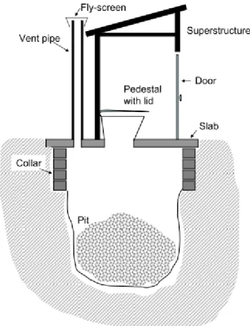
Figure 2-1: Ventilated improved pit (VIP) latrine basic structure ... 11
Figure 2-2: FSM flow chart ... 15
Figure 2-3: Schematic of the LaDePa machine ... 18
Figure 2-4: Vertical flow constructed wetland ... 19
Figure 2-5: A direct solar dryer ... 27
Figure 2-6: Indirect solar dryer ... 28
Figure 2-7: Mixed solar dryer ... 29
Figure 3-1: Collection of samples during pit emptying ... 37
Figure 3-2: CFD simulation of the drying chamber with singular inlet without diffuser plate results ... 39
Figure 3-3: CFD simulation of the drying chamber with singular inlet with diffuser plate results ... 40
Figure 3-4: CFD simulation of the drying chamber with multi-inlet with diffuser plate results .. 41
Figure 3-5: CFD simulation of the drying chamber with multi-inlet without diffuser plate results ... 41
Figure 3-6: Control system computer interface ... 44
Figure 3-7: Control system ... 44
Figure 3-8: Flow chart schematic of solar drying rig ... 45
Figure 3-9: Solar drying rig set-up ... 45
Figure 4-4: Mass ratio variation as a function of time during the solar drying of FS at 60 mm cross-sectional surface diameter, 5 mm thickness and 0.5 m/s air flow rate without applying air preheating under sunny, cloudy and overcast conditions ... 54
Figure 4-5: Mass ratio variation as a function of time during the open air sun drying of FS at 60 mm cross-sectional surface diameter, 5 mm thickness and 0.5 m/s air flow rate without applying air preheating under sunny, cloudy and overcast conditions ... 54
Figure 4-6: Sunny, cloudy and overcast conditions solar irradiance at the site and test period ... 55
Page | xii Figure 4-7: Sunny, cloudy, overcast conditions - surface and core temperatures at 60 mm cross-
sectional surface diameter, 5 mm thickness and 0.5 m/s air flow rate without applying air preheating ... 56 Figure 4-8: Sunny, cloudy and overcast conditions - ambient and chamber temperatures at 60
mm cross-sectional surface diameter, 5 mm thickness and 0.5 m/s air flow rate without applying air preheating ... 57 Figure 4-1: Mass ratio variation as a function of time during the open air sun and solar drying of
FS at 60 mm cross-sectional surface diameter, 5 mm thickness and 0.5 m/s air flow rate without applying air preheating under sunny conditions ... 58 Figure 4-2: Mass ratio variation as a function of time during the open air sun and solar drying of
FS at 60 mm cross-sectional surface diameter, 5 mm thickness and 0.5 m/s air flow rate without applying air preheating under cloudy conditions ... 59 Figure 4-3: Mass ratio variation as a function of time during the open air sun and solar drying of
FS at 60 mm cross-sectional surface diameter, 5 mm thickness and 0.5 m/s air flow rate without applying air preheating under overcast conditions ... 59 Figure 4-9: 5 mm thickness - open air sun drying and solar drying at 60 mm cross-sectional
surface diameter, sunny conditions and 0.5 m/s air flow rate without applying air preheating ... 60 Figure 4-10: 10 mm thickness - open air sun drying and solar drying at 60 mm cross-sectional
surface diameter, sunny conditions and 0.5 m/s air flow rate without applying air preheating ... 61 Figure 4-11: Open air sun drying thickness variation at 60 mm cross-sectional surface diameter
and sunny conditions ... 61 Figure 4-12: Solar drying thickness variation at 60 mm cross-sectional surface diameter, sunny
conditions and 0.5 m/s air flow rate without applying air preheating ... 62 Figure 4-14: 5 mm and 10 mm - core and surface temperatures at 60 mm cross-sectional surface
diameter, sunny conditions and 0.5 m/s air flow rate without applying air preheating ... 63 Figure 4-15: 60 mm surface diameter - open air sun drying and solar drying at 5 mm sample
thickness, sunny conditions and 0.5 m/s air flow rate without applying air preheating ... 64 Figure 4-16: 120 mm surface diameter - open air sun drying and solar drying at 5 mm sample
thickness, sunny conditions and 0.5 m/s air flow rate without applying air preheating ... 64
Page | xiii Figure 4-17: Surface area sun drying variation at 5 mm sample thickness and sunny conditions 65 Figure 4-18: Surface area - solar drying variation at 5 mm sample thickness, sunny conditions
and 0.5 m/s air flow rate without applying air preheating ... 66 Figure 4-19: Surface area surface and core temperatures at 5 mm sample thickness, sunny
conditions and 0.5 m/s air flow rate without applying air preheating ... 66 Figure 4-20: Air flow velocity solar drying variation at 5 mm sample thickness, sunny conditions and 60 mm cross-sectional surface diameter without applying air preheating ... 67 Figure 4-22: Air flow rate core and surface temperatures at 5 mm sample thickness, sunny
conditions and 60 mm cross-sectional surface diameter without applying air preheating ... 68 Figure 4-23: Air preheating sun drying variation at 5 mm sample thickness, sunny conditions and
60 mm cross-sectional surface diameter ... 69 Figure 4-25: Air preheating surface and core temperatures at 5 mm sample thickness, sunny
conditions and 60 mm cross-sectional surface diameter ... 70 Figure 4-26: Moisture content of FS after solar and open air sun drying under varying drying
conditions including the raw FS (prior to drying) ... 72 Figure 4-29: Ash content values of FS after solar and open air sun drying under varying drying
conditions including wet FS prior to drying ... 73 Figure 4-27: Shrinkage of FS after solar and open air sun drying at different experimental
conditions ... 74 Figure 4-28: Density values of FS after solar and open air sun drying under varying drying
conditions including wet FS prior to drying ... 75 Figure 4-30: Thermal conductivity values of FS after solar and open air sun drying under varying drying conditions including wet FS prior to drying ... 77 Figure 4-31: Heat capacity values of FS after solar and open air sun drying under varying drying
conditions including wet FS prior to drying ... 78 Figure 4-32: Calorific values of FS after solar and open air sun drying under varying drying
conditions including wet FS prior to drying ... Error! Bookmark not defined.
Figure 4-33: Orthophosphates, nitrates and ammonium ... Error! Bookmark not defined.
Figure 4-34: Carbon, nitrogen and sulphur ... Error! Bookmark not defined.
Page | xiv
LIST OF TABLES
Table 2-1: Fill up rates of pit latrines... 12
Table 2-2: Characteristics of clean FS from pit latrines ... 13
Table 2-3: Characteristics of wet human excreta ... 14
Table 2-4: Characteristics of dried FS samples ... 14
Table 2-5: Thermal characterisation of wet and dry VIP FS ... 15
Table 2-6: Selection matrix for FS treatment methods based on existing constraints ... 20
Table 3-2: Summary of drying conditions ... 47
Table 3-3: Summary of characterisation tests of the dried FS categorised into quantitative properties and qualitative observations ... 48
Table 4-1: Reference of the samples as a function of the conducted test ... 71
Table 4-2: Quantitative analysis of colour variation, crust, cracks and odour of the open air sun dried and solar dried FS samples ... 79
Page | 1
CHAPTER 1: INTRODUCTION
This section looks into the background of the study, covers the aim, scope, general and specific objectives of the research and an outline of the dissertation.
1.1 Background of the study
At the independence of the Republic of South Africa, according to a report by the Department of Water Affairs (2012), more than 20 million people (more than 50 % of the population of the state) did not have access to basic sanitation. This was due to the lack of development during the apartheid era (Mnisi 2011). According to the United Nations Development Goals and Sustainable Development Goals (SDGs), access to water and basic sanitation have been declared as basic human rights (Corcoran 2010; Sachs 2012).
Over the years, governments and organisations have moved to make provision for sanitation systems through standardised policies and guidelines (Still, Foxon et al. 2012). Though there has been an improvement in access to sanitation, the joint monitoring programme implemented for water supply and sanitation estimated that internationally in 2015 approximately 2.5 billion people did not have access to improved sanitation systems and resorted to the use of primitive sanitation systems and open defecation, the greater population being reported in Asia and sub-Saharan Africa (two-thirds and a quarter respectively) (Winker, Vinnerås et al. 2009; Freeman, Ogden et al. 2013;
Udert, Buckley et al. 2015; WHO 2015) .
Improved sanitation systems are classified in terms of storage of waste material, being described as either off-site or on-site sanitation systems. Off-site sanitation systems are systems in which the faecal sludge is collected from the individual sanitation systems and carried away from the site to be treated and disposed of. On-site sanitation systems are sanitation systems in which the safe disposal of FS takes place on or near the site of the toilet. On-site sanitation systems include ventilated improved pit latrines (VIP latrines), septic tanks and urine diversion (UD) toilets. These kinds of sanitation systems are the most commonly used across the world (Austin and Van Vuuren 2001; Langergraber and Muellegger 2005; Mnisi 2011; Bakare, Foxon et al. 2012). Sanitation systems can also be classified based on water usage and/or single or communal use.
Page | 2 VIP latrines are an improvement on basic latrine systems because of the introduction of a vent pipe fitted with a fly screen at the top to assist in the reduction of odours and trapping of insects from entering and/or leaving the latrine (Buckley, Foxon et al. 2008; Still, Foxon et al. 2012). These latrines provide the basic requirements for improved sanitation and have been the basic standard of sanitation provision in South Africa. As a result, the eThekwini municipality has provided over 60 000 VIP latrines since 1999 (Brouckaert, Foxon et al. 2013). As with all on-site sanitation systems, due to usage VIP latrines fill-up, it was reported that by 2009, 10 years later, 35 000 latrines were full and were emptied by the municipality (Still, Foxon et al. 2012).
Due to the nature and volume of faecal sludge from VIP latrines, there are difficulties in its safe disposal (Still, Foxon et al. 2012). Initial disposal options were the use of disposal in trenches or into wastewater treatment plants (WWTP) (Arlabosse, Chavez et al. 2004; O’Riordan 2009; Rose, Parker et al. 2015). This proved to be hazardous to the environment as the sludge was disposed of untreated and resulted in shock loading of wastewater treatment plants, respectively. As with animal excreta, faecal sludge has significant valorisation potential, it contains most of the nutrients needed for crop production and soil rejuvenation. These can be recycled through treatment systems and be used to reduce the use of non-renewable chemicals in chemical fertilisers (Malkki 1999;
Sharma Sunil 2013; Rose, Parker et al. 2015). Other potential uses of FS include the production of biogas, and as animal feed, with ongoing research into the application of FS as a fuel (Langergraber and Muellegger 2005; Fytili and Zabaniotou 2008; Muspratt, Nakato et al. 2014; Rose, Parker et al. 2015).
A number of treatment systems have focussed on the safe disposal of FS, including the use of drying beds and the black solder fly. The eThekwini municipality resorted to the use of the latrine dehydration and pasteurization machine (LaDePa) which produces dried and pasteurised pellets from the FS which can be utilised as a fertiliser and soil conditioner.
Drying is the removal of moisture from a substance, which allows for a significant reduction in the mass and volume of the substance, resulting in the reduction in costs associated with packaging, storage and transportation (Okos, Narasimhan et al. 1992). Examples of conventional drying techniques include mechanical dewatering, freeze drying, radiative drying and hot air convective drying, but these are expensive and energy intensive with most of them dependent on unrenewable sources of energy.
Page | 3 The United Nations Development Program (2000), Goldemberg (2000) and Banerjee (2005) reported that 80% of the world’s total energy requirements emanate from fossil fuels with renewable energy sources accounting for only 2 % to 3 %, highlighting the need for a transition to renewable energy systems. Over 40 % of industrial use of energy is directed towards heating applications.
Drying of moist materials involves simultaneous heat and mass transfer phenomena, which take place inside the material being dried, as a result making it a complex process (Perumal 2007).
Drying kinetics are affected by humidity, air temperature, size of material and air flow rates (Kiranoudis, Maroulis et al. 1992, Kamwere 2017).
Solar thermal energy is a renewable energy option with vast potential due to its abundance, inexhaustibility and non-polluting nature (Basunia and Abe 2001). The gradual reduction in the costs of solar collectors coupled with the increase in environmental pollution concerns and increase in costs of fossil fuels, have resulted in the increase of the feasibility studies of solar drying. Solar drying refers to the use of solar thermal energy for drying operations in controlled conditions with the application of scientific data whereas sun drying refers to the uncontrolled use of direct sunlight for drying. A variety of solar drying technologies have been used for various applications, such as greenhouse, box and tent designs (Mühlbauer Esper et al.). These differ due to the variation in solar intensities experienced in different locations (Bahnasawy and Shenana 2004).
Solar dryers have acquired a high footprint in the drying of biological products, mainly agricultural produce, as they provide protection of the substance from the environment, and provide a controlled environment which results in higher drying rates compared to sun drying technologies in which the environment is not controlled (Hossain and Bala 2002). Solar dryers are cost efficient because they use simple designs and are relatively cheap to build and operate. They offer an effective alternative technology for drying FS.
Several solar dryers have been reviewed by Perumal (2007) and Ekechukwu and Norton (1999) for commercial use, who concluded that forced convection dryers provide better control of the drying air, but require more energy. Diamante and Munro (1993) concluded that solar drying produces better quality product than open air sun drying. Prakash, Jha et al. (2004) and Kumar, Hebbar et al. (2006) have expressed concern that the high drying temperatures in solar dryers may cause damage to the quality of the dried product, therefore require constant monitoring.
Page | 4 Drying of FS using solar thermal energy offers an alternative method to the energy intensive treatment processes of FS, such as LaDePa. Drying of FS before reuse is a critical treatment step and is traditionally performed through the use of open air-sun drying technologies, such as drying beds in most developing countries. Use of drying beds faces the drawbacks of land requirements and lengthy drying times (Seck, Gold et al. 2015).
Although literature is available on the properties of FS, there is poor literature on the conventional and infrared drying of FS, no information is available on the drying kinetics of FS with respect to solar energy. This study is focused on characterising the solar drying characteristics of FS from VIP latrines in the eThekwini municipality through the analysis of the drying of FS in a custom designed solar dryer. This research work in the use of solar energy in FS treatment will assist in the efficient design and optimisation of solar energy based treatment methods. Figure 1-1 is a flow chart which describes the possible uses of excreta and highlights the criticality of drying in processes related to resource recovery.
Page | 5
Figure 1-1: Flow Chart indicating the possible uses of excreta and highlighting the criticality of drying (PRG 2017) Source: (Pollution Research Group 2017)
Page | 6 1.2 Aim of the study
The aim of this study is to characterise FS drying using solar thermal energy as solar drying is a promising alternative for FS treatment but there is lack of scientific data regarding the use of solar thermal energy. The data and knowledge generated will be useful for sanitation practitioners interested in the solar processing of faecal sludge for the improvement of the existing technologies designs or the development of technological innovations.
1.3 Scope of the study
The research will utilise FS sampled randomly from the pit emptying process of the eThekwini municipality of VIP latrines. Parameters applied in the investigation include the effects of varying weather conditions, airflow velocity, air preheating temperature, cross-sectional surface area, and sample thickness. The parameters were investigated for solar drying as well as open air sun drying.
The dependence on prevailing weather conditions, affected the repeatability of the experiments.
Thermal properties, nutrient concentration and physical properties of the dried samples were analysed
1.4 Objectives
1.4.1 General objectives
To evaluate the drying characteristics of FS sampled from ventilated improved pit (VIP) latrines in a custom designed solar drying system and to evaluate the effect of drying conditions on the properties of FS.
1.4.2 Specific objectives
To design and build a solar dryer.
To evaluate the effect of weather conditions, air flowrates, air temperature, geometry of sample and size of sample on drying rates as these are critical to drying times.
To evaluate physico-chemical properties of the dried products, namely ash and moisture content, nutrient effects, density, shrinkage, calorific and thermal conductivity values as these are critical for the reuse of FS.
Page | 7
To evaluate the qualitatively the effects of drying on the product, namely formation of a odours, crust and cracks as these are critical to both drying times and reuse requirements.
1.5 Outline of dissertation Chapter 1 - Introduction
Introduces the study, providing the aim, scope and the objectives of the study.
Chapter 2 - Literature review
Provides a literature review on sanitation systems, paying particular focus to ventilated improved pit (VIP) latrines and its content, together with the associated management and resource recovery of FS. It also looks into drying technologies, with a particular focus on solar drying technologies as well as the drying concepts.
Chapter 3 - Materials and Methods
Explains the experimental apparatus and methods employed in the study to fulfil the objectives (of the study. The parameters used for the data analysis are also described. The chapter provides an insight into the design and commissioning of the rig and simulations for the design.
Chapter 4 - Results and discussion
Presents the major results and the subsequent discussion. The main trends deducted from the results are highlighted.
Chapter 5 - Conclusion and recommendations
The results are summarised and various conclusions drawn from the study are presented. The limitations of the current study and recommendations are provided.
Page | 8
CHAPTER 2: LITERATURE REVIEW
This chapter details the review of the relevant literature in order to understand the theoretical knowledge and state-of-art to achieve the desired goals. Individual aspects pertaining to the
research study, namely, sanitation systems, ventilated improved pit (VIP) latrines and management of FS from VIP latrines, are presented and discussed. Solar energy and conventional drying technologies are addressed, followed by a review of solar drying technologies, drying concepts and the property and material related factors affecting solar
drying of FS.
2.1 Faecal sludge (FS)
“Faecal sludge is the crude or partially processed, semisolid or slurry, coming about because of the gathering, stockpiling and treatment of black water and excreta from sanitation units, with or without greywater” (Strande and Brdjanovic 2014). FS contains all the contents of pits and vaults which gather faecal material in on-site sanitation establishments.
2.1.1 Sanitation systems
Sanitation systems are responsible for the capture, storage, treatment and disposal or reuse of human waste and wastewater. There are a variety of sanitation technologies available today. The variations result in a difference in convenience for the user, protection against the propagation of diseases, and water requirements during operation and use. As a consequence, sanitation technologies can be categorised in various ways. The main categories are:
Waste disposal
Water use
Individual or communal use
Page | 9 2.1.1.1 Waste disposal
Sanitation systems can be categorised based on the manner of the disposal of waste material, which can either be related to the on-site technology or to the transport of the material to a different location. Thus, sanitation technologies can be divided into two categories:
On-site sanitation systems
Off-site sanitation systems
On-site sanitation systems dispose the waste on or close to the location of the sanitation system.
On-site sanitation systems arise from the inability to transport or dispose of the waste away from the system. They are advantageous in providing improved sanitation systems at low costs. The major setbacks are the contamination of the environment, bad odours and insect breeding sites with the potential for collapse of the toilet structure. Septic tanks, latrines, including simple or traditional latrines and ventilated improved pit (VIP) latrines, are examples of on-site sanitation systems.
Off-site sanitation systems are sanitation technologies in which the waste is collected from the individual sanitation systems and carried away from the site to be treated and disposed of. These are normally connected to sewer networks and wastewater treatment plants (WWTPs). Sewer systems and bucket latrines are examples of off-site sanitation systems.
2.1.1.2 Water use
Sanitation systems can be categorised based on water usage. These can either be wet systems or dry systems. Dry sanitation systems do not utilise water as a carrier and the waste is broken down by anaerobic methods, through decomposition and/or dehydration. Wet sanitation systems utilise water to treat and transport the waste. VIP latrines fall under dry sanitation systems as no water is added to the system.
Page | 10 2.1.1.3 Individual or communal use
Sanitation systems can also be categorised through their application as either individual household or community sanitation systems. Sanitation systems classified under household sanitation systems include pit latrines, pour flush toilets as well as septic tanks which are built for use by an individual household. Systems such as communal toilets, bucket latrines and sewerage systems are classified as community sanitation facilities. VIP latrines can either be individual household or communal depending on application.
2.1.2 Ventilated improved pit (VIP) latrines
VIP systems are dry sanitation technologies, hence not requiring water input, and have been accepted as the standard for basic sanitation in South Africa (Buckley, Foxon et al. 2008).
2.1.2.1 Description of ventilated improved pit latrines (VIP latrines) and contents
VIP latrines are an improvement on standard/basic pit latrines. They are designed to reduce foul odours and the quantity of insects, e.g. flies, within the enclosure of the toilet. There are certain requirements for basic pit latrines to be qualified as a VIP latrine (Buckley, Foxon et al. 2008). A VIP latrine must:
i. Provide separation of waste from the users in a hygienic manner ii. Include a ventilation pipe with a fly screen at the top-end
iii. Must be constructed on a secure slab iv. Must be private and dignified for the user
A standard VIP latrine comprises the pit, cover slab, superstructure, vent pipe with fly screen, pedestal, lid, roof and superstructure door (Buckley, Foxon et al. 2008). Figure 2-1 shows the basic structure of a VIP latrine.
Page | 11
Figure 2-1: Ventilated improved pit (VIP) latrine basic structure Source: Buckley, Foxon et al. (2008)
The components of the VIP latrine are explained as follows:
Pit – the main purpose of the pit is the collection of the waste, it can be a single or twin pit with an open-top brickwork or blockwork. It should also be lined to avoid collapse.
Cover slab – made from reinforced concrete with two openings for the pedestal and vent pipe.
Superstructure – to provide privacy and weather protection. Can be made from the same build work as the house attached to the latrine.
Vent pipe inclusive of fly screen – to control odours as well as insects such as flies. The pipe extends at least 500 mm above the roof of the toilet.
Pedestal, lid, roof and superstructure door – to provide decency and privacy to the user.
Page | 12 There are several processes occurring in a VIP latrine. These include: gradual fill-up with faecal matter, water and other waste material, water transfer both into and out of the pit, as well as biological and physico-chemical transformations. Substantial volume reduction occurs though natural processes, such as anaerobic digestion, which slows down the fill-up rate but does not stop waste build-up (Buckley, Foxon et al. 2008). Table 2-1 shows the average fill up rates of pit latrines in different conditions of use.
Table 2-1: Fill up rates of pit latrines based on conditions present in the pit
CONDITIONS PRESENT IN PIT RATE OF SLUDGE ACCUMULATION (l/year.person) Waste retained in water where degradable anal cleansing
materials are utilised
40 Waste retained in water where non-degradable anal cleansing
materials are utilised
60 Waste retained in dry conditions where degradable anal
cleansing materials are utilised
60 Waste retained in dry conditions where non-degradable anal
cleansing materials are utilised
90 Source: Franceys, Pickford et al. (1992)
Pit contents are mainly composed of faeces, urine and biodegradable waste matter. Users also tend to use the pit as a waste/refuse disposal option resulting in the collection of non-biodegradable matter in the pit. The content varies within an individual pit and between various pit latrines. These variances include variation in appearance, chemical and physical characteristics. These differences are predominantly due to differences in user practises and geographical properties.
2.1.2.2 Physical and chemical characteristics of faecal sludge (FS) from VIP latrines There are various ways to analyse and characterise FS. Buckley, Foxon et al. (2008) analysed FS from VIP latrines according to chemical oxygen demand (COD), biodegradability, characterisation of the solids, anaerobic and methanogenic activity.
Table 2-2 shows the average values of the characterisation of VIP FS from the study. The analysis was conducted on clean FS, which refers to FS that has been screened and sieved to remove all non-biodegradable matter.
Page | 13
Table 2-2: Characteristics of clean FS from pit latrines
ANALYSIS AVERAGE VALUE UNIT
Total COD 105 mg/g wet weight
Total COD 445 mg/g dry weight
Soluble COD 31 % of total COD
Moisture content 76 % of wet sample
Total solids 33 % of wet sample
Organic solids 36 % of solids
Inorganic solids 64 % of solids
Soluble nitrates 0.028 mgN/g wet sample
Source: Buckley, Foxon et al. (2008)
FS, similar to animal excreta, is rich in nutrients. These nutrients can be utilised to supplement or substitute synthetic fertilisers. The nutrients can be water soluble or insoluble. Zuma, Velkushanova et al. (2015) analysed the chemical and thermal properties of FS from ventilated improved pit latrines within the eThekwini municipality. Properties analysed included moisture content, ammonia, total Kjeldahl nitrogen (TKN), orthophosphates, thermal conductivity and calorific values. Moisture content varied in terms of position in the pit, with 60 % to 70 % recorded at the bottom and 80 % to 90 % recorded at the top (Bakare, Foxon et al. 2012; Zuma, Velkushanova et al. 2015). The moisture content differs with height but is constant with horizontal position. TKN varied between 4 mg/g to 14 mg/g of wet sludge, ammonia recorded a maximum value of 5.87 mg/g of wet sludge to a minimum of 0.1 mg/g of wet sludge. Orthophosphates were found to be lower than 0.06 mg/g of wet sludge. Thermal conductivity values ranged between 0.51 W/m.K and 0.59 W/m.K and calorific values between 0.0029 MJ/g and 0.0238 MJ/g of dry sludge (Zuma, Velkushanova et al. 2015).
In summary, although moisture content showed variation as a function of the height in the pit, such variances were not noticed for the nutrient concentrations, thermal conductivity and calorific values.
Page | 14 Table 2-3 shows a summary of other research work on wet human excreta (wet refers to the samples not being exposed to drying before analysis).
Page | 15
Table 2-3: Characteristics of wet human excreta
PARAMETER SOURCE
(Nwaneri 2009) (Gantzer, Henny et al.
2002)
(Lopez Zavala, Funamizu et al. 2002)
(Almeida, Butler et al.
1999)
Moisture content 78% - 81.8% 79.2%
Total solids 22% - 18.2% 20.8%
Volatile solids - - 84.4% -
Total COD 1.11mg/mg 0.57mg/mg 1.45mg/mg 1.38mg/mg
Dissolved COD 0.37mg/mg 0.09mg/mg - -
Suspended COD 0.67mg/mg 0.46mg/mg - -
Volatile fatty acids - 8.46 gCOD/l - 1.5gCOD/l
Total nitrogen - 17.82mg/g 60.1mg/g -
Ammonia-nitrogen - - 3.4mg/g 7.2mg/g
Nitrate-nitrogen - - 0.03mg/g 0.14mg/g
pH - - 7.5 -
Sulphate ions - - 1.1mg/g -
Chloride ions - - 4.2mg/g -
Nutrient capacity of FS after treatment is critical for resource recovery as a fertiliser or soil conditioner. Mnkeni and Austin (2009), Nikiema, Cofie et al. (2013), and Komakech, Banadda et al. (2014) analysed the nutrient concentration in dried FS samples. Parameters analysed included phosphorus, potassium, calcium, magnesium, orthophosphates and nitrates. Mirara (2017) and Makununika (2016) analysed similar nutrients using samples from VIP latrines in the eThekwini municipality. Table 2-4 shows a summary of the results from their findings.
Table 2-4: Characteristics of dried FS samples
NUTRIENT SOURCE
(Makununika 2016)
(Mirara 2017) (Komakech, Banadda et al.
2014)
(Nikiema, Cofie et al.
2013)
(Mnkeni and Austin 2009) (mg/kg dry solid) (mg/kg dry
solid)
(mg/kg dry solid) (mg/kg dry solid) (mg/kg dry solid)
P 7.2 6.0 2.7 12.4 3
K 8.6 8.0 19.5 6.1 4.4
Ca 42.1 35 - - 4
Mg 11.2 12.5 - - 7.9
PO43- 2.3 5.0 0.37 - -
NO3- 0.5 0.3 - 2.9 -
NH3 4.5 5.0 - - -
Page | 16 Thermal characterisation of FS is critical for the design and building of treatment facilities. Table 2-5 shows a summary of the results of the studies of Zuma, Velkushanova et al. (2015), Makununika (2016) and Mirara (2017). The volatile solids were found to greatly affect calorific values (Makununika 2016). Thermal conductivity showed a high dependence on the moisture content of the sludge (Makununika 2016; Mirara 2017; Zuma, Velkushanova et al. 2015).
Table 2-5: Thermal characterisation of wet and dry VIP FS
PROPERTY SOURCE
(Makununika 2016) (Mirara 2017) (Zuma, Velkushanova et al. 2015)
Calorific value 12.5MJ/kg (w.b) 15-25MJ/kg(d.b) 4.9-19.3MJ/kg (d.b)
Thermal conductivity 0.044W/m.K (w.b) 0.06W/m.K (w.b) 0.42-0.59W/m.K (w.b)
Heat capacity 220J/kg.K (w.b) 400J/kg.K (w.b) 1.87-4.73kJ/kg.K(w.b)
Ash content - 30% (d.b) -
Volatile solids 0.47g/g (d.b) 70% (d.b) 0.45-4.3gVS/g ash
d.b-dry basis, w.b-wet basis, VS-volatile solids
2.1.2.3 Management, treatment and resource recovery from ventilated improved pit (VIP) latrine faecal sludge (FS)
Figure 2-2: FSM flow chart
FS starts as an unavoidable waste resulting from the use of pit latrines. The present management systems of FS has been fragmented and improper with attendant poor health and environmental problems. Figure 2-2 shows a FSM flow chart.
Page | 17 Due to the nature of FS, it can be utilised for various applications. The difficulty in promoting these applications is mainly due to the view of FS as waste and not a resource for harnessing. The design of FS management systems for resource recovery can lead to the development of viable business models (Diener, Semiyaga et al. 2014). FS can be utilised as a combustion fuel, for production of biogas as a result of anaerobic digestion, for derivation of protein for use as animal feed or as an organic fertiliser and for soil conditioning (Muspratt, Nakato et al. 2014; Werther and Ogada 1999; Čičková, Newton et al. 2015;, Vinnerås, Palmquist et al. 2006; Moe and Rheingans 2006; Mihelcic, Fry et al. 2011; Malkki 1999; Niwagaba 2007).
Traditional disposal methods of VIP FS include the covering up of the full pit and construction of a new one, or emptying of the pit and disposal of the FS in an off-site facility. Still, Foxon et al.
(2012) lists alternatives such as burial in an on-site pit, anaerobic digestion to produce biogas, treatment in a wastewater treatment plant (WWTP), use of the black solder fly, deep row entrenchment and composting. Williams (2013) suggested the recovery of energy through thermochemical processes such as pyrolysis, combustion and gasification. Sevilla and Fuertes (2009) suggested the use of anaerobic digestion to produce methane and recoup biogas, but this requires the addition of water which is counterproductive as it is easier to handle, transport and dispose of dry materials.
FS has different properties to sewage sludge; FS is 10 to 100 times more concentrated than sewage sludge; 1.5 m3 of FS is approximately equivalent to 1000 m3 of sewage sludge, which is mainly due to the lack of water content in FS. FS has non-biodegradable material in it due to the use of the pit as a disposal option. As a result, disposal into wastewater treatment plants causes shock loading to the wastewater treatment plant system (Still, Foxon et al. 2012).
Wastewater treatment plant sludge (biosolids) has been applied as an alternative fuel source in Europe and the US for the cement industry (Boesch and Hellweg 2010). Technical viability for the application of FS as a fuel has been demonstrated through laboratory and pilot scale research in Dakar, Senegal, and Kampala, Uganda (Gold, Niang et al. 2014). The average calorific value of FS is 17 MJ/kg (Muspratt, Nakato et al. 2014) compared to 8 MJ/kg to 23 MJ/kg for biosolids (Modinger and Mayr 2006; Spinosa and Vesilind 2001). For combustion resource recovery, sludge should be dried to a minimum of 28 % moisture content (Muspratt, Nakato et al. 2014).
Page | 18 Deep row entrenchment is the burying of FS in 20 m long, 0.6 m wide and between 1.2 m to 1 m deep trenches. This results in an improved soil fertility as FS acts as a slow release fertiliser. This has massive benefits for the agroforestry sector as it increases the growth rates of the trees and helps in the recovery of wasteland such as mine spills (Still, Foxon et al. 2012). A drawback is that FS is biological waste that then requires the addition of disinfectants and antibacterials as it might contain harmful pathogens.
FS waste can also be incinerated to reduce the volume, form charcoal and tar, and the resultant ash will be buried in landfill sites. This is achieved through pyrolysis and gasification. Pyrolysis is the degradation of organic waste thermally without oxygen to produce carbonaceous charcoal, tar and combustible gases. Gasification is the thermal degradation of organic waste in the context of a limited supply of oxygen and in the presence of steam or carbon dioxide to produce tar, ash and a gaseous fuel composed mainly of hydrogen and carbon monoxide (Williams 2013).
Creation of biogas from FS is through anaerobic digestion. Small scale digesters utilising human excreta and animal waste as feed are in use in Ghana (Box 2010). Anaerobic digesters are mainly applied for wastewater treatment with research currently being conducted to access the feasibility for adoption of anaerobic digesters for FS treatment.
Hydrothermal carbonisation is the process in which organic material is decomposed in water at temperatures between 150 °C and 350 °C to form a high carbon content product (Sevilla and Fuertes 2009). Supercritical water oxidation utilises water at temperatures and pressures above 374 °C and 221 bar to decompose organic compounds which enables energy recovery while an organic stable material is produced (Gidner, Stenmark et al. 2001; Veriansyah and Jae-Duck 2007).
Page | 19 FS can be applied as feed stock to insect larvae for protein generation as animal feed. Agriprotein applies the black soldier fly larvae (BSFL) to treat and process FS for the production of chicken and/or fish feed (Van Huis, Van Itterbeeck et al. 2013). This follows on from insect larvae being widely cultivated for animal feed in aquaculture, frog and chicken farms utilising municipal waste as feed (Calvert, Martin et al. 1969; Hem, Toure et al. 2008; Ogunji, Nimptsch et al. 2007; St‐
Hilaire, Sheppard et al. 2007). Application of BSFL is an example of conversion of organic refuse by saprophages (CORS) technology. The larvae feed on organic material and can be applied to the treatment of FS. Resource recovery occurs during the harvesting of the prepupae as they migrate from the feedstock to pupate. The prepupae contain 44% crude oil and 33% fat, so can be applied as animal feed and for biodiesel production (St‐Hilaire, Sheppard et al. 2007).
Thermal drying can be utilised on faecal sludge, a example is the latrine dehydration and pasteurization machine (LaDePa). LaDePa is used to process FS into pasteurised dry pellets. The resulting pellets can be utilised in agricultural crop production or as a fuel (Harrison and Wilson 2012). Figure 2-3 shows the schematic of the LaDePa. The machine applies infrared radiation to dry and pasteurise FS pellets using medium infrared radiation lamps. Tests performed on the LaDePa machine have demonstrated the efficient deactivation of Ascaris eggs present in FS.
Figure 2-3: Schematic of the LaDePa machine Source: Harrison and Wilson (2012)
Page | 20 The application of drying beds in FS management is as a treatment method aimed mainly at dewatering the FS. The age of FS and the period of on-site storage have an effect on the ability to dewater as it affects the stability of the sludge (Singh, Mohan et al. 2017). Drying beds can either be unplanted or planted drying beds. Unplanted drying beds utilise shallow beds which are filled with sand and gravel, and fitted with an underdrain to collect the resulting leachate. The leachate requires further treatment before disposal and/or resource recovery as it still contains pathogens (Cofie, Agbottah et al. 2006).
A planted drying bed, also known as a vertical-flow constructed wetland, applies the use of emergent plants such as Andropogon gayanus to treat the FS (Joceline, Koné et al. 2016). The emergent plants are critical to the operation of planted drying beds in regards to waste stabilisation and pathogen reduction (Strauss, Larmie et al. 1997). Advantages of drying beds include low cost, good dewatering efficiency, no energy requirements, cost effectiveness, ease of operation and ability to handle high loading rates. The disadvantages include high labour intensity, limited pathogen reduction, high land requirements and the need for post treatment. Figure 2-44 shows the scheme of a basic vertically constructed wetland.
Figure 2-4: Vertical flow constructed wetland Source: Tilley (2008)
Table 2-6 show a selection matrix for FS treatment methods based on existing constraints at the treatment site, highlighting dependence on CAPEX, OPEX, skill, land and energy requirements and indicating capacity for resource recovery.
Page | 21
Table 2-6: Selection matrix for FS treatment methods based on existing constraints
TREATMENT METHOD CONSTRAINTS
Land requirement
Energy requirement
Capital expenditure
Operation expenditure
Skill requirement
Resource recovery
Unplanted drying bed H L L L L M
Planted drying bed H L L L L M
Centrifugation L H H H M L
Settling-thickening tank L L L L L M
Imhoff tank L L M M H M
Geobag H L M M L L
Co-composting H L H H L H
Deep row entrenchment H L L L L L
Vermicomposting H L H H M H
Anaerobic digester L L H H H M
Shallow trenches H L L L L L
Solar sludge oven L L M L M H
Black solder fly larvae (BSFL)
H L H H M H
Solar drying H L M M M H
H-high, M-medium, L-low
Source: Harrison and Wilson (2012)
2.2 Solar energy
Globally, many countries have begun to address the challenge of sustainable energy application through adjustments of energy consumption methods with the goal to uphold social, ecological and financial components of sustainable development. Energy solutions based on fossil fuels such as oil, coal and natural gas have resulted in an increase of the amount of greenhouse gases released into the atmosphere. Fossil fuel deposits are also in course of depletion, which will result in exorbitant operation costs for energy dependent processes which depend on fossil fuel energy. The earth receives more energy from solar irradiance in 1 hour than the yearly energy requirements (Thirugnanasambandam, Iniyan et al. 2010).
There is growing interest in alternative sources of energy, such as solar and wind energy, in both the developed and developing countries (Power 2010). Solar energy is a highly promising renewable energy resource for the generation of power. Solar energy represents the largest energy inflow into ecosystems. After reflection and absorption in the atmosphere, a significant amount of solar energy is received on the earth’s surface and utilised for the development of living organisms (Bosshard, Hermann et al. 2006). As a green energy source, solar energy is environmentally friendly, as it possesses a low carbon footprint as well as low pollutant emissions.
Page | 22 Despite the availability and capacity of solar resource with potential to supply energy on a global scale, generation of solar energy based power is still low compared to other energy resources. The main constraints have been due to the relatively high capital cost required to implement solar systems, although solar energy technologies used to harness solar energy are now becoming more cost effective. The intermittent nature of solar energy availability results in the requirement of energy storage systems and subsequently relatively low power density (Bosshard, Hermann et al.
2006).South Africa experiences, in average, over 2 500 hours of sunshine per solar year and solar irradiation at the surface ranges from 4.5 to 6.5 kWh/m2/day (Fluri 2009; Zawilska and Brooks 2011).
2.2.1 Types of solar energy systems
Solar energy systems can be classified according to two categories:
Thermal systems which convert solar energy into thermal energy
Photovoltaic (PV) systems which convert solar energy into electrical energy 2.2.1.1 Solar thermal systems
Solar thermal systems utilise solar radiation for thermal energy generation. The incident solar radiation can be collected and focused and collected by a variety of techniques (Alsharkawi and Rossiter 2016). Thermal power systems based on solar energy can be designed to satisfy demand during daylight hours and can be coupled with energy storage systems to ensure that their operation can be extended to 24 hours of operation while meeting the base load requirements (Chaanaoui, Vaudreuil et al. 2016). The excess heat collected during the system exposure to solar radiation can be stored in liquid, solid or phase changing media like molten salts, ceramics, concrete, and can then be utilised during periods where the solar radiation received is not sufficient to operate the required processes (Timilsina, Kurdgelashvili et al. 2012). There are different applications for thermal energy systems, for example generation of power, water heating in households, and cooking applications.
Page | 23 Solar thermal energy can be harnessed by solar thermal collectors or solar thermal concentration onto a focal point. The major component of any solar system is the solar collector. This is a device which absorbs the incoming solar radiation, converts it into heat, and transfers it to a fluid (usually air, water, or oil) flowing through the collector. Solar thermal concentration is the use of reflectors to focus solar irradiation to concentrate the energy received at the focal point. These systems can be merged so that the solar energy is focused onto the collector (Alsharkawi and Rossiter 2016).
2.2.1.2 Photovoltaic (PV) systems
Photovoltaic (PV) energy capture is the conversion of solar irradiance directly into electricity. PV systems directly convert solar radiation using specially designed cells (Maycock 2005). The intensity of the incident radiation determines the electricity produced. PV system cells are made of layers of semi-conductor material (Sahoo 2016). The costs of PV systems are currently declining due to the improvement in PV technology with continuous research and increase of efficiency (Tyagi, Rahim et al. 2013).
2.2.2 Drying
Drying is the removal of moisture from a substance to a desired level within a certain period of time (Ekechukwu and Norton 1999).
Drying is applied in various processes in the chemical, agricultural, pharmaceutical, mineral and wood processing industries (Mujumdar 2006). When a material is exposed to air at a particular temperature and humidity, the material will either gain or lose moisture until an equilibrium condition is achieved between the drying substance and the surrounding air (Coulson 1999). Two processes take place simultaneously during drying: heat transfer from the heat source to the sample (this can be through conduction, convection or/and radiation), and a mass transfer from the wet material to the surrounding air (Perumal 2007). During drying, the substance to dry tends to form a dry surface layer, a crust, which is resistant to moisture transfer if the drying rate is too high. As a result, to avoid this effect, the drying rate must be controlled to guarantee optimum rates (Arinze, Schoenau et al. 1979).
Page | 24 Drying is a highly energy intensive process. Several research works have been conducted to analyse possible energy alternatives and optimisation of current processes. The optimisation of dryers requires in-depth and complete knowledge and understanding of the drying process. Energy savings, improved product quality and avoidance of environmental pollution are possible through utilisation of renewable energy technologies (Icerman and Morgan 1984, Basunia and Abe 2001).
Use of renewable energy technologies to replace conventional energy systems has received increased attention recently due to their potential to meet the basic needs of many countries (Banerjee 2005).
2.2.2.1 Drying technologies
Methods of drying include open air sun drying, solar drying, radiative drying, hot air convective drying, oven drying and freeze drying.
2.2.2.1.1 Open air sun drying
Open air sun drying is the most common drying method applied in tropical and sub-tropical countries. It involves the laying out of produce in thin layers exposed to direct sun and wind (Mustayen, Mekhilef et al. 2014). Open air sun drying depends on the environmental conditions of solar irradiation, wind and other ambient conditions (Panwar, Kaushik et al. 2012). The advantages of open air sun drying include simplicity and low costs. The disadvantages of open air sun drying include the need for a large surface area, decreased product quality due to lack of environmental protection, uneven drying and it is highly labour intensive.
2.2.2.1.2 Radiative drying
The wavelength of waves utilised distinguishes microwave from infrared drying. Microwave drying utilises a wavelength between 0.025 microns to 0.75 microns, falling between radio and infrared waves. Thiagarajan (2008) reported a 75 % energy saving when applying microwave drying compared to traditional thermal drying techniques. Microwave electromagnetic radiation has the ability to penetrate within the solid exciting dielectric molecules and causing a temperature rise. This provides the required energy for the heat and mass transfer processes during drying.
Application of microwave radiation is common in food processing as it retains the texture and taste of food (Thiagarajan 2008).