CLOSED-LOOP CONTROL OF BUCK-BOOST CONVERTER USING THE PID CONTROLLER
by
ZEESHAN AHMAD (1732222493)
A dissertation submitted in partial fulfillment of the requirements for the degree of
Master of Science (Electrical Power Engineering)
School of Electrical System Engineering UNIVERSITI MALAYSIA PERLIS
2018
UNIVERSITI MALAYSIA PERLIS
NOTES : * If the thesis is CONFIDENTIAL or RESTRICTED, please attach with the letter from the organisation with the period and reasons for confidentiality or restriction. Replace thesis with dissertation (MSc by Mixed Mode) or with the report (coursework)
DECLARATION OF DISSERTATION
Author’s Full Name : ZEESHAN AHMAD
Title : CLOSED LOOP CONTROL OF BUCK-BOOST
CONVERTER USING THE PID CONTROLLER
Date of Birth : 10 OCTOBER 1984 Academic Session : 2018/2019
I hereby declare that this dissertation becomes the property of Universiti Malaysia Perlis (UniMAP) and to be placed at the library of UniMAP. This dissertation is classified as:
CONFIDENTIAL (Contains confidential information under the Official Secret Act 1997)*
RESTRICTED (Contains restricted information as specified by the organization where research was done)*
OPEN ACCESS I agree that my dissertation to be published as online open access (Full Text)I, the author, give permission to reproduce this dissertation in whole or in part for the purpose of research or academic exchange only (except during the period of _______ years, if so requested above)
Certified by:
SIGNATURE SIGNATURE OF SUPERVISOR
DY1157053 DR. MOHAMMAD FARIDUN NAIM
TAJUDDIN (NEW IC NO. /PASSPORT NO.) NAME OF SUPERVISOR
Date: 28 August 2018 Date: 28 August 2018
© This item
is protected
by original
copyright
ii
ACKNOWLEDGEMENT
I would like to thank my dissertation supervisor Dr. Mohammad Faridun Naim bin Tajuddin for the continuous support of my Master study and research, for his patience, motivation, and immense knowledge. His guidance helped me in all the time of research and writing of this dissertation.
I give deep thanks to the Professors and lecturers at the School of Electrical Systems Engineering, Universiti Malaysia Perlis (UniMAP). I would like to thank my friends for accepting nothing less than excellence from me.
Finally, I must express my very profound gratitude to my parents and to my brother for providing me with unfailing support and continuous encouragement throughout my study and through the process of researching and writing this dissertation. This accomplishment would not have been possible without them.
This thesis is heartily dedicated to my mother.
Thank you.
© This item
is protected
by original
copyright
iii
TABLE OF CONTENTS
PAGE
DECLARATION OF DISSERTATION i
ACKNOWLEDGEMENT ii
TABLE OF CONTENTS iii
LIST OF TABLES vii
LIST OF FIGURES viii
LIST OF ABBREVIATIONS x
LIST OF SYMBOLS xi
ABSTRAK xii
ABSTRACT xiii
CHAPTER 1 : INTRODUCTION 1
1.1 Introduction 1
1.1.1 Output Stability Control 3
1.2 Problem Statement 4
1.3 Objectives 4
1.4 Project Scope 4
1.5 Organisation of Chapters 5
CHAPTER 2 : LITERATURE REVIEW 7
2.1 Introduction 7
2.2 Buck Converter 8
2.2.1 Working Principle 8
2.2.1.1 During Closed Switch (ON) 9
© This item
is protected
by original
copyright
iv
2.2.1.2 During Opened Switch (OFF) 10
2.2.1.3 Output Voltage Ripple 12
2.3 Boost Converter 12
2.3.1 Working Principle 13
2.3.1.1 During Closed Switch (ON) 13
2.3.1.2 During Opened Switch (OFF) 14
2.3.1.3 Output Voltage 14
2.3.1.4 Output Voltage Ripple 16
2.4 Buck-Boost Converter 16
2.4.1 Introduction 16
2.4.2 Working Principle 18
2.4.2.1 During Closed Switch (ON) 18
2.4.2.2 During Opened Switch (OFF) 19
2.4.3 Output Voltage 21
2.4.4 Duty Cycle 21
2.4.5 Inductor Current and Voltage 22
2.5 Stability Control of the Buck-Boost Converter 22
2.5.1 Proportional Controller 23
2.5.2 Proportional Integral (PI) Controller 25
2.5.3 Proportional Integral Derivative (PID) Controller 25
2.5.3.1 How PID Controller Work 26
2.5.3.2 PID Transfer Function 28
2.5.3.3 Effects of Increasing the Different Parameters 29
2.6 Introducing the PID Tuning 29
2.6.1 Tuning Methods 31
© This item
is protected
by original
copyright
v
2.6.2 Introduction to the Ziegler-Nichols(Z-N) Tuning Method 32
2.6.2.1 Step Based Response Method 32
2.6.2.2 Frequency Based Response Method 34
2.6.2.3 Modified Ziegler-Nichols Tuning Method 35
2.7 Critical Review 37
2.8 Summary 43
CHAPTER 3 : METHODOLOGY 44
3.1 Introduction 44
3.2 Research Framework 44
3.3 Closed-Loop Feedback of DC-DC Buck-Boost Converter 45
3.4 Open-loop Transfer Function of System 47
3.4.1 Analysis During Switch Closed 48
3.4.2 Analysis During Switch Open 53
3.4.3 State-Space Averaging Approach 58
3.4.4 Transfer Function of the Equivalent System 60
3.4.5 Gain and Other Parameters of the System 63
3.4.6 PID Controller Design and Tuning 65
3.5 Closed-Loop Buck-Boost Converter MATLAB Simulation 66
3.6 Summary 69
CHAPTER 4 : RESULT & DISCUSSION 71
4.1 Introduction 71
4.2 The Solution for Transfer Function and System Stability Observation 71
4.3 PID Controller Fine Tuning 73
4.4 Comparative Study of P, PI, PID Controller 74
4.4.1 Controller type: proportional only (P) 74
4.4.2 Controller type: (proportional and integral) PI 77
© This item
is protected
by original
copyright
vi
4.4.3 Controller type: (proportional–integral–derivative) PID 79
4.5 Summary 82
CHAPTER 5 : Conclusion 84
5.1 Introduction 84
5.2 Conclusion 84
5.3 Future Work 85
REFERENCES 87
APPENDIX A MATLAB CODE 92
© This item
is protected
by original
copyright
vii
LIST OF TABLES
PAGE
Table 2.1 Effects of increasing the different parameters (Li et al., 2006) 29 Table 2.2 Ziegler-Nichols parameters of the different controllers, the
first method 33
Table 2.3 Ziegler-Nichols parameters of the different controllers, the
second method (Li et al., 2006) 35
Table 2.4 Modified Ziegler-Nichols parameters of the PID controller,
the second method (Li et al., 2006) 37
Table 2.5 Summary of critical review 41
Table 3.1 Circuit parameters of the Buck-Boost converter (Ing Muhanad
Almawlawe & Ing Marko Kovandžić, 2016) 67
Table 3.2 Modified Ziegler-Nichols parameters of the PID controller(Calculated values), the second method (Li et al.,
2006) 69
Table 4.1 DC-DC Buck-Boost converter frequancy and gain 71
Table 4.2 P-controller overall performance 75
Table 4.3 PI controller overall performance 78
Table 4.4 PID controller overall performance 80
© This item
is protected
by original
copyright
viii
LIST OF FIGURES
PAGE Figure 1.1 DC-DC Open-loop Buck-Boost converter (Bryant &
Kazimierezuk, 2002) 3
Figure 2.1 Buck converter 8
Figure 2.2 Boost converter (Hart, 2011) 13
Figure 2.3 Buck-Boost converter (Hart, 2011). 17
Figure 2.4 Buck-Boost converter for the close switch (Hart, 2011). 18 Figure 2.5 Buck-Boost converter for open switch (Hart, 2011) 20 Figure 2.6 (a) Inductor current and (b) Inductor voltage. 22 Figure 2.7 P-controller (Bryant & Kazimierezuk, 2002) 24
Figure 2.8 PI controller (Rao & Mishra, 2014) 25
Figure 2.9 PID controller (Honeywell, 2000) 26
Figure 2.10 Ziegler-Nichols tuning method-I (Bryant & Kazimierezuk,
2002) 33
Figure 2.11 Ziegler-Nichols tuning method-II (Bryant & Kazimierezuk,
2002) 34
Figure 2.12 Simple Feedback PID control 36
Figure 3.1 Research framework 45
Figure 3.2 Closed-loop control of DC-DC Buck-Boost converter (K. J.
Åström, 2006) 46
Figure 3.3 DC-DC Buck-Boost converter (Ing Muhanad Almawlawe &
Ing Marko Kovandžić, 2016) 47
© This item
is protected
by original
copyright
ix
Figure 3.4 Buck-Boost during closed switch( (Hart, 2011) 48 Figure 3.5 Buck-Boost converter during opened switch (Hart, 2011) 53 Figure 3.6 Buck-Boost converter during opened switch (Hart, 2011) 54 Figure 3.7 Buck-Boost converter during opened switch (Hart, 2011) 54 Figure 3.8 Buck-Boost converter during opened switch (Hart, 2011) 55 Figure 3.9 Closed-loop DC-DC Buck-Boost converter (Hart, 2011) 68
Figure 3.10 Tcr measurement (Hart, 2011) 68
Figure 3.11 Closed loop control of DC DC Buck Boost converter using
PID Controller 70
Figure 4.1 Stability analysis of an open-loop Buck-Boost converter 72 Figure 4.2 Overall performance of PID controller with theoretically
calculated and manually tuned parameters 74
Figure 4.3 P-controller overall performance 76
Figure 4.4 P-controller first disturbance 76
Figure 4.5 P-controller second disturbance 77
Figure 4.6 PI controller overall performance 78
Figure 4.7 PI controller source disturbance-I 79
Figure 4.8 PI controller source disturbance-II 79
Figure 4.9 PID controller overall performance (without overshoot) 81
Figure 4.10 PID controller source disturbance-I 81
Figure 4.11 PID controller source disturbance-I I 82
© This item
is protected
by original
copyright
x
LIST OF ABBREVIATIONS
DC Direct Current
CCM Continuous Conduction Mode DCCM Discontinuous Conduction Mode PID Proportional–Integral–Derivative FLC Fuzzy logic controller
P Proportional Controller
PI Proportional Integral Controller
SS State-Space
TF Transfer Function
I Integral
D Derivative
© This item
is protected
by original
copyright
xi
LIST OF SYMBOLS
R Resistance
L Inductor
RL Inductor resistance
C Capacitor
RC Capacitor resistance
D Diode
S Switch
VS Source Voltage VO Output Voltage
M Gain
d Duty Cycle
T Time
∆ Change in system
Ω Ohm
I Current
i Current
V Voltage
E Error
L Delay Time
Ts Time setting
Kp Proportional Gain
Ki Integral Gain
Kd Derivative Gain
Ti Integral Time
Td Derivative Time
© This item
is protected
by original
copyright
xii
KAWALAN LITAR TERTUTUP UNTUK PENUKAR BUCK- BOOST MENGGUNAKAN PENGAWAL PID
ABSTRAK
Di era moden, sistem kawalan menggunakan pengawal PID banyak digunakan kerana prestasi yang bagus untuk sistem kawalan tidak linear. Penyelarasan pengawal PID merupakan komponen penting dalam reka bentuk maklum balas pengawal PID. Objektif penyelidikan ini adalah untuk mereka bentuk satu pengawal PID untuk Penukar DC-DC Buck-boost untuk menambahbaik hasil regulasi voltan. Penyelerasan PID untuk mendapatkan hasil yang stabil dalam penukar DC-DC Buck-boost agak mencabar kerana faktor tidak linear. Langkah pertama dalam mereka bentuk pengawal PID untuk penukar DC-DC Buck-boost ialah menghasilkan model putaran terbuka penukar DC-DC Buck- boost menggunakan teknik ‘state-space averaging’ digunakan dalam kaedah ‘Modified Ziegler-Nichols Method’. Daripada model ini, kestabilan sistem dianalisa berdafarkar penempatan kutub dan sifar pada margin gelung system terbuka, Selain itu, tindakbalas sistem dalam keadaan mantap, di bawah variasi garisan dan variasi beban juga dianalisis.
Variasi berlaku dalam voltan keluaran kerana variasi dalam perintang beban atau voltan sumber. Satu simulasi MATLAB dijalankan untuk menganalisis keputusan awal. Ia boleh ditunjukkan bahawa pengawal PID tanpa lajakan memberikan prestasi terbaik antara P controller, PI controller dan PID controller tanpa lajakan.
© This item
is protected
by original
copyright
xiii
CLOSED-LOOP CONTROL OF BUCK-BOOST CONVERTER USING THE PID CONTROLLER
ABSTRACT
In the modern world, the most demanding control systems are based on PID controllers because of their reputed performance in nonlinear control systems. Tuning the PID controller is a major part of the feedback PID controller design. This research is focusing on the design of PID controller for the DC-DC Buck-Boost converter to improve output voltage regulation. It is a challenging task to tune the PID controller to achieve stable output in the DC-DC Buck-Boost converter because of nonlinearities. Firstly, to design a PID controller for the DC-DC Buck-Boost converter, a model of an open-loop DC-DC Buck-Boost converter using state-space averaging is developed. State-space averaging is used in the modified Ziegler-Nichols method. From this model, the stability of the system is analysed based on an open-loop system margin and zero and pole placements.
Moreover, the system response in steady-state, under the line variation and load variation are also analysed. Variations occurred in the output voltage are due to variations in the load resistor or source voltage. A MATLAB simulation is conducted to analyse the initial results. It can be shown that the PID controller without overshoot gave the best performance among the P, PI and PID controllers.
© This item
is protected
by original
copyright
1
CHAPTER 1 : INTRODUCTION
1.1 Introduction
The latest DC-DC converters fulfil the requirements of power conversion with good efficiency and provide a stable output voltage for different types of electronic devices, computers and artificial intelligence systems (Roberts, 2014). These power electronics devices are used to convert electrical power from one level to another. It can be used to step-up, step-down or a combination of a step-up and step-down systems according to their topologies (Bagewadi & Dambhare, 2017). Different types of converters are used in different converting operations. Converters are differentiated by their construction, operational principles, response time and regulations. Nevertheless, the most important function of the converter is to keep the load and the system safe in the case of failures.
Converters play a vital role in the safety of electrical systems and life of electrical appliances by extending the battery life considerably(Ing Muhanad Almawlawe & Ing Marko Kovandžić, 2016; Mitchell, Ncube, Owen, & Rashid, 2008). DC-DC converters are designed to convert the direct current voltage from one level to another. The output voltage has to be regulated with regard to disturbances (Ing Muhanad Almawlawe & Ing Marko Kovandžić, 2016). Since a stable output voltage is desired for different load resistance and input voltage. Usually, variations occur in load resistance and input voltage due to the consumer connecting different types of loads. For example, in UPS systems
© This item
is protected
by original
copyright
2
when batteries act as a source, due to changes in load, the battery will be discharged because of its positive properties.
There are now transformerless DC-DC converters. As a result, converters are available at low prices and low volume with higher efficiency. Transformerless DC-DC converters reduce energy less by reducing heat dissipation and lowering the cooling requirements. The drawback of a switching mode converter is that it has a ripple in output current, but this issue could be controlled by using a low-pass filter (Almawlawe &
Kovandzic, 2016; Yang, Liang, & Chen, 2009).
There are different groups to classify the DC-DC converters. The non-isolated and most commonly used DC-DC converters include (Yang et al., 2009):
The Buck converter (Step-Down)
The Boost converter (Step-Up)
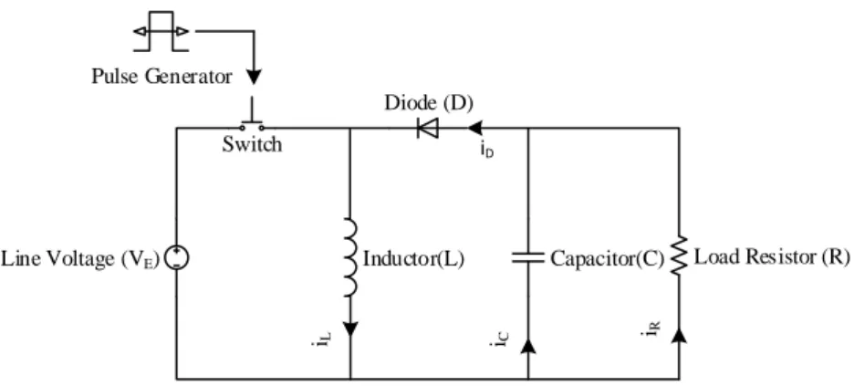
The Buck-Boost converter (combination of step-up and step-down) Figure 1.1 illustrates the elements arrangement for the DC-DC Buck-Boost converter. The DC-DC converter operates on a principle of pulse width modulation (PWM). A switch is added to control the flow of current from source to load, and a pulse generator controls the switch. During the switching period, the switch is open first and then closed until the end of the period (Lin, Wu, & Yang, 2013). A controller is used in a feedback loop to get liner output.
© This item
is protected
by original
copyright
3
Figure 1.1 DC-DC Open-loop Buck-Boost converter (Bryant & Kazimierezuk, 2002)
1.1.1 Output Stability Control
A system where the output does not affect the consequence of the input signal is called an open-loop system. On the other hand, the output of a system which depend at the feedback control signal, it is called a closed-loop system. The input signal will be changed accordingly based on the feedback from the output signal. A closed-loop is always better than an open-loop system because of controllability and reliability. A closed-loop control system is important for the safety of all electrical and processing systems (Dorf & Bishop, 2011).
The control system controller has numerous essential functions. They provide feedback to achieve the desired output. The automatic controller is used to control the variable at a specific level called the set-point. To achieve the constant output voltage across the load, a controller is added in a feedback loop which response on the feedback signal to maintain linearity at the output (Lin et al., 2013). Note that, It is not possible to get the desired linearity in the open-loop system. In a closed-loop system, these controllers have the ability to remove steady-state offsets through its integral action. Also,
Capacitor(C) Inductor(L)
Line Voltage (VE)
Switch
Diode (D)
iC iR
iL
Load Resistor (R) Pulse Generator
iD
© This item
is protected
by original
copyright
4
in the PID controller, it can anticipate the future through a derivative response (K.
Astrom, 1995; F. Luo & Hong, 2012).
1.2 Problem Statement
Gaining a linear output from the DC-DC Buck-Boost converter is difficult. It is complicated to design a feedback loop for the DC-DC Buck-Boost converter using the PID controller. Furthermore, it is a challenging task to tune the PID controller to achieve the output stability in a DC-DC Buck-Boost converter. This study seeks to resolve these issues.
1.3 Objectives
The research objectives are as follows:
1. To model the DC-DC Buck-Boost converter with PID controller using the state- space averaging technique.
2. To design a PID controller using modified Ziegler-Nichols method for a DC-DC Buck-Boost converter to improve its output voltage regulation.
3. To analyse the stability performance of the DC-DC Buck-Boost converter responses in steady-state under the line variation and load variation.
1.4 Project Scope
The primary target of the research is to develop a model of an open-loop Buck- Boost converter to understand the switching and response characteristics of the DC-DC converter. At the same time, a control law will be developed and verified using the state- space model. All simulations will be carried out in MATLAB. After that, a closed-loop
© This item
is protected
by original
copyright
5
feedback control system will be developed by using the PID controller. For PID control tuning, a modified Ziegler-Nichols Method will be adopted.
1.5 Organisation of Chapters
Chapter 1: Introduction
This chapter introduces the Buck-Boost converter operations and controlling method. The application of the converter is also mentioned. In addition, the project aims and objectives, problem statement and project scope are also stated.
Chapter 2: Literature Review
This chapter presents the background theory and the previous research in the same area. It focuses on the control of the Buck-Boost converter in order to get stable output using the PID controller.
Chapter 3: Methodology
This chapter details the implementation of controlling technique for the research as well as mathematical modelling and MATLAB simulation to obtain the desired results of the proposed problem.
Chapter 4: Results and discussions
This chapter analyse the stability performance of the DC-DC Buck-Boost converter responses in steady-state under the line variation and load variation which has obtained by simulation in MATLAB.
© This item
is protected
by original
copyright
6 Chapter 5: Conclusion
This chapter summarize the complete research information. It provides the analytical summary of research objectives, research methodology and some recommendations for future researchers.
© This item
is protected
by original
copyright
7
CHAPTER 2 : LITERATURE REVIEW
2.1 Introduction
A DC-DC converter is an electronics device that produces an output either, higher or lower than the input voltage (Lai, 2009b). Different converter topologies are used for this purpose. A Buck-Boost converter is the ideal topology due to its dual functions. It can be used to step-up and step-down the voltage, while the Buck converter can only step- down and the Boost converter can only step-up the voltage. The Buck-Boost converter is a combination of Buck and Boost converters (F. L. Luo & Ye, 2013).
The Buck-Boost converter cannot provide a smooth and stable output voltage because of the open-loop system (Sivasankar, Gayathri, & Vishnupriya, 2013). It is not possible to use it in various applications such as in telecommunication and solar electrical power generation, because of its output voltage stability. Nevertheless, researchers have found a solution by introducing a controller in a feedback loop to control the output voltage.
There are different types of controllers, but PID controller is more stable than others. The other most common types of controller are Proportional (P), Proportional Integral (PI) and Fuzzy Logic controller (FLC).
© This item
is protected
by original
copyright
8
The two types of the DC-DC converter are non-isolated and isolated. This study focuses on the non-isolated converter which includes:
Buck converter
Boost converter
Buck-Boost converter 2.2 Buck Converter
A Buck converter is used to step-down direct current voltage concerning the input voltage. Its main elements are diode, capacitor, inductor and switch. Figure 2.1 shows the circuit topology of Buck converter.
Figure 2.1 Buck converter
2.2.1 Working Principle
In most switched-mode power supplies, the transfer of energy level is controlled by a switch. During switching operations, the energy is stored in inductors and capacitors.
Capacitor(C) Line Voltage (VE)
Switch
iC iR
iD
Load Resistor (R) Pulse Generator
Inductor(L)
Diode (D)
© This item
is protected
by original
copyright
9
According to the desired time interval, the switch is turned ON and OFF using a pulse generator. The total period, T is denoted by:
ON OFF
T T T (2.1)
where TON is the time duration for its ON position and TOFF is the time duration for its OFF position. Meanwhile, a duty cycle, D is defined as:
T
DTON (2.2)
It is assumed that the output ripple is very small and the effect may be considered as constant during the conversion cycle. This negligible ripple in the cycle is called a small ripple approximation and by assuming it as constant helps to simplify the calculations.
2.2.1.1 During Closed Switch (ON)
As can be seen in Figure 2.1, when the current passes through the inductor it raises slowly as follows:
E O
L V V
di
dt L
(2.3)
© This item
is protected
by original
copyright
10
where VE is the source voltage and VO is the output voltage across the load.
While it is ON, the current increases by the amount:
( )
E O E O
L Closed ON
V V V V
i T DT
L L
(2.4)
2.2.1.2 During Opened Switch (OFF)
When the switch is opened, the inductor and ground link is blocked by the diode.
This diode is forward-biased in order to carry an inductor current while VL VO, where VL is the inductor voltage.
L
L O
V V Ldi
dt (2.5)
Then, the current starts decreasing in the inductor with a slope as according to:
0 O
L V
di
dt L
(2.6)
(1 )
O
L L V
i i
t D T L
(2.7)
( ) O (1 )
L Open
i V D T
L
(2.8)
© This item
is protected
by original
copyright
11
In steady-state, an average capacitor current is zero. Thus, an average inductor current must be the same as the average current (in the load).
O
L O
i i V
R (2.9)
The maximum inductor current is:
(max)
2
L
L L
i i i (2.10)
(max)
1 1 1
(1 )
2 2
o o
L o
V V D
i D T V
R L R Lf
(2.11)
f 1
T is the switching frequency, where f is the switching frequency The minimum inductor current is:
(min)
2
L
L L
i i i (2.12)
(min)
1 1 1
(1 )
2 2
O O
L O
V V D
i D T V
R L R Lf
(2.13)
© This item
is protected
by original
copyright