THE DESIGN OF THE DRIVE SYSTEM FOR A PERSONAL TRANSPORTER
by
Zainor Faisal bin Zainuddin
Dissertation submitted in partial fulfilment of the requirements for the
Bachelor of Engineering (Hons) (Mechanical Engineering)
MAY2011
Universiti Teknologi PETRONAS Bandar Seri Iskandar
31750 Tronoh
Perak Darul Ridzuan
Approved by,
CERTIFICATION OF APPROVAL
The Study of the Drive System for a Personal Transporter
by
Zainor Faisal bin Zainuddin
A project dissertation submitted to the Mechanical Engineering Programme
Universiti Teknologi PETRONAS in partial fulfilment of the requirement for the
BACHELOR OF ENGINEERING (Hons) (MECHANICAL ENGINEERING)
(Mr.
Azman Bin Zainuddin)
UNIVERSITI TEKNOLOGI PETRONAS TRONOH, PERAK
MAY2011
CERTIFICATION OF ORIGINALITY
This is to certify that I am responsible for the work submitted in this project, that the original work is my own except as specified in the references and acknowledgements, and that the original work contained herein have not been undertaken or done by unspecified sources or persons.
(Zainor Faisal bin Zainuddin)
ACKNOWLEDGEMENT
Alhamdulillah, praise to Allah I am able to complete the Final Year Project in time.
There are so many people who involve directly or indirectly during the construction of the project.
First of all, I am heartily thankful to my supervisor, Mr Azman Zainuddin, whose encouragement, guidance and support from the initial to the final level enabled me to develop an understanding of the subject.
I am highly indebted to most oflecturers in Mechanical Engineering Department for their guidance and constant supervision as well as for providing necessary information regarding the project
&also for their support in completing the project
It
is also an honor for me to have a family with their endless support throughout this project. I would not be able to finish the project without them.
Lastly, I offer my regards and blessings to all of those who supported me in any respect
during the completion of the project
ABSTRACT
Personal Transporters have been designed to help decrease the pollution emitted
and as a substitute to the typical combustion engine vehicle. However, due to its high
price and high maintenance cost, not many people can afford to have one. The aim of
the project is to design a low cost drive system. However, this report will have a more
detailed calculations and design process of the project. In the first phase of the project,
the author surveyed information related to the drive system of a personal transporter
nowadays. Most of the method used in the project is by analytical calculations since it
does not require building a prototype. The second phase of the project is mainly on
calculating the forces acted on the PT itself. It is to ensure that the drive power of the
designed PT can overcome the forces acting on it. A dynamic analysis was performed to
determine the power required to drive the PT at the specified mode of motion. The
transmission, battery and steering systems are also designed to meet the motion
requirement. The author will then select a design concept on how the PT will look and
where the drive system will be located. The design selected is based on suitability,
simplicity of the PT and comfort of the users. After that, the author select drive system
components with required specifications. Analysis on the components is needed to make
sure that the performance are the same if not better than the set specifications set in the
objectives. Towards the end phase of the project, the author may provide a detailed
design of the proposed personal transporter with some assumptions using CAD which
will help designer to actually fabricate the personal transporter. In conclusion, if the
project is a success, then it will help the designers to produce a low cost personal
transporter which indirectly help the consumers to own a personal transporter of their
own. With everyone having the personal transporter, it will help to ease congestion and
pollution problem in cities.
Contents
ABSTARCT ... ... !
CHAPTER!
INTRODUCTION
1.1 Project Background ... I 1.2 Problem Statement ... I
1.4 Project Scope ... . . ... 3
1.5 Significance of the project ... 3
CHAPTER2 LITERATURE REVIEW 2.1 Segway Human Transporters .... . ... 4
2.2 Modified Electric car ... 5
2.3 Personal Transporter Design by Syahril Izzat... ... 6
2.4 Other Types of Personal Transporter.. ... 7
2.5 Typical Architecture of Personal Transporter (PT) ... 9
2.6 Powertrain ... 10
CHAPTER3 METHODOLOGY 3.2 Brief Description on Methodology ... 14
3.3 Gantt Chart ... 15
CHAPTER4 DESIGN REQUIREMENT 4 .I Design Theory ... . . ... 17
4.2 Design Process ... . . ... 19
4.2.1.1 Rolling Resistance ... . ··· ... ··· ... 20
4. 2 .I. 2 Air Resistance . . . ... . . ... 21
4.2.1.3 Force required going uphill ... 21
4.2.1.4 Power required for Forward Motion ... 22
4.2.1.5 Power required for Acceleration ... 22
4.2.2 The Speed Control. ... 22 4.2.3 Gearing system Determination ... 23 4.3 Design Calculations ... 24 CHAPTERS
CONCLUSION & RECOMMENDATION
REFERENCES ... 39 APPENDIXES ... 41
List of Figures
Figure 2. 1 Segway Human Transporter ... 4
Figure 2. 2 Block Diagram for Modified Electric Car.. ... 5
Figure 2. 3 Design arrangement for S.Izzat PT ... 6
Figure 2. 4 Honda U3-X transporter and also how it fit into EV-N door ... 7
Figure 2. 5 Folded and non-folded Yikebike ... 8
Figure 2. 6 System architecture for Personal Electric Vehicles (6) ... 9
Figure 2. 7 Tractive effort of an IC engine and a multigear transmission vehicle versus speed ... 10
Figure 3. I Flow Chart of Methodology ... 13
Figure 3. 2 The flow of the progress for July' 10.... .. . . .. . . .. . . .. . . .. . . . . .. 15
Figure 3. 3 The flow of the progress for May'l1 ... 16
Figure 4. 1 Ackermann Theory Diagram<9l ... ... ... ... . ... 18
Figure 4. 2 Typical Performance Characteristics of Electric Motor for Traction ... 19
Figure 4. 3 Forces acting on vehicle moving uphill ... 20
Figure 4. 4 Resistive Motor Controller Schematic Diagram ... 23
Figure 4. 5 Electric motor selected for PT model MY1020 ... 26
Figure 4. 6 Spur gears arrangement for PT ... 28
Figure 4. 7 Battery and Charger for PT ... 30
Figure 4. 8 Steering mechanism ofPT using potentiometer ... 32
Figure 4. 9 Isometric view ofPTwithout chassis ... 33
Figure 4. !0 Free body diagram ofPT.... .. . . .. . . . . .. . . . ... 34
Figure 4. !1 Technical view ofPT (From left: front view, left view, rear view) ... 35
Figure 4. 12 Final product ofPT design using CA TIA ... 36
List of Tables
Table 1: Key specification oflzzat's Personal Transporter ... 7
Table 2: Key specification of the U3-X personal transporter ... 8
Table 3: Specifications for Motor Selected ... 26
Table 4: Specification for Gears Selected... . ... 29
Table 5: Specification for Battery Selected ... 30
Table 6: Cost analysis of the drive system components ... 32
CHAPTER!
INTRODUCTION 1.1 Project Background
People will keep asking "Why do we need a personal transporter when we have car and motorcycles which is convenient nowadays?" However, after so many years of using these transports, the clean and safe enviromnent we experienced before is getting to an end. Designers today are considering on inventing an alternative motorized transport which is safe towards the enviromnent as well as keeping the users comfortable. Therefore, the invention of personal transporter is an ideal set of idea toward realising the hope.
Although there are invention on electric bicycle in the early year, the modem types of transporter was introduced by Segway in 2001 is a new concept of personal transporter that gives more advanced and mobility with zero contribution to air pollution.
Personal transporter (Pn or personal electric vehicle (PEV) can be define as vehicles which transport a single passenger over trip distances of 1-10 km and employ electricity as the motive energy source. (I) It consists of electric motor, controller, batteries and chassis. Even though it is speculated as future vehicles, most people today still consider it unnecessary.
The drive system and the steering system are considered as the most important component of the personal transporter. For the convenient of the users, designer will have to create a user friendly drive and low cost system to make it affordable to everyone.
1.2 Problem Statement
The design of the personal transporter has been inspired to overcome the problems of the combustion engine vehicles which are:-
I. High pollutant content released.
Since the personal transporter does not use its own internal combustion engine as the power source, there will be no exhaust and therefore zero emission. The smog from car engine is one of the reasons for "Green House Effect". (1)
II. Less reliability
Compared to the conventional vehicles, personal transporter has less moving parts. An electric motor for example has only one moving part which is the rotating shaft However, the typical combustion engine has more than 100 moving parts that are designed to work together for them to function properly. This will increase the possibility of engine fuilure rather than the electric motor. (1)
III. Too dependent on non-renewable energy sources.
This is one of the main points that electric powered motor is better than conventional automobiles. Depletion of the resources results in the increasing of crude oil prices. A car using an electric power is less dependent from the fluctuating of the global crude oil prices. (2)
These disadvantages of combustion engine have been overcome by producing the PT. However, the existing PT also have disadvantage which contribute to the lack of consumers usage of the PT that is:-
IV. Existing Personal Transporter are too expensive
Today, there are companies that came up with solutions to overcome the short distance, environment friendly vehicles. However, the price of the existing PT not competitive compared to conventional vehicles. An alternative cost saving PT needs to be design so that it can satisfies the group of consumers.
V. High technology tool used which complicates personal maintenance.
The existing PT like Segway used complex system. Therefore, it is impossible for consumers to actually maintain the PT without having professional supervision. The equipments used are also considered expensive and not accessible in the market.
1.3 Objectives of the Project and Scope of Study
The objective of the project is to simplify the design of drive system of the existing personal transporter. The simplified drive system will be consisting only the main parts which are the motor, controller, battery and gearing system.
There are several design factors that have to be taken into account such as the weight, speeds and the distance that the PT can travel to ensure users experience a comfortable ride as while making it affordable to public.
1.4 Project Scope
The PT performance will be based on the specifications set by S.lzzat (2009):
• Total Mass (Transporter +Rider)= llOkg (30kg+80kg)
•
•
•
•
V max = 20 kmlhrs
Distance travel per full charge = I 0 km Charging Time = 4 Hrs
Maximum slope angle of ascent= 25°
However, these requirements may be changed in order to increase the performance of the transporter. The output of the project will be in the form of detail design using CA TIA drawing.
1.5 Significance of the project
Due to the completion of the project, users will be able to experience a zero gas emission vehicle with less money spent. High pollutant content in air will significantly be reduced and promote a clean and healthier environment.
The usage of a personal transporter will also be a perfect alternative to avoid traffic jams on freeways. It will also be a better economy solution since we will not only depend on non retrievable energy source.
The analysis of the drive system may also provide useful information to the designer of the PT.
CHAPTER2
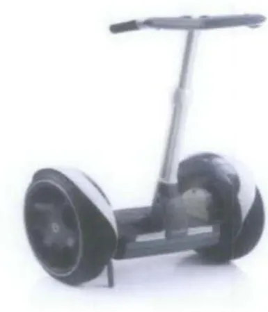
LITERATURE REVIEW 2.1 Segway Human Transporters
The machine was described as the first self balancing human transporter. Its ability to stand on its own with only two wheels side by side is remarkable. Segway HT uses a lean steering system which enable rider to drive the vehicle forward or reverse by leaning on the handlebar. <4>
At its most basics, Segway consist of a series of sensors, a control system and a motor system. The primary sensor system of Segway is the series of five gyroscopes. These gyroscopes are the spinning wheels inside the HT to resist changes because an applied force moves along with the object. Segway uses the solid state angular rate sensor constructed using silicon which determines the objects' rotation using Corio! is effects.
Figure 2. I Segway Human Transporter
In addition, Segway has two tilting sensors that sense its own position relative to the ground. The tilting of the device is processed by two electronics controller circuit boards. They check the position sensors I 00 times per second and run advance software that monitor the stability information and adjusting the speed of the vehicle.
Each wheel is driven by a 2 HP motor independently. One motor will operate faster than the other if the rider decides to move to the right or left. The Segway operate a two stage transmission with gear ratio of 24: l.Helical gears are used to reduce noise. Design of a non integer gear ratio is chosen so that gear teeth mesh at different point and gearbox life will be extended. <4>
The motor can received power from either Nickel Metal Hybride (NlMH) or Lithium lon batteries. Both batteries are rechargeable and can be easily charge with the AC household current. However, the Segway did not have a braking system. It will be stopped when the rider is in upright position without the rider leaning the handle bar forward or backward (4)
2.2 Modified Electric car
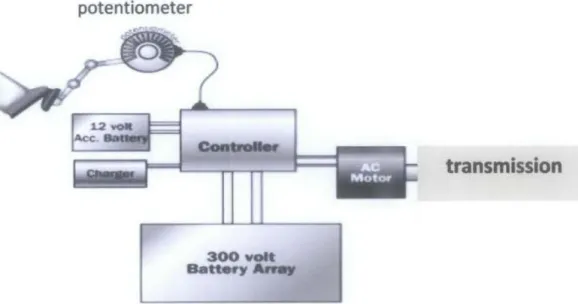
A normal engine is modified to turn into an electric car. First of all, an electric 3-phase AC motor is bolted into the transmission with an adapter plate. An AC electric controUer is added to control the AC motor. The controller takes power from the batteries and delivers it to the motor. There are potentiometers that will be attached to the acceleration pedal that controls the power that need to be delivered.
potentiometer
transmission
Figure 2. 2 Block Diagram for Modified Electric Car
In order to power the motor for the electric car, 50 units of 12V of batteries are needed to power up to 300V to the controller. The controller will convert the DC
current to a 240V AC to the motor. It uses rechargeable lead acid batteries for the power source. The controller also does the pulsing for the rider so that it will conduct a constant voltage to the motor without stepping on and off tbe pedal. Without the controller, tbe pedal will acts as a switch unit that will tum on and off to maintain current delivered to the motor. Vacuum pump is used for the power brake.
The electric car is capable to obtain the range of 80km on a single charge.
However, the weight of batteries may be a problem for tbe vehicle which can exceed 500kg. (S)
2.3 Personal Transporter Design by Syahril Izzat
The Personal Transporter proposed by Syahril Izzat is mainly to reduce tbe cost of the transporter so that it is affordable to most consumers. The transporter was not design for an easy mobility of the vehicle since the total weight of the PT is approximately 95kg. The usage of three batteries consumed the most space and contributes to the total weight of the vehicle.
Battery
Figure 2. 3 Design arrangement for S.lzzat PT
The PT uses a Forward Wheel Drive with two wheels at the back of tbe PT and it runs on a single lOOW motor that situated at the back. With only one gearbox used, the total cost of the PT is reduced to an affordable price. The speed of tbe vehicle is 20km/h. <3l
Table I: Key specification oflzzat's Personal Transporter Total Weight (Rider+Pl) 165kg
Motor IOOOW
Batteries 12V and I 8Amh
Speed ofPT 20kmlh
Time Travel Apprx. 30 minutes
Distance Travel IOkm
2.4 Other Types of Personal Transporter
2.4.1 Honda U3-X personal transport device
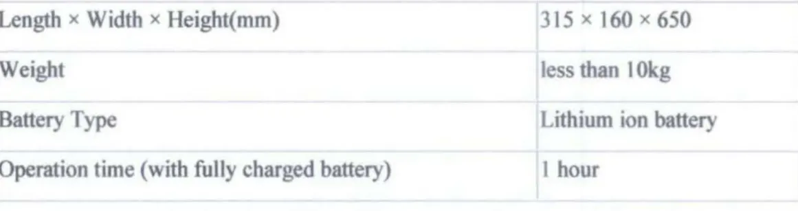
Honda U3-X is aPT without handle bar produced by Honda. Weighing just less than 1 Okg, 650mm tall, 30cm long and 15cm wide- this self-righting unicycle is so small that it can fit into the car door of Honda's new concept electric car the EV-N.
I
-
Figure 2. 4 Honda U3-X transporter and also how 11 fit into EV-N door
The U3-X boasts about an hour of battery life and it has top speed of just under I Okmp/h. The key concepts behind the design are simply to make a personal transport device that is easily stored, non-obtrusive if taken on larger public transportation like trains or buses, eas} to operate and fun. Table below shows key specification ofthe model.
Table 2: Key specification of the U3-X personal transporter Length x Width x Height(mm)
Weight Battery Type
Operation time (with fully charged battery)
315 X 160 X 650 less than I Okg Lithium ion battery 1 hour
Honda developed the world's first wheel structure which enables movement in all directions including forward, backward, side-to-side and diagonally. Multiple small- diameter motor-controlled wheels were connected in-line to fonn one large-diameter wheel. By moving the large-diameter wheel, the device moves forward and backward, and by moving small-diameter wheels, the device moves side-to-side. By combining these movements the device moves diagonally.
2.4.2 Yikebike
The 'Yikebike' by inventor Grant Ryan and engineer Peter Higgins of New Zealand, is a mini-farthing bike designed to battle the increasing urban congestion oftoday. It uses carbon fiber frame and weighs less than I Okg. Yikebike's electronic can travel at speeds up to 20 kmlh and having range of 1 0 km.
Figure 2. 5 Folded and non-folded Yikebike
The transporter cost around 5,500 USD. It uses Electric brushless DC motor which generates 1 kW of power.
Built from carbon fiber and weighing in at I Okg, the Yike Bike is powered by a custom lkW motor, a better power to weight ratio than many sports cars, and can be fully recharged in under 30 minutes. Weight limit for the usage is about I 00 kg. In terms of form factor, the Yike Bike operates using an electric chain less drive on its front 20' hub less wheel.
2.5 Typical Architecture of Personal Transporter (PT)
The PEV is comprised of the basic function of energy storage, drive system and chassis. The drive system is consisting of one or more motors which transmit power and torque to the wheels through a mechanical transmission.
Charging
-1
Controller Motor(s)I
Energy Storage
I
I
Transmission Drive SystemI
I
Rider InterfaceII
BrakingI
I I
Wheels Structure
Chassis
Figure 2. 6 System architecture for Personal Electric Vehicles (6)
The central technology choice for the drive system is between a brushed DC motor and a brushless DC motor. The difference between these technologies lies in the way the motor is commutated. Commutation is the switching of electric power to the appropriate coil in the motor winding at the appropriate angle of revolution of the motor rotor. For brushless motors, the windings are most commonly in the stator and permanent magnets are in the rotor. This arrangement provides better cooling, and therefore higher power levels for a given mass of copper and steel.
Motor torque is proportional to motor current. For brushed motors, high levels of current result in substantial inefficiencies due to resistive losses in the brushes. For this reason and because of cooling limitations, brushed motors are most efficient when run at relatively high speeds (5000-20,000 rpm) and low torques. In contrast, brushless motors can operate efficiently at high torques and speeds as low as 1000 rpm. This difference in minimum efficient speed leads to a substantial difference in transmission requirements. Given their inherent ability to operate efficiently at lower speeds, brushless motors can often be configured with a single-stage transmission such as a single pair of spur gears, pulleys, or sprockets, whereas brushed motors are typically best matched to a two or three-stage gear drive with sufficient gear reduction to match the motor speed to the speed of the drive wheel(s ). (6)
2.6 Powertrain
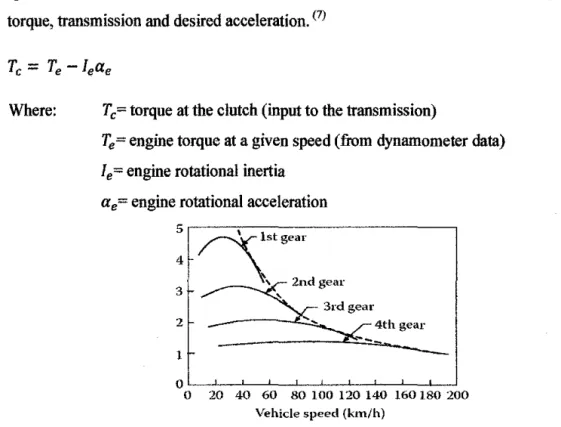
Focusing on the target of engines revolution per minute that is low rpm at higher speed, there comes a need on the study of the relation between tractive forces, engine torque, transmission and desired acceleration. (?)
Where: Tc~ torque at the clutch (input to the transmission)
Te
=
engine torque at a given speed (from dynamometer data) 1 e = engine rotational inertiaa.~ engine rotational acceleration
5,----.~---.
4
~lstgear
3
__..--\~,
2nd gear2 4th gear
1
0oL_~2~0~40~~60~~8~0~1~0~0~1~20~1~40~1~60~18L0~20-0
Vehicle speed (km/h)
Figure 2. 7 Tractive effort of an IC engine and a multigear transmission vehicle versus speed The output torque can be approximated by the expression that involved the gear ratio of the transmission: (7)
Where T d= torque output to the drive shaft
It= rotational inertia of transmission (as seen from engine side) N1
=
numerical ratio of the transmissionThe last stage is where the torque delivered to the axles to accelerate the rotating wheels and provide tractive force at the ground is amplified by the final drive ratio with some reduction from the inertia of the driveline components between transmission and fmal drive. (7)
Where Ta = torque on the axles Fx=tractive force atthe ground
r= radius of the wheel
lw= rotational inertia of the wheels and axles shafts aw= rotational acceleration of the wheels
I d= rotational inertia of drives haft ad= rotational acceleration of driveshaft N1
=
numerical ratio of the final driveThese co-related expressions in transmitting the power from the engine to the wheels can be combined into:
Where Nt1
=
combined ratio of transmission and final drive Tltr= combined efficiency of transmission and final driveKnowing the tractive force, we can now predict the acceleration performance of a vehicle. We had to add up a few more external forces such as the expression:
Where
Also
Rx= rolling resistance forces D A= aerodynamic drag force Rhx= hitch (towing force) (I)= inclination angle of road
and
After we the wheel rotational speed, Ww we can find the translational velocity of the vehicle.
Reviewing back to term of Nq that is the combined ratio of the transmission and fmal drive, which is what the objective is about. To calculate which is the best gear ratio combination for our purpose of low operating rpm since we are desired in making a variable transmission gearing system. C7
l By this equation
Max= .!::ax
=
Fx- Rx- DA- Rhx- W sin (I) gAnd neglecting the inertia losses f. _ TeNttqtf
x - r
We can predict the suitable gear ratio after we decide on the value of desired engine torquer., forward vehicle's accelerationax, and inclined angle of the road 0. C7l
CHAPTER3
METHODOLOGY
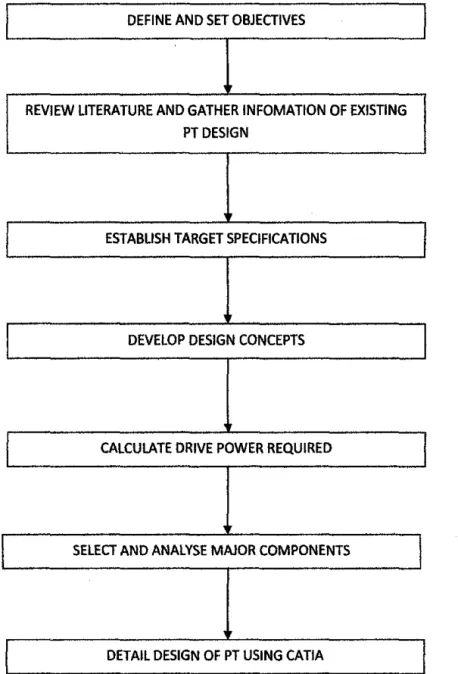
3.1 Flow ChartThis chapter will describe the methodology employed to implement this project.
DEFINE AND SET OBJECTIVES
REVIEW LITERATURE AND GATHER INFOMATION OF EXISTING PT DESIGN
ESTABLISH TARGET SPECIFICATIONS
DEVELOP DESIGN CONCEPTS
CALCULATE DRIVE POWER REQUIRED
SELECT AND ANALYSE MAJOR COMPONENTS
DETAIL DESIGN OF PT USING CATIA
Figure 3. 1 Flow Chart ofMethodology
3.2 Brief Description on Methodology
The basic flow of the project is shown in Figure 3.1. The process involve in studying the drive system of a personal transporter consist of several steps. In order to achieve the targeted performance, describing part by part of a drive system is crucial. The methods cover from selecting a personal transporter until achieving the desired performance.
The frrst step in designing a process is to study the parts which relate to the drive system of a PT. Study will be done with different kind of transporters which have variable types of drive systems. The scope of the drive system consists of the motor, the batteries and the gearing system.
The different types of transporter will be analysed to list out the advantages and disadvantages of the drive system. Detail study on the selected PT will be carried out to compare with each other. The best drive system which has the lowest cost while maintaining a standard performance will be chosen.
The requirements for the drive system are chosen to suit the consumers' choice. The requirement will be based on the objectives of the project that is to produce a low cost and simple drive system for them.
Multiple design concepts will be developed in order to know how the PT is going to run and sample of the initial design of the PT will be produced.
Advance study in the recent design will then be extended to improve the performance ofthe personal transporter. The selection of the drive system parts are made after further study on them. The design of the transporter will be shown using CA TIA software. CA TIA software is chosen instead of AutoCAD because extra parameter such as the density of the frame can be added.
Lastly, the final design of the personal transporter will be proposed together with the list of materials chosen.
3.3 Gantt Chart
Selection of Project Topic Research and Analyse Problems
Scope of Drive System
and Selection ofPT as Main Revision
Requirement
Concept to Achieve Requirements
Figure 3. 2 The flow of the progress for July' I 0
Detail/Week
components used Analyse Suitability of each components Evaluate
design
Detail Design of the PT using CA TIA
I 2 3 4 5
6 7 8 9
I 0 II 12 13Figure 3. 3 The flow of the progress for May' II
CHAPTER4 DESIGN REQUIREMENT 4.1 Design Theory
The specifications of the transporter are based on the study done on articles and journals. There are proves that specifications that had been set are considered safe to run on the pedestrian walk. (SJ
Speed - 20km/h
This is a standard running speed of a human being. The highest speed that considered safe on pedestrian walk is less than 30kmlh which is the speed of people riding bicycle. The maximum speed also allows easy manoeuvrability and breaking.
(8)
Travel Distance -lOkm
The PT is a short distance vehicle. The specification that had been set is considered sufficient enough for consumers to travel safely throughout the city.
Maximum Weigbt-30kg
Consumers will be expecting a light weight PT which will provide them mobility to catty the vehicle wherever they want. f8l
Slope to overcome- 20°
The target of the designed Personal Transporter is on the economical aspect of PT rather than the performance. However, the performance of the PT will be design to compete the performance by Segway. <8l
4.1.1 Drive System and Steering System
The proposed design is a three wheeled personal transporter with two front wheels.
The transporter will be driven by a motor which will be connected to the rear wheel.
The method chosen is due to the simplicity of the design proposed by former student.
The front wheels are the steering wheels for the transporter and is design using the Ackermann theory. It is design to solve the problem of wheels on the inside and outside of tum needing to trace out circle of different radii.
,. J:·'.''"'
0!-:.~~--~---
Cenn-e of ttnning r.:il:cle-
t · · · ._Figure 4. I Ackermann Theory Diagram<9>
The first aspect of a design for personal transporter is the drive system of means power transmission. Motor will transmit power to the rear wheel. The motor control will be decided for motor speed and braking. They will be incorporated using a simple joystick to facilitate operation by the user. The diagram for the description of processes involve is shown on Appendix 2.
The difficulty faced for this type of drive system is to get the required speed reduction when the high speed motor is providing power. The problem can be solved by using a gear motor but since the objective of the project is to reduce cost, simple single gear transmission will be conducted in the project. <•> ·
4.2 Design Process.
4.2.1 Motor Power Determination:
Some calculations are needed to determine how much power required by the motor in order to drive the PT at the desire specification.
Electric motor usually has a mostly ideal speed-torque characteristic. From figure below, as the motor speed increases to the base speed, voltage increases to the rated value while flux remains constant. Beyond that, the voltage remains constant while flux is weakening. This result in constant output power while torque decline hyperbolically. 1121
80 70
80
~50
140 130
20 10
00~--~~~~~~~--~~--~
Figure 4. 2 Typical Performance Characteristics of Electric Motor for Traction The movement behavior of a vehicle along its moving direction is completely determined by all the forces acting on it in this direction.
There are three major forces at work which resist a vehicle from moving:
I. Rolling resistance 2. Air resistance
3. The force of gravity as a vehicle moves up a hill
Figure 4. 3 Forces acting on vehicle moving uphill
The tractive effort, F1, in the contact area between the tires of the driven wheels and the road surface propels the vehicle forward. The total force that needs to overcome is:
FTraction =FAir+ FRoll + Fslope
4.2.1.1 RoBing Resistnnce
The force of the rolling resistance is a function of the weight of the vehicle multiplied by a coefficient of the rolling resistance. [121
This force is mostly independent of car speed.
Froll
=
Uroll M llgrnvity (eq 4.2.1)Where:
Uroll -is the rolling resistance coefficient. Typical values for the rolling resistance coefficient (uron)
=
0.0136 + 0.04 • 1o·
6*
(v*
3.6)2, where vis the function of speedM -is the mass of the vehicle (kg)
agravity-is the force of gravity (9.8 m/s2)
4.2.1.2 Air Resistance
The force of the air resistance is proportional to the square of the speed, the density of the air, the silhouette area of the car, and the drag coefficient for the vehicle. (IO) A vehicle travelling at a particular speed in air encounters a force resisting its motio""
referred to as aerodynamic drag resulting from two components: shape drag and skin friction.
(eq 4.2.2)
Where:
Cd- is the Drag coefficient (no dimension) A- is the surface area of the car and rider (m2)
p- is the density of the air (1.2 kglm3 at sea level at normal temperatures) v-is the speed of the vehicle (m/s)
PT area: APTr
=
0.2 m2Human body area: BSA =
v'
(h*
m /3600) =;I (180cm*
80kg /3600) = 4 Where: h = 180cm and m = 80kg1FSA = 2/5 BSA = = 2/5 (4) = 1.60 m2
Total air resistance area: A= 1.60 + 0.2 = 1.80 m2
With; Air density: p = 1.225 kg!m3 Drag Coefficient, Co= 1.5
4.2.1.3 Force required going uphill
The force required to lift a car uphill is a function of the angle of the hill and the force of gravity. [!ZJ When a vehicle goes up or down a slope, its weight produces a component that is always directed in the downward direction.
Fslope =sin(% grade of slope) M !lgrnvity
Where:
M- is the mass of the vehicle (kg) is the force of gravity (9.8 m/s2)
(eq 4.2.3)
4.2.1.4 Power required for Forward Motion
Power is a measurement of work per unit time. Work is a measurement of a force moved some distance. Therefore to determine the power required moving a vehicle at a certain speed, it is simply the total of all forces to overcome multiplied by the speed. (IOJ
P = (Fron +Fair+ Fhm) V
4.2.1.5 Power required for Acceleration
The PT is set to accelerate at the rate of lm/s2• To calculate the power required to accelerate a vehicle, first determine the amount of energy required to accelerate a vehicle from 0 to a speed v:-
Where:
M- is the mass of the vehicle (kg) v-is the final speed of the vehicle
Then to calculate the power, divide the energy required by the time it takes to accelerate the vehicle:
Where:
Ek-is the energy required to accelerate the vehicle to the speed t- is the time is takes to accelerate the vehicle to the speed 4.2.2 Tbe Speed Control.
Motor controller is required to turn the control signal from the microcontroller into a varying power level to drive the motor. The PT will have a Pulse Width Modulation (PWM) controller as tbe speed controlling device. PMW is one method to communicate between micro controllers to a motor controller.
Another type of speed controlling device that can be used is Resistive motor control.
It consisted of two switches. One switch operated the motor at a slow speed, running current through a power resistor, and the second resistor shorted out the resistor, giving full speed. Knowing the voltage and current we wanted to limit in slow speed, a value for resistance was calculated using Ohms law. (11)
Higft/low Spe•d Switch
Resisto.-
Motor
Figure 4. 4 Resistive Motor Controller Schematic Diagram Ohms Law states V = ffi, therefore,
R =VII, where:-
V = Voltage, I = Current, R = Resistance
The only advantage that Resistive controller has against PWM is that it may potentially more reliable. The PWM offers better performance in speed control and have improve efficiency of vehicle. (11)
4.2.3 Gearing system Determination.
Since the speed-torque motor is close to ideal, single gear or double gear transmission is usually employed. <10lfor this project, a single gear transmission will be employed.
The basic equations used here are:
P
=
(1/60)*Il*N *TWhere,
P- Power in KW N- Speed in Rpm T- Torque in N.m
M- Number of teeth of the respective gear.
4.3 Design Calculations.
4.3.1 Total forces encountered
From equation ( 4.2.1 ), Froll = UroJl M llgravily
= (0.01862)(110 kg)(9.81 m/s2)
=20.02N From equation ( 4.2.2) Fair
=
Y, Cd A p v2= Y, (1.5)(1.8 m2)(1.225 kgim3)(5.56 m/s2
i
=51.!2N From equation ( 4.2.3)
F slope = sin (% grade of slope) M llgravily
=sin 25(11 0 kg)(9.81 m/s2)
=456.07N
The total traction forces that PT will encounter are:- FRoll = 20.02 N, Fnrag = 51.12 N and Fstope = 456.07 N Ftrnction = FRoll + Fnrag + Fstope = 527.18 N
The highest possible forces will be taken into the calculation in order to get the maximum traction forces that the PT will faced.
4.3.2 Torque required at wheel Using Tw= Fr
Tw=Torque
F1= Total Traction Forces r = Radius of the Driven Wheel
Therefore, the torque at wheel is 105.44 Nm. The torque that has been calculated is the smallest torque that the wheel needs in order to move the PT. Any value less than the torque will not move the PT.
4.3.3 Rotational Speed and Torque at Wheel
Since the torque has been calculated, the rotational speed of the wheel is needed in order to move the PT to the required speed that is 5.56m/s translational.
Using:-
v=wr, where:-
V- Translational Speed ofPT W- Rotational Speed ofPT R- Radius of wheel (0.2m)
The required rotational speed required is calculated to be 27.8 rad!s to achieve translational speed of 5.56m/s.
4.3.4 Gearing System
Figure 4. 5 Electric motor selected for PT model MY I 020
For the project, a 24V SOOW DC Electric Motor has been chosen to run the PT. The specifications of the motor are shown below:-
Table 3: Specifications for Motor Selected 112)
Model MYI020
Type Brush
Voltage 24VDC
Rated Speed 2500RPM
Rated Current 27.4Amp
Sprocket 8mm, 13 tooth pinion gear
Output Power
soow
Dimension(Length X Weight X Height) l74.00mm X 72.00mm X 184.00mm
The required torque for the PT is II 0.32Nm at the wheel. Calculations to find free torque of the motor are shown below:-
500 W
=
0.67 HP HP=
T *N/63025 p (t2lTherefore,
Tp = 0.67HP*63025/2500 rpm
= 16.89Nm Where:-
T=Free Torque of motor (ft.lbs) N=Rotational Speed (RPM)
From equation above, the free torque of the motor is 16.89 Nm and needed to be increased by using gear ratio. However, the rotational speed required will also be considered during the calculation. The lowest rotational speed produced using gear ratio is 27.7 radls.
Therefore, to get a total torque at least 110.32 Nm:- Gear Ratio,
io
= 105.43 Nrni16.89Nm=6.25
However, the gear system of the PT will not have a perfect efficiency of 100%. The author assumes that the gear system has 98% efficiency. Therefore, using the formula:-
= 105.43 Nm/(0.98)(16.89 Nm)
=6.46
With all the consideration taken, the gear ratio of at least 6.5 needed to be used.
4.3.4 Performance ofPT
In order to get the required standard, the gear ratio of 7 will be used. The performance of the PT is calculated to be:-
Torque on the Wheel= 16.89 Nm*7
=
118.23Nm Rotational Speed = 261.8 rad/s/7 At Wheel = 37.4 rad/sThe PT will have translational speed of 7.48 m/s or 26.9 kmlh. This speed is considered safe since the required speed set is at least 20 kmlh and more than 3 Okmlh is considered dangerous too drive on pedestrian walk.
Isometric view Scale: 1:1
Figure 4. 6 Spur gears arrangement for PT
Table 4: Specification for Gears Selected
Pammeter Gear A GearB GearC GearD
Diametral pitch, P 6.000 6.000 6.000 6.000
Number of teeth, N 13.000 28.000 17.000 55.000
Base Diameter, d (mm) 61.000 132.000 80.000 260.000
Module,m 5.000 5.000 5.000 5.000
Circular pitch, p 0.628 0.628 0.628 0.628
Pressure angle 20° 20° 20" 20"
Dedendum, b 0.225 0.225 0.225 0.225
Material: Ductile Iron Grade 60, Density; 7.10g/cm'
Train Value TV= VR a.bx VR b-o
Train Value TV= 28113 X 55/17
= 6.97 (which is approximate to 7) 4.3.5 Battery performance
Before selection of battery being made, the time needed for the PT to travel at least lOkm with the speed of26.9km/b is calculated:-
Time to travel = lOkm I (26.9km/h)
= 0.371 hour (22.3 minutes)
The motor is drawing a steady 27.4 A of current and the PT needs the motor to run for at least 0.371 hour. Thus:-
Capacity battery needed= 27.4 A* 0.371 hour
= 10.1654 Ah
However, in real life, it is impossible to run the battery all the way on every charge cycle to zero. The battery should have at least 20% left of the total capacity.
Therefore:-
Capacity Battery
=
I 0.1654 Ah I 0.8 ::: 12.71 AhTo power the motor, a 24V l3Ah NimH battery pack is selected. This type of battery is widely used for Hi-Power E-bike and robots. It consist of 20 pieces of F sized 13Ah NimH CeJI in a plastic container. The battery needs to be charged using the Smart Charger (1.8A) with 3 pin connector which is installed to the home plug.
(12)
Figure 4. 7 Battery and Charger for PT
Table 5: Specification for Battery Selected 112>
Nominal Voltage 24V
Nominal Capacity 13Ah
Standard Discharge Time 13A
Charging Time 160min
Weight 5.4kg
Dimension(Leogtb X Weight X Height) 76.22mm X 168.3mm X 18l.Omm
The perfonnance of the battery will be based on the assumption that the vehicle is operated at an elevated surfuce where the inclination is 0°.
Therefore, the battery will last for T where:- T
=
13Ah/27.4A=
0.474h=
28min 28secThe vehicle will operate at a speed of 26.9kmlh. So, the total distance that the vehicle may cover is D, where:-
D
=
26.9km!h*0.474h=
12.75kmSince the objective of the project is to get a total distance of at least I Okm, therefore the objective is achieved.
4.4 Steering Mechanism
Steering mechanism plays an important part in providing comfortable way to control the direction and accelerating the PT. Many considerations had been made during the designing progress. Two of the rejected ideas were wheel mounted in the upright post in front of the PT and a simple knob on the post itself. It was decided that twist grip would be the most appropriate for the project. It seems simple for user to use as well as the designing process.
The basic idea of accelerating the PT is using a potentiometer in the twist grip handlebar to control the current going through the electric motor. Therefore, the speed of the motor can be controlled by manipulating the resistance on the potentiometer.
Figure 4. 8 Steering mechanism of PT using potentiometer
4.5 Cost Analysis
This section provides a summary of the cost associated with the PT. The table below shows the list cost of major comJX>nent in the drive system.
Table 6: Cost analysis of the drive system components
ITEM COST
DC Motor RM450
Batteries and charger RM 195
Controller RM 150
TOTAL RM795
•These pncing are based on the current reseach on the website www.monsterscooter pats.com.
The total price ofRM 750 is only based on the drive system ofthe PT. However, the cost is 3.75% of the total price ofSegway Human Transporter which cost about RM 20,000 in Malaysia.
4.6 PT Detail Design
Isometric v:i.ew
sca~e: 1 : 1
Figure 4. 9 Isometric view ofPT without chassis
The figure above shows the output product of the PT design by the author. It runs on a single motor Rear Wheel Drive which simplifies the design of the PT. Since it only runs one wheel, there is no need a drive shaft to be installed. The two front wheels are steered by turning the handlebar to left or right. The steering system is accomplished by the Ackermarm Theory.
The drive system of the PT is assembled at the back of the PT to balance out the PT with the user at the front. Therefore, the center of gravity of the PT will be located at the center and the PT will not be flip over. The lower the center of gravity, the balance the PT. The calculation to find the center of gravity of the PT is shown below:-
Battery
Motor
9.2cm
Wheel
Rider
Center of Gravity
~-..:~~-
• •
I ' • •
I '
•
• •
-.
20cm
40cm
65cm
• •
..
~:22.1cm Figure4. 10 Free body diagram ofPT
Human (Height 180cm, weight 80kg) Battery (Weight 6.0kg)
Electric Motor (5.0kg)
To obtain center of gravity acting the composite body;
X="ExW/"EW Y="EyW/"EW
73.8cm
9.5cm
---t
________ t __ _
y
Mass = 135 kg Weight= 891.7 N
90cm
X= [(65x6.0) + (40x5.0) + (80x20)]/ (6.0+5.0+80)
=22.12 em
Y = [(9.2x6.0) + (9.5x5.0) + (90.0x80)]/ (6.0+5.0+80.0)
=73.8cm
From Figure 4.1 0, the red dot shows where the center of gravity of the PT with the rider on it. Since the location of the center of gravity is not at the end of the PT, it can be considered balance and will not flip.
Figure 4. I I Technical view ofPT (From left: front view, left view, rear view)
The dimension of the PT is shown on the Figure 4.11. The size of the PT is considered fit enough for a single person transporter. The center of gravity of the transporter which located at nearly the center of the transporter proved that the PT is highly balance and will not flip over at static or moving state.
The final product of the proposed Personal Transporter is illustrated using CA TIA software.
Figure 4. 12 Final product of PT design using CA TIA
CHAPTERS
CONCLUSION & RECOMMENDATION 5.1 Conclusion
After all the research and analysis done, the author is able to decide on a three wheel rear drive PT. A 24V DC motor with 500W power enables it to achieve a speed of 26.9km/h and a total distance of 12.75km. The power source of the PT is a 24V 13Ah NimH battery pack that can run about 28 minutes with a single charge. With a gear ratio of 7 and maximum torque of 118.23 Nm at the wheel, the PT would be a perfect choice for a single rider with less than 80 kg body weight to ride on a flat surface up till 20° inclination plane. The author hope simplify version of the PT is more user friendly and enables users to maintain it easily.
By cutting down the usage of sophisticated components on the PT, it is hoped that the cost of the PT can overcome the problem of high prices in the existing PT. The design of the simplified PT cost no more than RM 1000 which only 3.75% of the cost ofSegway. Thus, more users will be aware of the sickening environment.
Last but not least, the author also hopes that this report is able to become a reference in helping the designers to fabricate the personal transporter in the future.
5.2 Recommendation I. Produce a prototype.
Analytical analysis would not provide an exact result compared to a prototype.
Therefore, a real experiment of the PT needed to be done in order to get the best result outcome. By doing this, the uncertainties that might be encountered can be detected and solved. The motor, battery and gear train wilJ not have I 00% efficiency and thus require performing the experiment to determine the exact efficiency of the components.
2. Material Selection
The types of material used for the PT wilJ have a significance effect on the PT. The lighter the weight of the material, the higher the efficiency of the drive system. Since the author only covers the drive system design, all of the material selections and weight are considered negligible. Therefore, the analytical analysis wilJ not have an exact result ofthe performance of the PT.
3. Detail study on maintainability ofPT
The quality of a product lies on the maintainability of the product itself. With a detail study on this, components that wilJ need retaining to a specified condition within a specified period can be known. Therefore, a lifespan of the product can be expanded due to the continuous improvement and maintenance.
4. Mass production
Another objective of the project is to reduce the total cost of the PT. However, if a product is produce in a limited amount, the price of the product will be higher. Thus, a mass production of the PT will eventually decrease the total cost of the PT with an accurate manufacturing procedure.
REFERENCES
1. Morchin, William C. Electric Bicycle :A guide to design and use. s.l. :John Wiley and Sons Ltd, 2006.
2. Sharp, Archibald. Bicycle and Tricycle A classic trearies on their design and construction.
s.l. : Longmans, 2003.
3.1zzat, Syahril. Drive Mechanism for Personal Transporter. s.l.: Universiti Teknologi PETRONAS, 2010.
4. Usborne, David. What Happened to the Segway. News UK. [Online]19 5, 2007.
http://www.independent.co.uk/news/uk/this-britain/whatever-happened-to-the-segway- 449502.html.
5. Coonstructing an Electric Car. [Online]2008. www.electric7.com/construction.html.
6. Ulrich, Karl T. Estimating the technology frontier for personal transporter .. s.l. :Research C Future Personal Transporter, 2006.
7. Jefferson, C. M. Hybrid Vehicle Propulsion, WIT Press. 2002.
8. Screengrafity. SEGWAY. Science ofSegway. [Online]22 February, 2010.
http:l/robbie.dmlive.co.nz/summatives/02/science.html.
9. Donald Bastow, Geoffrey Howard, John P. Whitehead. Car Suspension and Handling.
Fourth Edition.
10. Iqbal Hussain, Vehicle Fundamentals., CRC Press LLC, 2005.
11. Speed Controllers. [Online]510, 2005.
http://homepages.which.net{-paul.hills/SpeedControllersBody.html.
12. Motor Selection. Electric too/ box. [Online]2010. http://www.elec- toolbox.com/Formulas/Motor/mtrform.htm.
13. Lin, Bruce.Conceptua/ Design and Modelling of a fuel cell scooter in urban area. 1999, Conceptual Design on scooter.
14. Convert to. Battery Selection. [Online]2010. http://convert-to.com/recharging- rechargable-nimh-nicd-batteries.html.
... ....
- - -
Velocity, v (m/s)
0.0 0.5 1.0 15 2.0 2.5 3.0 3.5 4.0 4.5 5.0 5.5 6.0 6.5 7.0 7.5 a.o a.5 9.0 9.5 10.0
Anjulllr velocity (Rad/5)
0
'
's
8 10 13
"
17 19 21
"
25
"
"
31 33 35 38
"
<:.2
----
Air RPM density, p
(ke/m3}
c 1.225
20 1.225
40 1.225 60 1.225 80 1.225 99 1.225 119 l225 139 1.225 159 J.225 179 1225 199 1.215 219 1225 239 1.225
"'
279 1.225 1"YF, .298 1.225 318 J 225 338 1.225 358 1.225 378 1225398 1.22:0
- - - -
~ Body+
Gr;svlty, Drag
•
Total6 Coefficien ~ Segway
...
(m/s2) t,CD ~ area {m} {kg}
9.81 1_5 0.93 l.S 165 9.8!. 1.5 0.88 l.S 165
9.81 15 0.84 l.S 165
9.81 15 0.79 l.S 165
9.81 1.5 0.74 l.S
""
9.81 15 0.70 l.S 165
9.81 1.5 0.65 1.6 165
9.81 1.5 0.60 1.6 165
9.!'11 1.5 0.56 1.6 165 9.81 1.5 0.51 1.6 165
9.81 1.5 0.46 16 165
9.81 1.5 0.42 l.S 165
9.81 1.5 0.37 IS 165
9.81 1.5 0.33 16 165
9.81 1.5 0.28 16 165
9.81 1.5 0.23 IS 165
9.81 1.5 0.19 IS 165
9.81 1.5 0.14 16 165
9.81 1.5 0.09 16 165
9.81 !-.5 0.05 IS 165
9.81 L5 0.00 16 165
tiiCfirlation
Human Rollin&
~
Mass Coefficient {kg}
113 ll3 113 ll3 113 113 113 113 113 113 113 113 113 113 113 113 113 113 113 113
!U
,CR ~
0.01360 c
0.01360 1 0.01360 0.01360 3
'
0.01360 4 0.01360 5 0.01360 6 0.01361 7 0.01361 8 0.01361 9 0.01361 10 0.01362 11 0.01362 l2 0.01362 13 0.01363 14 0.0!363 15 0.01363 16 0.01364 l7 0.01364 l8 0.01365 19 0.01365 20
::t <
>
~ ~.
:g
"0 ~.
g
§. g
~~
s·-
< "'" "
" §i
.. .
;;
0.0000 0.0175 0.0349 0.0524 0.0698 0.0873 0.1047 0.1222 0.1396 0.1571 0.1745 0.1920 0.2094 0.2269 0.2443 0.2618 0.2793 0.2967 0.3142 0.3316 0.3491
Air Rolling resistance reslstance
{N} {N}
0 22
0 22
1 22
3 22
6 22
9 22
13 22
18 22
24 22
so 22
37 n
"
n53 n
" "
72 n
83
"
94 n
106
"
119
"
133
"
147
"
- -
Inclination Acceleration Total force torque Tyre Power(W) Force (N) force(N) {N}
(N.m)
I
0 153 175 42 0
"
146 168"'
8456 138 162 39 162
85 130 156 37
'"
113 123 151 36 301
141 115 146 35 366
169 107 1<3 34 428
197 100 1<0 34 489
225 92 138
"
550253 84 136
"
613281 77 136 33 678
309 69 136 33 746
337 61 136 33 818
364
"
138 33 896'"
46 140 34 981419
"
143 34 1073446 31 147 35 1175
473 23 151 36 1286
500 15 156
"
1408527 a 162 39 1543
554 0 169
"
1691Appendix 2: Total System Description with Block Diagram
Lithium-ion Battery Pack Specifications at a Glance:
NiMH Saphion Lithium-Ion
Battery Capacity: 220 watt hours (Wh) 400 watt hours (Wh) Range:
Gentle, level riding
12 miles (approx.) 24 miles (approx.)
Range:
Aggressive, hilly riding 8 miles (approx.) 15 miles (approx.) Charge Time: 5 hours (approx.) 8 hours (approx.) Temperature Range•:
Appendix 3: Specification oftwo types of batteries
Morphological Chart
10 '~ s ~
r r
,.A
fv·r l~ ~ cf ·(
• I ,.,.. .f
.B i • ..
·-- -
~~~-....~ ···q aq a<i: o·() ~ ,
o.O : \:Y ~} ~
t -~ J!J, -~J :tJ: J\
;; ~ ~ -·- ...,.._ - --=-- --= -· - -"'~-- - ... :...J
i I
t'1s-·. ~) ~\ ~ - · · ~ ~~ _: ~ ~ ~ -·-
1! ... t ;0- 2. =c.- - ~ =·-~- ~~
~· ± 0 J
...
~...
~-
1
-=:·
t·J· _ (~ F,~
• I :e .1· •
-- --- y ~ ~
1"11 ••
Appendix 4: Morphology Chart on PT