A DESIGN AND DEVELOPMENT OF ANTENNA ROTATIONAL TABLE SYSTEM FOR RADIATION PATTERN TEST FOR SMALL SIZE ANTENNA
RUMAIZAH AKUMIN
This Report Is Submitted In Partial Fulfillment Of Requirements For The Bachelor Degree of
Electronic Engineering (Electronic Telecommunication) with honours
Fakulti Kejuruteraan Elektronik dan Kejuruteraan Komputer Universiti Teknikal Malaysia, Melaka
UNIVERSTI TEKNIKAL MALAYSIA MELAKA
FAKULTI KEJURUTERAAN ELEKTRONIK DAN KEJURUTERAAN KOMPUTER
BORANG PENGESAHAN STATUS LAPORAN PROJEK SARJANA MUDA II
Tajuk Projek :
A DESIGN AND DEVELOPMENT OF ANTENNA ROTATIONAL TABLE SYSTEM FOR RADIATION PATTERN TEST FOR SMALL SIZE ANTENNA
Sesi
Pengajian : 2006/2007
Saya RUMAIZAH AKUMIN
(HURUF BESAR)
mengaku membenarkan Laporan Projek Sarjana Muda ini disimpan di Perpustakaan dengan syarat-syarat kegunaan seperti berikut:
1. Laporan adalah hakmilik Universiti Teknikal Malaysia Melaka.
2. Perpustakaan dibenarkan membuat salinan untuk tujuan pengajian sahaja.
3. Perpustakaan dibenarkan membuat salinan laporan ini sebagai bahan pertukaran antara institusi pengajian tinggi.
4. Sila tandakan ( √ ) :
SULIT*
(Mengandungi maklumat yang berdarjah keselamatan atau kepentingan Malaysia seperti yang termaktub di dalam AKTA RAHSIA RASMI 1972)
TERHAD* (Mengandungi maklumat terhad yang telah ditentukan oleh organisasi/badan di mana penyelidikan dijalankan)
TIDAK TERHAD
Disahkan oleh:
_______________ _________ ____________ ___________
(TANDATANGAN PENULIS) (COP DAN TANDATANGAN PENYELIA)
Alamat Tetap: P.O.BOX 109, KG. KAPARINGAN,
89308, RANAU SABAH
iii
“I here by admit that the paper is my own work except some of the parts which have been cited accordingly.”
Signature : ………...
Author : Rumaizah Akumin
iv
“This report here was prepared in partial fulfillment for the Bachelor degree of Electronic Engineering (Electronic Telecommunication) with honors is here by
approved.”
Signature : ……….
Supervisor Name : Mr. Imran bin Mohd. Ibrahim
v
vi
ACKNOWLEDGEMENT
Assalamualaikum w.b.t………
First of all, thanks to Allah s.w.t for giving me the opportunity to complete this project. It had been a great experience and knowledge gain from this project. Then, my special thanks goes to Mr. Imran Bin Mohd. Ibrahim for being a great supervisor. To my beloved family for supporting and have faith in me. Last but not least, to all the peoples
vii
ABSTRACT
viii
ABSTRAK
ix
TABLE OF CONTENTS
CHAPTER TITLE PAGE
PROJECT TITLE i
AUTHENTICATION FORM ii
ADMISSSION iii
SUPERVISOR DECLARATION iv
DEDICATION v
ACKNOWLEDGEMENT vi
ABSTRACT vii
ABSTRAK viii
TABLE OF CONTENTS ix
LIST OF TABLE xii
LIST OF FIGURE xiii
ABBREVIATION xv
LIST OF APPENDIX xvi
I INTRODUCTION 1
1.1 PROJECT OBJECTIVES 1
1.2 SCOPE OF WORK 2
1.3 PROBLEM STATEMENT 2
II LITERATURE REVIEW 3
2.1 ANTENNA 3
x
2.1.2 Radiation Pattern 4
2.1.3 Antenna Rotation Table 6
2.2 TYPES OF MOTOR 7
2.2.1 AC Motor 7
2.2.2 DC Motor 8
2.2.3 Stepper Motor 10
2.3 STEPPER MOTOR OPERATION 10
2.4 TYPES OF STEPPER MOTOR 12
2.4.1 Variable Reluctance (VR) 12
2.4.2 Permanent Magnet 13
2.4.3 Hybrid (HB) 14
2.5 STEPPING MODES 15
2.5.1 Full Step 15
2.5.2 Half Step 16
2.5.3 Micro-step 17
2.5.4 Stepping Motor Resolution
and Step Angle 17
2.6 SELECTION FOR STEPPER MOTOR 18
2.6.1 Calculation Torque 19
2.6.2 Calculation Load 19
2.6.3 Frictional and Rotational
Acceleration Considerations 20
2.7 PROGRAMMING LANGUAGE 20
2.7.1 Assembly Language 20
2.7.2 BASIC Language 21
2.7.3 C Language 22
2.7.4 Software Requirement 23
III PROJECT METHODOLOGY 24
3.1 HARDWARE OVERVIEW 24
3.1.1 Motor Selection 24
xi
3.1.3 Operation Principle for
Stepper Motor 28
3.1.4 The Microcontroller (PIC16F84A) 30
3.1.5 PIC Programmer 31
3.1.6 PCB Design 31
3.1.7 PCB Fabrication 32
3.2 SOFTWARE OVERVIEW 34
3.2.1 Proteus 6 Professional 34
3.2.2 Microchip 35
IV RESULT AND ANALYSIS 37
1.1 STEPPER MOTOR CONTROLLER
CIRCUIT 37
1.2 CIRCUIT SIMULATION 38
1.3 PIC PROGRAMMING 39
1.3.1 Stepper Motor Controller Process 39
1.3.2 Simulation 41
1.4 FINISH PRODUCT 42
1.4.1 Finish Product Analysis 43 1.4.2 Finish Product Feature 44
V CONCLUSION AND FUTURE WORK 45
5.1 CONCLUSION 45
5.2 FUTURE WORK 46
REFERENCES 47
APPENDIXES 49
xii
LIST OF TABLE
NO. TITLE PAGES
2.5 Full step sequence 15
2.5 Half step sequence 16
2.5 Micro-step sequence 17
3.1 Stepper motor selection procedures 25
3.1 Clockwise rotation order 29
3.1 Counter-clockwise rotation order 29
xiii
LIST OF FIGURE
NO. TITLE PAGE
2.1 Radiation pattern in a rectangular azimuth
plot presentation 5
2.1 Radiation pattern in a polar plot presentation 5 2.1 Test setup for single-axis polar pattern measurement 6
2.2 Example of AC motor 8
2.2 Example of DC motor 9
2.3 Example of Stepper motor 12
2.4 Cross-section of a variable reluctance (VR) motor 13 2.4 Principle of a PM or tin can stepper motor 13
2.4 Cross-section of a hybrid stepper motor 14
3.1 Motor driving circuit 26
3.1 Speed control circuit 26
3.1 Start and stop circuit 27
3.1 PM type stepper motor 28
3.1 Clockwise control 28
3.1 Counterclockwise control 29
3.1 Diagram showing the pins-out of the PIC16F84A 30 3.1 Workflow diagram for complete operation of PIC 31 3.1 Workflow of circuit design for the project 32
3.1 Steps to single-sided PCB fabrication 33
3.1 PCB image layout 33
3.2 Circuit design workspace 35
3.2 PCB image workspace 35
xiv
4.1 Stepper motor controller circuit 38
4.1 Circuit simulation using Proteus 6 Professional 38
4.1 Electrical rules check report 39
4.3 Programming simulation error 42
4.3 Simulation result for programming 42
4.4 Stepper motor controller circuit 44
4.4 Stepper motor controller casing 44
xv
ABBREVIATION
AC Alternating current ASM Assembly Language AUT Antenna Under Test CCW Counterclockwise
CW Clockwise
DC Direct current
DSP Digital Signal Processing
HB Hybrid
I/O Input/Output
PCB Printed Circuit Board
PIC Programmable Interface Controller
PM Permanent Magnet
RAM Random Access Memory
RF Radio Frequency
xvi
APPENDIXES
NO. TITLE PAGE
A Programming Flowchart 49
CHAPTER I
INTRODUCTION
This chapter contains the objectives of the project, scope of work and problem statement that draws to the project development and implementation.
1.1 PROJECT OBJECTIVES
There are four main objectives declared for this project to ensure the project target. The objectives of this project are as follows:-
a. To study and understand an antenna measurement is taken for antenna radiation pattern.
b. To study, design and develop an antenna rotational table system using assembly language programming and controller circuit.
c. To learn and practice technical skills to overcome problems occurred in implementing the project.
2
1.2 SCOPE OF WORK
The project implementations are divided into three parts that are programming implementation, hardware implementation and test and analysis. All these parts are explained below:-
a. Part I – Programming implementation
• Make a comparison of current software available and choose the best one that suits the project program requirement.
• Design and develop a programming to control and construct the antenna rotational table movement for antenna radiation pattern test.
b. Part II – Hardware implementation
• A controller circuit is design and construct due to the project requirement.
c. Part III – Test and Analysis
• An analysis will be performing on every project stage to prevent an error or poor performance at the end of project.
• The test and analysis are including simulation and experimental. • It is constructed to evaluate the performance of the final product
and compared to theoretical result to ensure that the system satisfy the objective of project.
1.3 PROBLEM STATEMENT
CHAPTER II
LITERATURE REVIEW
The antenna rotational table system contains of a hardware which is a controller circuit and a programming, a set of program to be use together with the circuit. There are a few types of motor that serve a rotational function. An appropriate motor for the antenna rotational table chose by studying the various types of motor in market. Since, the rotational table constructed is for antenna measurement, it is important to study on the antenna operation itself. This chapter will discuss about antenna and its radiation pattern test, motor types and a PIC.
2.1 ANTENNA
4
fed into an antenna, the antenna will emit radiation distributed in space a certain way. [1]
2.1.1 Small Size Antenna
Small size antenna can be referred to as microstrip antenna. These antennas are low profile, conformable to planar and non-planar surfaces, simple and inexpensive to manufacture using modern printed-circuit technology, mechanically robust when mounted on rigid surfaces and when the particular patch shape and mode are selected, they are very versatile in terms of resonant frequency, polarization, pattern and impedance.
Often microstrip antennas are referred to as patch antennas. The radiating elements and the feed lines are usually photoetched on the dielectric substrate. The radiating patch may be square, rectangular, thin strip (dipole), circular, elliptical, triangular or any other configuration. Square, rectangular, dipole (strip) and circular are the most common because of ease of analysis and fabrication, and their attractive radiation characteristics, especially low cross-polarization radiation.
Major operational disadvantages of microstrip antennas are their low efficiency, low power, high Q (sometimes in excess of 100), poor polarization purity, poor scan performance, spurious feed radiation and very narrow frequency bandwidth, which is typically only a fraction of a percent or at most a few percent. [2]
2.1.2 Radiation Pattern
5
[image:21.612.259.463.203.326.2]plots can be quite complex because in the real world they are three-dimensional. However, to simplify them a Cartesian coordinate system (a two-dimensional system which refers to points in free space) is often used. Radiation plots are most often shown in either the plane of the axis of the antenna or the plane perpendicular to the axis and are referred to as the azimuth or "E-plane" and the elevation or "H-plane" respectively.[3]
Figure 2.1: Radiation pattern in a rectangular azimuth plot presentation.[3]
Figure 2.2: Radiation pattern in a polar plot presentation.[3]
[image:21.612.270.449.372.551.2]6
Figure 2.3 shows a typical polar-pattern test setup. The AUT (a cell phone in this case) is placed on a rotating turntable, and a dual-polarized antenna is placed level with the AUT a fixed distance away. The turntable is rotated 360°, and the response between the antennas is measured as a function of angle. Normally, these measurements are performed in a fully anechoic (simulated free-space) environment, but sometimes it may be desirable to measure the pattern over conducting ground, or in some other as-used geometry to get real-world pattern information.[4]
Figure 2.3: Test setup for single-axis polar pattern measurement.[4]
2.1.3 Antenna Rotation Table
7
A microcontroller is used to control the antenna rotational movement. The antenna trainer is using a DC stepper motor since the power supply voltage needed to run the motor is small that is 6V – 12V. DC stepper motor used is high precision type to get accurate rotational position.
2.2 TYPES OF MOTOR
Electrical motors operate on the principle that two magnetic fields within certain prescribed areas react upon each other. All electric motors use electromagnetic fields to create torque. For many motion engineers, motor selection plays a central part in getting good device performance. Knowing which motor to use in a given application improves the cost, performance, and simplicity of your machine-design process. There are many different electrical motor types, all with their good and bad side. Motion control is the art and science of precisely controlling the position, velocity, and torque of a mechanical drive. Motion-control systems comprise a numerical controller that performs path generation, such as a DSP, an amplifier, and a motor. Positioning-control systems most often employ step motors, dc-brush motors, and brushless-dc (permanent-magnet) motors.
2.2.1 AC Motors
8
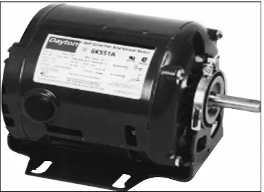
AC induction motor is the most common motor used in industry and mains powered home applicants. Induction motors are also sometimes called squirrel cage motors because the appearance of early rotors. This type of motors are the most common type of industrial AC electric motor, being rugged and requiring neither a separate DC power source nor slip-rings. AC induction motors offer users simple, rugged construction and easy maintenance. An AC induction motor consists of two basic assemblies; stator and rotor, and is analogous to an AC transformer with a rotating secondary. The motor’s name comes from the alternating current (AC) induces into the rotor by the rotating magnetic flux produced in the stator. Motor torque is developed from interaction of currents flowing in the rotor bars and the stator's rotating magnetic field.[5]
Figure 2.4: Example of AC motor
2.2.2 DC Motor
![Figure 2.1: Radiation pattern in a rectangular azimuth plot presentation.[3]](https://thumb-ap.123doks.com/thumbv2/123dok/681075.84111/21.612.270.449.372.551/figure-radiation-pattern-rectangular-azimuth-plot-presentation.webp)
![Figure 2.3: Test setup for single-axis polar pattern measurement.[4]](https://thumb-ap.123doks.com/thumbv2/123dok/681075.84111/22.612.175.478.243.402/figure-test-setup-single-axis-polar-pattern-measurement.webp)