It is essential to observe the instructions in this safety manual if the device is to be used in safety-relevant applications. If in doubt about the interpretation, please refer to the German version of the safety manual or contact Turck directly. For safety-relevant applications, the SIL registration card supplied with the device must be completed in full by the user and must be returned to Turck.
The user is obliged to ensure that the device is used in accordance with applicable regulations, standards and laws. When the device is operating, make sure that the power supply is within the specified voltage range. If errors occur in the device that cause a switch to a defined safe state, measures must be taken to maintain the safe state during continued operation of the entire control system.
The device must be replaced immediately if the terminal is faulty or the device has any visible faults. Normal operation: The device sends the 4...20 mA current signals with a tolerance of 2 % of the final value from the input to the output. High trip (on short circuit): The device switches to the safe state at an input current of >.
Certain characteristic values apply to the use of the output in safety-related functions.
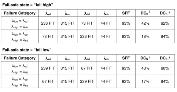
Safety characteristic values
FMEDA assumptions
Hardware architecture
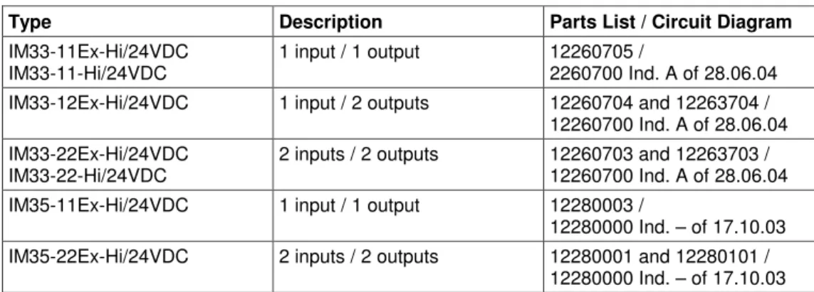
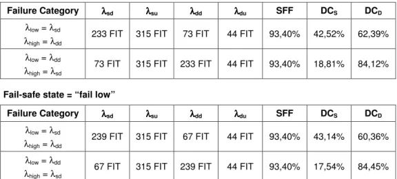
Characteristic values for IM33-… isolating transducers
Recurrent function tests
Useful life
Special regulations and restrictions
Mounting
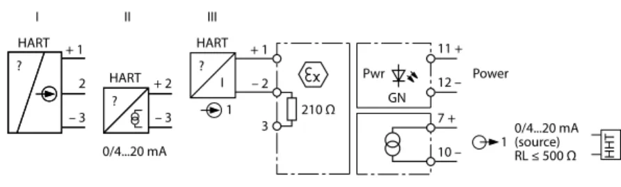
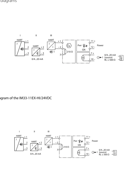
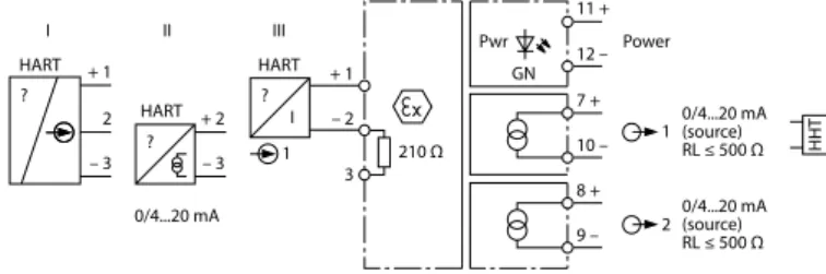
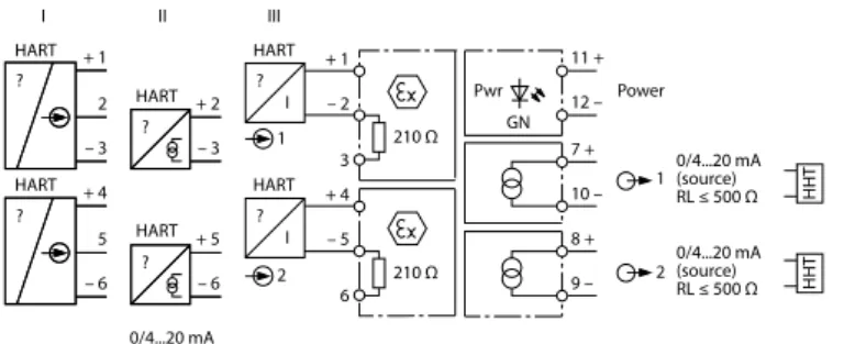
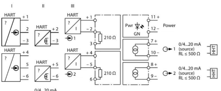
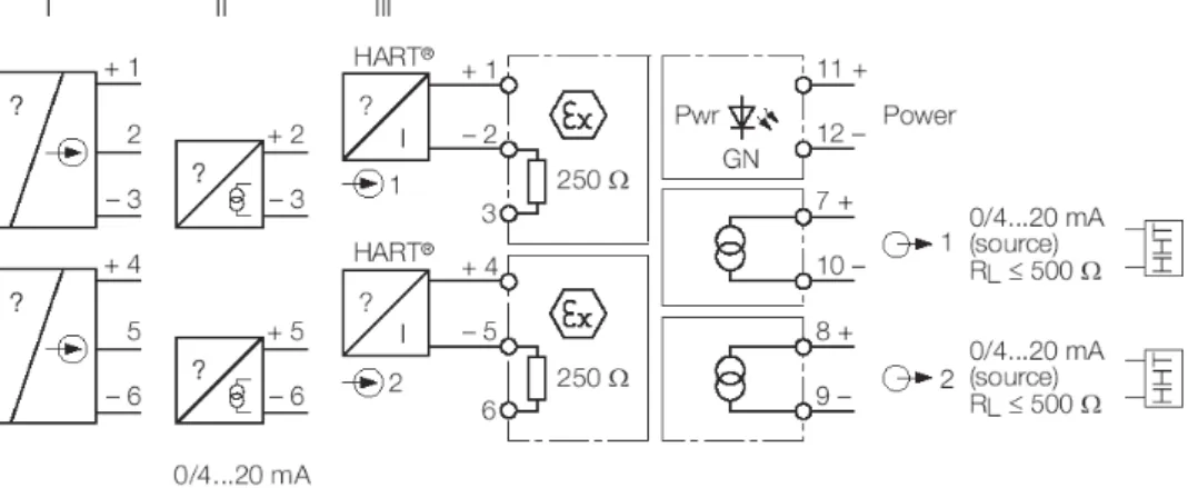
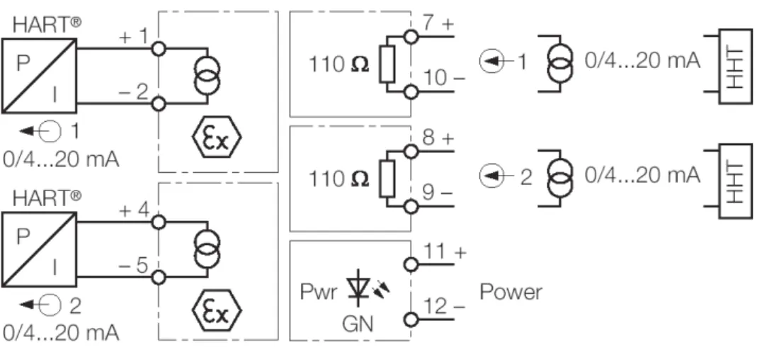
Connection
Wiring diagrams
Commissioning
Selecting transmitters
Troubleshooting
Maintenance
Repair
Returning devices
Decommissioning
Withdrawing from service
Failure Modes, Effects and Diagnostic Analysis
Management summary
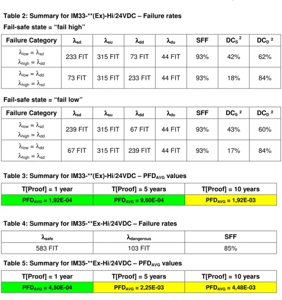
The boxes marked in yellow ( ) mean that the calculated PFDAVG values are within the allowed range for SIL 2 according to table 2 of IEC 61508-1, but do not meet the requirement of not exceeding 10% of this range do not claim, i.e. The two channels on a redundant board will not be used to increase the hardware fault tolerance needed for a higher SIL, as they contain common components. A user of the Isolating Transducers IM33-**(Ex)-Hi/24VDC and Analog Signal Transmitters IM35-**Ex-Hi/24VDC can use these failure rates in a probabilistic model of a safety instruments function (SIF) to to determine suitability partly for safety-instrument-system (SIS) used in a specific safety integrity level (SIL).
Failure rates are valid for the useful life of IM33-**(Ex)-Hi/24VDC isolation transmitters and IM35-**Ex-Hi/24VDC analog signal transmitters, estimated to be between 8 and 12 years (see Appendix 2). It is important to understand that "no effect" failures are included in the category of "safe undetected" failures according to IEC 61508. Note that these failures in themselves will not affect the reliability or safety of the system and should not be included in trips false calculations.
1 Purpose and Scope
2 Project management
Roles of the parties involved
Standards / Literature used
- Documentation provided by the customer
3 Description of the analyzed module
Isolating Transducers IM33-22Ex-Hi/24VDC
Analog Signal Transmitter IM35-22Ex-Hi/24VDC
4 Failure Modes, Effects, and Diagnostic Analysis
Description of the failure categories
Methodology – FMEDA, Failure rates .1 FMEDA
- Failure rates
- Assumptions
- Example explaining the behavior of the safety logic solver
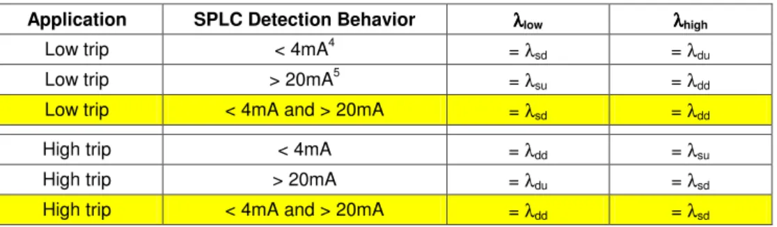
The application program in the safety logic solver is constructed so that low and high error errors are detected regardless of the effect, safe or unsafe, on the safety function3. Low Trip: The safety function enters a predefined safe state when the process value is below a predefined low setpoint. High Trip: The safety function enters a predefined safe state when the process value exceeds a predefined high setpoint.
Fail Low and Fail High failures may or may not be detected by an associated logic resolver. The SPLC detection behavior in Table 6 represents the under-range and over-range detection capability of the associated security logic solver. In this analysis it is assumed that the safety logic solver is able to detect under-range and over-range currents, hence the yellow highlighted behavior is assumed.
5 Results of the assessment
Isolating Transducers IM33-**(Ex)-Hi/24VDC
PFDAVG was calculated for three different sample test times using the Markov model as described in Figure 3.
Analog Signal Transmitters IM35-**Ex-Hi/24VDC
1oo1 structure
6 Terms and Definitions
7 Status of the document
- Liability
- Releases
- Release Signatures
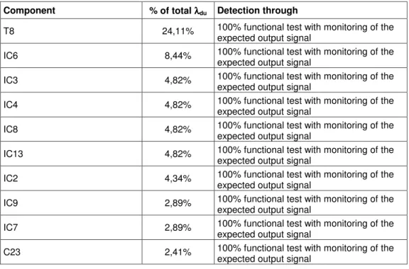
- Possibilities to reveal dangerous undetected faults during the proof test
- Possible proof tests to detect dangerous undetected faults Isolating Transducers
- Impact of lifetime of critical components on the failure rate Although a constant failure rate is assumed by the probabilistic estimation method (see section
- subsidiaries and 60 representations worldwide!
This means determining how dangerous undetected defects observed during FMEDA can be detected during proof testing. 2 Send a HART command to the isolation transducers to go to the high alarm current output and verify that the analog current reaches this value. 3 Send a HART command to the isolation transducers to go to the low alarm current output and check that the analog current reaches this value.
5 Remove the bypass of the safety PLC or otherwise restore normal operation. This test will detect about 50% of possible "du" faults in the isolation converters. 1 Bypass the safety PLC or take other appropriate steps to avoid a false trip 2 Perform Proof Test 1. This requires that the transmitter has already been tested without the Isolating Transducers and no longer contains any dangerous undetected errors.
5 Remove the bypass from the safety PLC or otherwise restore normal operation. This test will detect approx. 99% of possible "you" errors in the isolating transducers. 2 Provide a 4mA control signal to the analog signal transmitter to open/close the valve and check that the valve is open/closed. However, it requires that the valve has already been tested without the analog signal transmitter and no longer contains dangerous undetected faults.
3 Give a 4.20 mA control signal in 1 mA steps to the analog signal transmitter to open/close the valve and verify that the valve opens/closes accordingly. This requires that the valve has already been tested without a repeater and no longer contains any dangerous undetected defects. Useful life is highly dependent on the component itself and its operating conditions - temperature in particular (electrolyte capacitors can be very sensitive, for example).
Therefore, it is obvious that the PFDAVG calculation is only valid for components that have this constant domain, and that the validity of the calculation is limited to the lifetime of each component. It is assumed that early failures are detected to a large percentage during the installation period, and therefore the assumption of a constant failure rate during the service life is valid. Since no aluminum electrolytic capacitors are used, the only limiting factor in terms of system life is tantalum electrolytic capacitors, which have a life of about 57 years.