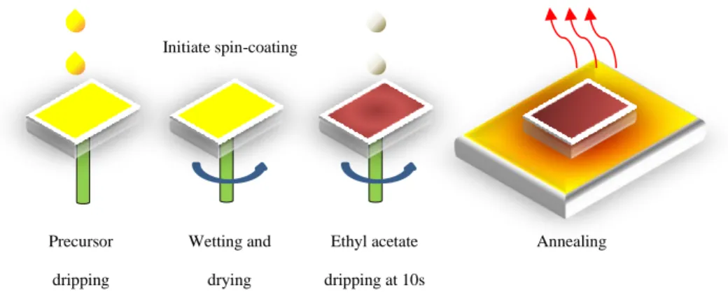
Here, this work prepared MAPbI3 films using antisolvent-assisted spin coating and encapsulated them with poly(methyl methacrylate) (PMMA) by spin coating PMMA in ethyl acetate on the films. 108 Figure 4.19: Appearance of C-MAPbI3 films with different. f) Magnified image of 2 mg/mL PMMA encapsulated C-MAPbI3 film annealed for 180 min.
General Introduction
This high temperature annealing process prevented the metal oxide sols from being directly applied to perovskite layer, as their annealing process could thermally degrade the perovskite film. Therefore, the thermal stability of MAPbI3 must first be improved before these low-temperature metal oxide sols can be annealed on top of it.
Importance of the Study
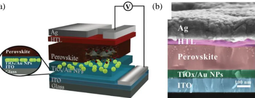
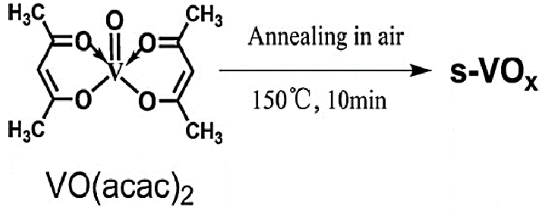
Vanadium oxide (VOx) sol aged from vanadyl acetylacetonate (VO(acac)2) in isopropanol was encapsulated with PMMA and caffeine added MAPbI3 film and annealed at 150 °C for 20 min. The feasibility of annealing metal oxide sol on the film should open a new path for the fabrication of all metal oxide CTL PSCs via sol route, greatly improving the device operating stability.
Problem Statement
Aim and Objectives
To determine the effects of PMMA concentration on thermal stability of caffeine added MAPbI3 film. To investigate the feasibility of annealing VOx sols on MAPbI3 film after thermal stability enhancement provided by PMMA and caffeine.
Outline of Dissertation
Introduction
The discussion then goes on to highlight the limitations of the current perovskite-compatible metal oxide CTL deposition process and propose low-temperature solution-processed metal oxide sols as an alternative. Since these metal oxide sols require 150 °C annealing temperature to form compact CTLs, thermal stability of MAPbI3 films at this temperature is reviewed.
Disadvantages of Organic CTLs
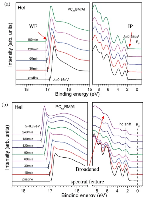
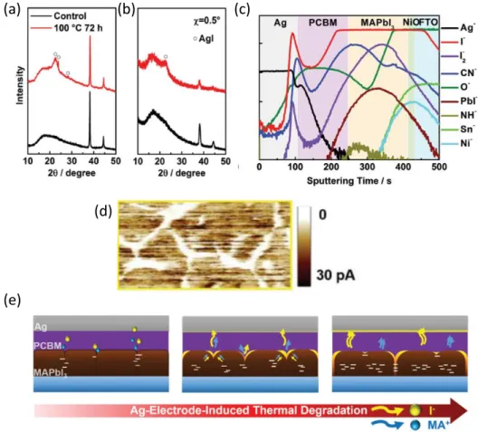
Therefore, this work provided further evidence on weak ion migration barrier properties of Spiro-OMeTAD. It was observed that the device heated with Spiro-OMeTAD (without Au counter electrode) significantly reduced the PCE, specifically due to reduction in fill factor (FF).
Advantages of Metal Oxide CTLs
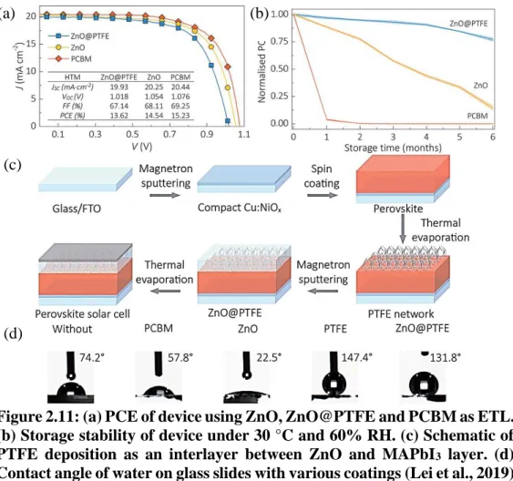
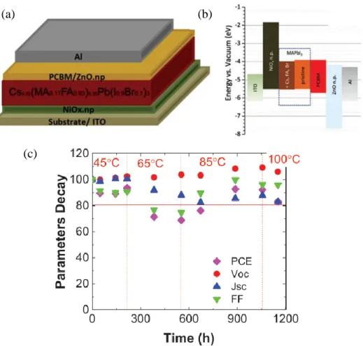
To further extend the stability, hydrophobic polytetrafluoroethylene (PTFE), deposited via thermal evaporation, was used as an intermediate layer between the ZnO and MAPbI3 layers (Figure 2.11(c)). In addition, a slight improvement in PCE was observed after the thermal stress test (Figure 2.13(b)), presumably due to improved crystallinity due to Ostwald ripening.
Limitations of Current Methods for Metal Oxide CTL Deposition on Perovskite Film
Unfortunately, there is a lack of works that deposited metal oxide CTL directly on perovskite using the low-temperature metal oxide solar route, probably due to the annealing process of the solar that is incompatible with the thermal stability of the perovskite film. Regardless, since this work aims to incorporate metal oxide sols as CTL on perovskite, it will be appropriate to discuss some of the low temperature metal oxide sols that have recently been used as successful CTL under the perovskite layer.
Low-Temperature Solution-Processed Metal Oxide as CTL
- SnO 2
- TiO 2 or TiO x
- CeO x
- Other Low-Temperature Processed Metal Oxides
ETL with CeOx via sol-gel route. The sol-gel was prepared by dissolving cerium(III) acetylacetonate hydrate in ethanol and applied to FTO substrate by spin coating followed by annealing at 150 °C for 15 min. Zilberberg et al. 2011) used vanadium triisopropoxide dissolved in isopropanol to Prepare V2O5 sol gel. In the work of Alsulami et al. 2016), the V2O5 HTL prepared from the same vanadium triisopropoxide in isopropanol for 30 min at an even lower temperature at 100 °C was annealed on ITO substrate.
In the work of Mahmud et al. 2017), ZnO with a processing temperature of 140 °C was used as ETL in conventional PSC.
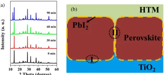
MAPbI 3 Thermal Stability at 150 °C
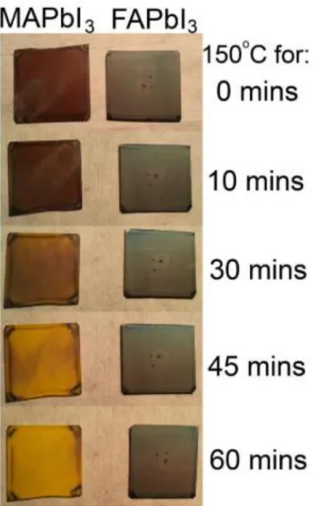
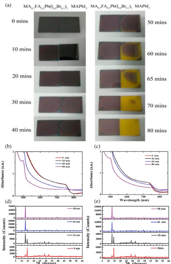
This was due to the excessive amount of poorly conducting PbI2 formation in the film, as reflected in Figure 2.23(a) for the 90 min annealed sample. As shown in Figure 2.25, the MAPbI3 film showed signs of thermal degradation after 50 minutes and completely degraded to yellow PbI2 after 80 minutes. In contrast, the FA-reinforced perovskite film still retained a small amount of perovskite phase even after 80 min (Figure 2.25 (e)).
When the annealing duration was extended to 20 min, the MAPbI3 film began to experience thermal decomposition and can be observed by the formation of pinholes on the film (Figure 2.28(c)).
PMMA and Caffeine Potential in Enhancing MAPbI 3 Thermal Stability
Their C-AFM analysis revealed strong hysteresis behavior (Figure 2.32 (b)) in GB when measuring the dark current. TMTA was able to passivate GB defects by forming a coordinative bond with I− Pb2+ deficient sites on GBs via its carbonyl groups (C=O), as shown in Figure 2.33 (c). This improved the thermal stability of the MAPbI3 film as the PSC with cross-linked TMTA retains more than 80% of the initial PCE even after thermal stress at 85 °C 1000 h (Figure 2.33(e)).
2018) also used PMMA interlayers to passivate the interfacial defects of ETL|perovskite and HTL|perovskite (Figure 2.35(a)).
Summary of Literature Review
Once the thermal stability improvement has been identified, this work then attempts to anneale vanadium oxide sol with an annealing temperature of 150 °C for 20 minutes. This should pave the way to fabricate all metal oxide CTL-based PSCs in the future if the metal oxide sol annealing process does not degrade the MAPbI3 perovskite layer.
Preparation of MAPbI 3 Precursor Solution
Deposition of MAPbI 3 Film and Thermal Stressing
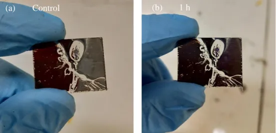
The film was then annealed on the hotplate at 100 °C for 5 min to evaporate residual solvents and darkened. Since the PMMA solution was malignant, a pipette tip was used to conduct and wet the MAPbI3 completely. Then, heating of the film was resumed at 100°C for 5 minutes. Refer to this sample as a control film.
The deposition of the C-MAPbI3 film and the thermal stress were the same as the P-MAPbI3 film, except for the precursor preparation mentioned in Section 3.1.
VO x Deposition on MAPbI 3
To investigate how different concentrations of PMMA can affect the thermal stability of the C-MAPbI3 film, different concentrations of PMMA solution (mg/mL) in ethyl acetate were prepared. The VOx sol on top of the film was then subjected to annealing at 150 °C for 20 min to evaporate any remaining solvent (isopropanol and acetylacetonate).
Characterizations
- Physical Appearance Assessment of the Films
- XRD characterization
- SEM and EDX Analysis
- UV-Vis Analysis
For P-MAPbI3 films, the top view of the films was subjected to SEM and EDX analyzes (Hitachi S-3400N equipped with EDAX EDX detector). Prior to the top-down SEM and EDX analyses, the films were immersed in chlorobenzene for 10 minutes to remove the PMMA encapsulation. For C-MAPbI3 films, the top view of the film was subjected to SEM and EDX analyses, and the cross-sectional view was subjected to SEM analysis only.
For each hour of heating, the samples were placed inside the cuvette and subjected to ex-situ UV-Vis characterization (Cary 100-UV-Vis Spectrophotometer).
Overall workflow
Introduction
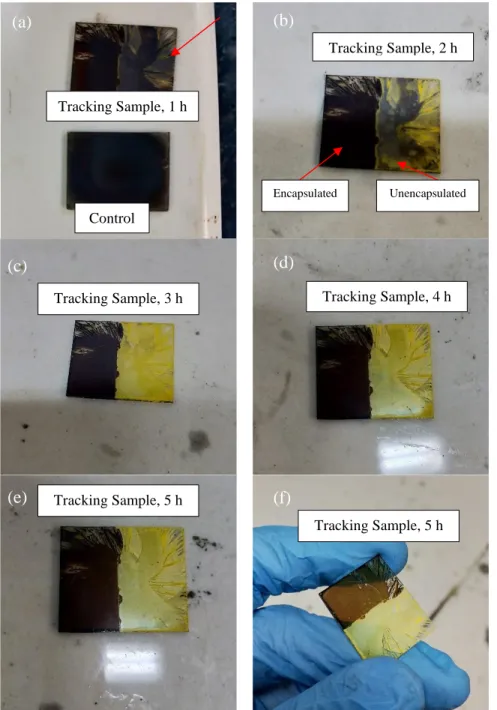
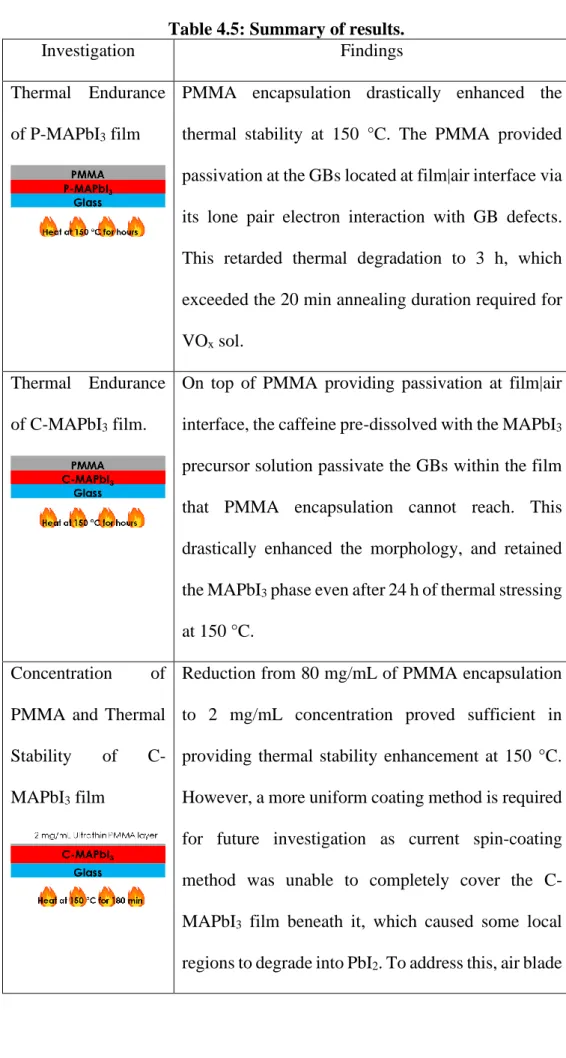
Thermal Endurance of P-MAPbI 3 Film
- Physical Appearance Assessment
- XRD Analysis of P-MAPbI 3 Film
- SEM Analysis of P-MAPbI 3 Film
- UV-Vis Spectroscopy Analysis of P-MAPbI 3 Film
- EDX Analysis of P-MAPbI 3 Film
As shown in Figure 4.4(b), rice-shaped granules began to precipitate from MAPbI3 granules in a region of the 3 hour sample. As a result, PbI2 presence was significant and is reflected in the 5 h XRD analysis (Figure 4.2), accompanied by the noticeable bleaching of the dark brown color of the film (Figure 4.1f). As shown in Figure 4.5(a), as the annealing time increased, the absorbance from 450 nm to 550 nm decreased accordingly.
According to Figure 4.5(b), the edge of the MAPbI3 band was observed at around 750 nm regardless of the annealing time.
Thermal Endurance of Caffeine Boosted MAPbI 3 Film
- Physical Appearance Assessment
- XRD Analysis of C-MAPbI 3 Film
- SEM Analysis of C-MAPbI 3 Film
- UV-Vis Spectroscopy Analysis of C-MAPbI 3 Film
- EDX Analysis of C-MAPbI 3 Film
- Thermal Stability of 24 h C-MAPbI 3 Film
In contrast to the XRD pattern of P-MAPbI3 film (Figure 4.2), the C-MAPbI3 peak at 31.8° corresponding to (222) remained throughout the duration of annealing. It can be seen from Figure 4.8(a) that the control film (heated to 100 °C for 10 min) consisted of many small individual grains similar to the P-MAPbI control sample (Figure 4.3(a)). Consistent with the top SEM view, the cross-sectional view (Figure 4.8(b)) shows that the ~ 380 nm thick C-MAPbI3 film is composed of multilayered small aspect ratio (<1) grains.
In fact, Figure 4.10(c) confirms the large aspect ratio (>1) of the grains adhering to the PMMA layer.
Investigation of Concentration of PMMA and Thermal Stability of C-MAPbI 3 film
Physical Appearance Assessment
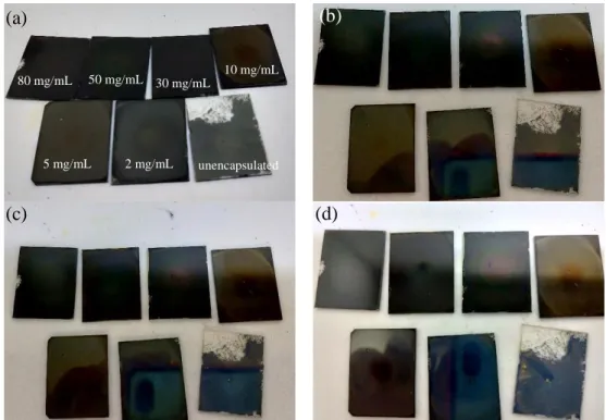
As shown in Figure 4.19(a), different concentrations of PMMA resulted in different finishes of the C-MAPbI3 films. The encapsulated samples retained the dark brown color (Figure 4.19(d–g)) regardless of the PMMA concentration. Impressively, the 2 mg/ml sample showed no discernible changes in its physical appearance, maintaining its mirror-like reflectance throughout the 180 minute (3 hour) annealing time, as shown in Figure 4.19(g).
However, a closer look at the 2 mg/mL PMMA encapsulated film in Figure 4.19(h) revealed a yellow PbI2.
XRD Analysis of C-MAPbI 3 Film with Different PMMA Encapsulation Concentrations
SEM analysis of 2 mg/mL PMMA Encapsulated C-MAPbI 3 Film
The darker region highlighted by the yellow arrow represents PMMA, while the brighter region highlighted by the red arrow represents the MAPbI3 grains.
Thermal Stability Enhancement Mechanism
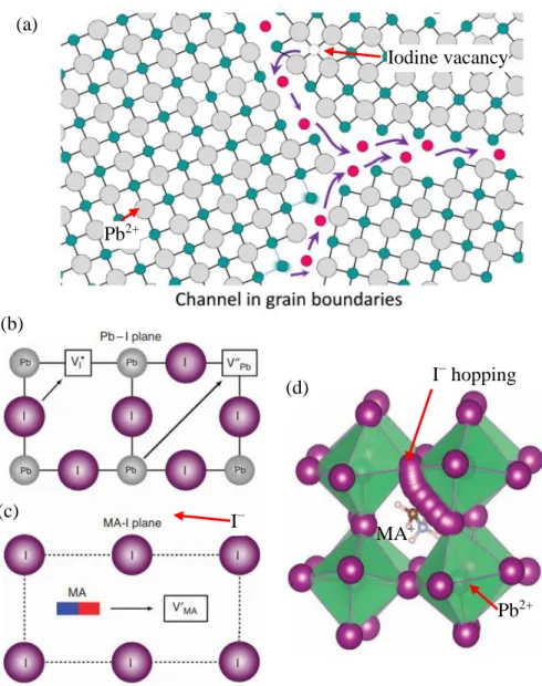
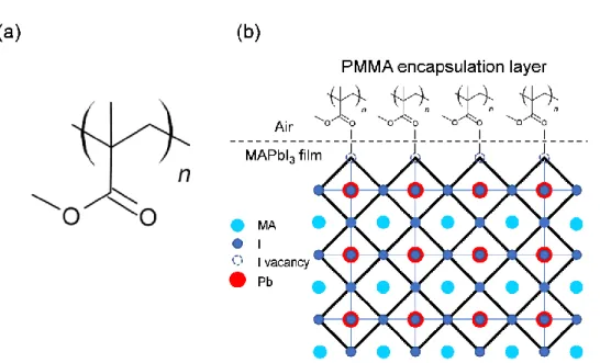
2016) also showed that the ion mobility at the GBs is significantly faster than that of the ions in the bulk of the grain, which accounted for the hysteresis behavior reported during forward and backward scans of the MAPbI3 solar cell. In addition, it also prevented moisture ingress and interaction at the GBs during thermal stress, which can cause rapid degradation (McKenna et al., 2017; Messegee et al., 2019). The illustration of caffeine rendering the GBs in the film passive together with PMMA at the interface between film and air is shown in Figure 4.23.
Similarly, polyacrylic acid can also passivate GBs in MAPbI3 film deposited using doctor blade (N. Li et al., 2019).
Other molecules containing carbonyl groups such as polyethylene oxide can also form coordinative bonding with Pb2+ defect site at GBs (Kim et al., 2018). Solvent screening test performed by Chu et al. 2018) showed that dripping IPA onto MAPbI3 did not damage the coating. A possible reason may be due to the release of acetylacetone from the VO(acac)2 in the IPA solution after VOx sol formation (Nenashev et al., 2015; Tan et al., 2012).
Nevertheless, both did not resolve PbI2, which may be due to their weak coordination with Pb2+ (Y. Wang et al., 2017).
Summary of Result
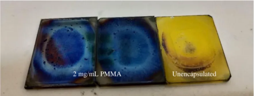
In addition to PMMA providing passivation at the film-air interface, the caffeine pre-dissolved with the MAPbI3. This dramatically improved the morphology and preserved the MAPbI3 phase even after 24 hours of thermal stress at 150 °C. It has been proven that VOx spin coating is detrimental to the C-MAPbI3 film, because the solvents from VOx sol inhibit the degradation of the movie could speed up.
Fortunately, only 2 mg/ml PMMA encapsulation protected the C-MAPbI3 from interacting with the solvents during spin coating and improved the thermal stability of the C-MAPbI3 film.
Conclusions
Recommendations for future work
Low temperature solution processed vanadium oxide as hole transport layer for efficient and stable perovskite solar cells. Low-temperature treated ZnO thin film as an electron transport layer for efficient perovskite solar cells. V2O5-PEDOT: PSS double layer as hole transport layer for highly efficient and stable perovskite solar cells.
Low temperature based TiO2-SnO2 bilayer electron transport layer for high performance perovskite solar cells.