Design of Microcontroller Based Dual Braking Mechanism for Micro-Wind Turbine
by
MUHAMMAD ZULFADLI BIN ZOLKIFLY (1632221975)
A dissertation submitted in partial fulfilment of the requirements for the degree of Master of Science Electrical Power Engineering
School of Electrical System UNIVERSITI MALAYSIA PERLIS
2017
© Thi
s i tem
is pr ot ec ted by
or igi nal
c opy
right
ii
ACKNOWLEDGEMENTS
A lot of people had extended their helping hands in the working of this project.
Without their help, I could not possibly imagine what the projects would be in the end.
Therefore, I would like to take this opportunity to express my deepest gratitude to those who had given their help either directly or indirectly into the process of completing this project.
First of all, I would like to take this opportunity to say thank supervisor, Dr Norkharziana Binti Mohd Nayan for all the help and support she had given to me. I also want to thank her for all the guidance that had given on me to completing this project, especially guideline in finishing the thesis for the project which I am not well experienced in that. With her help in the thesis I finally finished completing the thesis for this project. I would also want to thank my parent and my other family member for their support, love and care during the progress of this project.
Last but not least, I want to thank all my friends that had supported and helped me during the process of completing this semester project whether their help was useful or not.
© Thi
s i tem
is pr ot ec ted by
or igi nal
c opy
right
iii
TABLE OF CONTENTS
PAGE
THESIS DECLARATION i
ACKNOWLEDGEMENTS ii
TABLE OF CONTENTS iii
LIST OF TABLE vi
LIST OF FIGURES vii
LIST OF ABBREVIATIONS x
ABSTRAK xi
ABSTRACT xii
CHAPTER 1 1
1.1 Background 1
1.2 Problem statement 2
1.3 Objective 3
1.4 Scope of project 3
1.5 Thesis outline 4
CHAPTER 2 5
2.1 Introduction 5
2.2 Wind classification and wind profile 6
2.3 Operation of wind turbine 9
2.4 Yaw control 10
2.5 Furling mechanism 11
© Thi
s i tem
is pr ot ec ted by
or igi nal
c opy
right
iv
2.6 Dynamic braking 12
2.7 Control system 13
2.8 PID control 15
2.9 ITAE tuning 16
2.10 Conclusion 17
CHAPTER 3 18
3.1 Modeling of output winds power 18
3.2 Linearization of wind turbine 19
3.3 Modelling DC generator 22
3.4 Modeling of DC motor 23
3.5 PID tuning via ITAE 25
3.6 Prototype specification 29
3.7 Drives circuit for yaw control and dynamic resistor 30
CHAPTER 4 32
4.1 Hardware setup 32
4.2 Experimental result 34
4.3 Analysis of performance of dynamic braking system 35
4.4 Analysis yawed wind turbine operation 37
4.5 ITAE tuning 38
4.6 Overspeed protection and speed regulation 40
4.7 Comparison between yaw braking and dual braking system 42 4.8 Analysis of braking system in full stop operation 44
4.9 Discussion 45
4.10 Conclusion 46
CHAPTER 5 47
© Thi
s i tem
is pr ot ec ted by
or igi nal
c opy
right
v
5.1 Summary 47
5.2 Future work 48
REFERENCE 49
APPENDIX – A 52
APPENDIX – B 53
© Thi
s i tem
is pr ot ec ted by
or igi nal
c opy
right
vi
LIST OF TABLE
Table No Page
Table 2.1 Classification of wind 7
Table 2.2 Roughness length derived from terrain classification 8
Table 3.1 ITAE criteria for step input 25
Table 3.2 Mode of operation of H-bridge 30
Table 4.1 Dynamic braking for 63% 36
Table 4.2 Dynamic braking for 30% 36
Table 4.3 Controller gain 40
Table 4.4 Overspeed testing 41
© Thi
s i tem
is pr ot ec ted by
or igi nal
c opy
right
vii
LIST OF FIGURES
Figure No Page
Figure 2.1 Region scheme operation for wind turbine 9
Figure 2.2 Yawed wind turbine 10
Figure 2.3 Furling wind turbine 11
Figure 3.1 Coefficient of torque of micro wind turbine 19
Figure 3.2 Block diagram of wind turbine 21
Figure 3.3 Schematic of DC motor 23
Figure 3.4 Micro-wind turbine system prototype 29
Figure 3.5 H bridge drives 30
Figure 3.6 Dynamic braking resistor 31
Figure 4.1 Full diagram of the proposed system 32
Figure 4.2 Hand held anemometer 33
Figure 4.3 Controller braking system 33
Figure 4.4 Micro wind turbine during experiment 34
Figure 4.5 Speed measurement for right and left position of micro wind turbine 34
Figure 4.6 Transient respond of system 35
Figure 4.7 Yawed wind turbine 37
Figure 4.8 Overspeed test 40
Figure 4.9 Speed regulation 42
Figure 4.10 Over speeding protection by using yaw braking 43
Figure 4.11 Dual braking system 43
Figure 4.12 Stop condition wind turbine 44
© Thi
s i tem
is pr ot ec ted by
or igi nal
c opy
right
viii
LIST OF SYMBOL
kp Proportional gain
k
i Integral gaink
d Derivatives gaink
c Controller gainT
s Settling time
n Damping frequency Damping ratio
Tip speed ratioC
T Coefficient of torqueCp Coefficient of power
𝐽 Moment of inertia
𝐵 coefficient of Viscosity 𝐴 Swept area of wind turbine
𝑟 Radius of blade
𝜌 Density of air
© Thi
s i tem
is pr ot ec ted by
or igi nal
c opy
right
ix
𝐼 Current
𝑉 Voltage
𝐸 Induce voltage
𝑘∅ Voltage constant
𝑅 Total resistance
© Thi
s i tem
is pr ot ec ted by
or igi nal
c opy
right
x
LIST OF ABBREVIATIONS
PID Proportional, integrals and derivatives USB Universal Serial Bus
Rpm Rotational per minute ITAE Integral time absolute error
MOSFET Metal oxide semiconductor field effect transistor
© Thi
s i tem
is pr ot ec ted by
or igi nal
c opy
right
xi
Mereka Pengawal Mikro Berdasarkan Mekasima Dual untuk Kincir Angin Mikro
ABSTRAK
Kajian ini membentangkan mekanisma pembrekan dual yang mengandungi brek dinamik dan juga pengawalan rewang. Kedua-dua mekanisme ini dapat memberikan perlindungan kepada kincir angin mikro daripada beroperasi melebihi had laju maksimum dan turut berfungsi sebagai pengawal kelajuan. Pembrekan konvensional bagi kincir angin mikro menggunakan sistem pembrekan yang pasif. Isu yang berkaitan dengan sistem pembrekan yang pasif mempunyai lingkungan kelajuan angin yang terhad. Oleh itu, matlamat kajian ini ialah melanjutkan lingkungan operasi kincir angin mikro dan juga menghalangnya daripada melebihi had kelajuan maksimum. Kajian ini menggunakan "The Proportional Integral Derivatives (PID)" untuk mengawal mekanisme pembrekkan yang berteraskan kriteria "Integral Time Absolute Error (ITAE)" bagi menentukan nilai PID. Mekanisme yang dicadangkan menunjukan keupayaannya dalam mengekalkan kelajuan putaran dibawah had maksimum apabila kelajuan angin dinaikan dari 4.8 hingga 5.2 m/s tanpa memerlukan operasi penutupan
© Thi
s i tem
is pr ot ec ted by
or igi nal
c opy
right
xii
Design of Microcontroller Based Dual Braking Mechanism for Micro-Wind Turbine
ABSTRACT
The work proposes dual braking mechanism. It consisted of dynamic braking and yaw control. Both mechanism is used to provide safety to the micro-wind turbine. It protects from over speed and also functioning as speed regulator. A conventional braking system for micro wind turbine uses passive braking system. The limited wind speed range is an issue when to deal with the passive braking system. Therefore, the goal of this study is to extend the range of operation of micro wind turbine and preventing it from over speed condition. The Proportional Integral Derivatives (PID) algorithm is used to control the braking mechanism based on Integral Time Absolute Error (ITAE) criteria to determine its coefficient. The proposed mechanism able to maintain rotational speed under the maximum limit when wind speed increase from 4.8- 5.2 m/s without the needs to shutdown operation.
© Thi
s i tem
is pr ot ec ted by
or igi nal
c opy
right
1 CHAPTER 1
INTRODUCTION
1.1 Background
This paper introduces the braking system in multi-rotor micro-wind turbine where the power generation is below 1 kW. The multi-rotor configuration is introduced to overcome the difficulties of producing a larger blade with a specific characteristic namely low mass with high strength capabilities. This is due to lack of technology advancement (Habib, Ibrahim, & Rafukka, 2016). These requirements involve with upscaling theory when power generation is scaled with the size of the blade (Troldborg
& Sørensen, 2012). The upscaling theory has a limitation because the mass of wind turbine increased in cubic. Meanwhile, power generated only posed increase in the square .The idea of installing small multi-rotor micro-wind turbine to boost power generation that equivalent to the single unit large wind turbine (Velázquez et al., 2014).
Therefore, due to smaller blade size and generator, the mass was significantly reduced.
In addition, it also allows to use single support structure compare with an individual wind turbine that configured in a wind farm. For a micro wind turbine, its output power is less comparing with small scale wind turbine (Ledo, Kosasih, & Cooper, 2011). Due to low power generation, application focused in standalone power system such as charging battery (Li, Reynolds, & Fergal, 2011).
© Thi
s i tem
is pr ot ec ted by
or igi nal
c opy
right
2
The main problem in a multi-rotor wind turbine is over speed condition which each rotor can have different rotational speed. Due to high-speed condition bearing of the rotor will wear faster and produce abnormal temperature. This will increase the risk of fire especially for a wind turbine that used flammable fiberglass resin and oil deposited in wind turbine nacelle (Uadiale et al., 2014). A direct-drive wind turbine requires less rotating component that contribute to the risk of fire which will reduce the risk and improve reliability (Polinder et al., 2013) . Normally, for small and micro-scale wind turbines, a fixed pitch is used to reduce the complexity of the system and cost.
1.2 Problem statement
Micro wind turbine expected to harvest a wind power from the low range of wind speed. In term of power generation perspective, high wind speed is good because wind turbine can produce more electrical power. However, when micro wind turbine operate at high wind speed region, it has a major drawback such as shorten it bearing life span and increase possibility for support structure failure due to vibration. For multi-rotor configuration, the swept area of wind turbine also increased. During gust wind, the wind speed can rise up to 7.71 m/s or more in a short period of time. This may cause one of the wind turbines experiences different wind flow from one another. As result, these causes one of the wind turbine to accelerate thus may lead to over speed condition. This condition requires control mechanism to regulate each of rotor speed at safe level when wind speed suddenly exceed rated speed
© Thi
s i tem
is pr ot ec ted by
or igi nal
c opy
right
3 1.3 Objective
1) To develop over speed protection system for micro wind turbine. This is to ensure micro-wind turbine keep protected against high wind speed.
2) To develop control system that able to regulate micro-wind turbines speed within safe limit.
1.4 Scope of project
The scope of this project is limits to a braking system which involve with yaw control and dynamic braking mechanism for multi-rotor configuration. The controller is designed based on Proportional Integral Derivatives (PID) for both mechanisms. The micro wind turbine used consisted of DC generator that rated at 24V. The range of wind speed that controller that can cover to prevent wind turbine from overspeeding in range 0-6.2 m/s.
© Thi
s i tem
is pr ot ec ted by
or igi nal
c opy
right
4 1.5 Thesis outline
Chapter 1 introduces the background of the micro wind turbine and multi-rotor configuration. Chapter 2 is about review yaw mechanism, dynamic braking and PID controller by using Integral Time Absolute Error (ITAE) tuning. Chapter 3 involve with linearization of the wind turbine by using Taylor series and PID controller design based on ITAE tuning. Chapter 4 is about braking mechanism and controller testing. Chapter 5 is a discussion about the significant result and finding on braking system of micro wind turbine and controller system.
© Thi
s i tem
is pr ot ec ted by
or igi nal
c opy
right
5 CHAPTER 2
LITERATURE REVIEW
2.1 Introduction
The micro-wind turbine is defined as a micro power generation wind turbine usually under 1 kW (Drumheller et al., 2015). Normal operation of a micro wind turbine is within 2 to 4.5 m/s range will produce voltage up to 4 V. One of the distinguishing feature of micro-wind turbine is smaller in size as compare with small-scale wind turbine. This micro-wind turbine is configured in the array with the same structure which need a braking mechanism to control the operation speed and also for full stop operation. The braking system can be implemented by studying some techniques that were used in medium and large wind turbine to protect them against over speed that is caused by high wind speed. The analysis of wind speed is needed to set the range of cut- off speed due to mechanical constraints of the micro-wind turbine.
© Thi
s i tem
is pr ot ec ted by
or igi nal
c opy
right
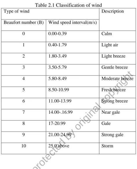
6 2.2 Wind classification and wind profile
The mechanical constraint that imposed on the wind turbine due to wind characteristic is non-uniform flow in nature. The wind speed depends on several factors namely the height, atmospheric pressure, and surrounding terrains. Beaufort scale was developed in 1805 by Sir Francis Beaufort to provide the classification of wind according to the speed. Wind speed can be computed by using equation 2.1 according to Beaufort number.
v = 0.836 B32 ( 2.1)
v is the velocity of wind and B is the Beaufort number.
Table 2.1 shows that estimation of wind speed according to Beaufort number.
According to a study conducted by Razali et al. (2010), when wind speed that exceeds 21 m/s, it can have a disaster impact on the wind turbine. One of the criteria for support structure of wind turbine, it must able to withstand high exerting forces and cyclic loading with certain limit without any sign of mechanical failure (Muskulus & Schafhirt, 2014). These criteria make micro-wind turbine range of operation is limited if low mechanical strength material is used. However, wind speed in the range from gale to storm is a rare case that occurs in Malaysia unless during tropical storm or typhoon.
© Thi
s i tem
is pr ot ec ted by
or igi nal
c opy
right
7
Table 2.1 Classification of wind
Type of wind Description
Beaufort number (B) Wind speed interval(m/s)
0 0.00-0.39 Calm
1 0.40-1.79 Light air
2 1.80-3.49 Light breeze
3 3.50-5.79 Gentle breeze
4 5.80-8.49 Moderate breeze
5 8.50-10.99 Fresh breeze
6 11.00-13.99 Strong breeze
7 14.00-.16.99 Near gale
8 17-20.99 Gale
9 21.00-24.99 Strong gale
10 25.0 above Storm
According to Albani, Ibrahim, & Hamzah (2013), the highest average wind speed across Malaysia from the year 2007 to 2011 at 10 meter height is 3.4 m/s during the northeast monsoon. This condition will not affect the normal operation of the wind turbine except during storm or gust wind blow. Furthermore, wind speed will increase when height levitated above the ground especially when micro-wind turbine is installed in a tall building or in the height terrain. Often the data on high-altitude is not available for analysis thus predicted model is used.
© Thi
s i tem
is pr ot ec ted by
or igi nal
c opy
right
8
There are several methods that can be used to estimate the wind speed at a certain height such as logarithmic wind profile method that was describes by Noram I. Ramli (Ramli, Ali, Saag, & Majid, 2009). Equation 2.2 is the logarithmic profile that shows the nonlinear relationship between estimated wind speed and height.
𝑉2 = 𝑉1ln(
𝑍2 𝑍0) ln(𝑍1
𝑍0) ( 2.2)
where V2 is estimated wind speed, V1 is wind velocity at reference height, Z2 is height above ground, Z1 is reference height and Z0 is surface roughness length
Table 2.2 shows that estimated wind speed variation depend on the type of terrain, for example, a dense urban area such as in large city have a large impact on estimated wind speed compared to an open area. However, the measured average wind speed can be different from the calculated one due to simplistic approach in estimation in equation 2.2.
Table 2.2 Roughness length derived from terrain classification
Class Surface Landscape description Z0 (m)
1 Sea Open sea, fetch at least 5 km 0.0002
2 Smooth Mud flats, snow, little vegetation, no obstacle 0.005 3 Open Flat terrain; grass few isolated obstacle 0.03 4 Roughly open Low crops; occasional large obstacle 0.1
5 Rough High crops; scatter obstacle 0.25
6 Very rough Orchard, bushes; numerous obstacle 0.5 7 Closed Regular large obstacle coverage (suburban area, forest) 1.0 8 Chaotic City center with high and low rise building >2
© Thi
s i tem
is pr ot ec ted by
or igi nal
c opy
right
9 2.3 Operation of wind turbine
The wind turbine speed operation is according to region 1, 2, and 3 in Figure 2.1. In region 1, wind turbine starts to operate when the wind speeds higher than cut in wind speed. At this region, variable power scheme is used to extract wind power. In region 2, where wind turbine reaches optimal wind speed generation, power, and rotational speed will be regulated (Aho, Buckspan, & Laks, 2012). Lastly, in region 3 where the wind speed exceeding safe operation of a wind turbine, the power generation is reduced by applying a brake to reduce the rotation speed. When the wind turbine reach maximum speed; the braking system will make it stop.
Figure 2.1 Region scheme operation for wind turbine
-0.2 0 0.2 0.4 0.6 0.8 1
-1 1 3 5 7 9 11
power (W)
wind speed(m/s)
Region 1 Region 2 Region 3
© Thi
s i tem
is pr ot ec ted by
or igi nal
c opy
right
10 2.4 Yaw control
Yaw system is a mechanism that rotates nacelle along the horizontal axis for a horizontal wind turbine. Existing yaw systems can be categorized as passive yaw and active yaw system. Passive yaw system is a system that depends on the alignment of wind direction. This system eliminates the need of alignment motor of the wind turbine to the wind direction. However, this system only useful for small lightweight wind turbine. The disadvantage of this system is it will follow direction of high wind speed during gusty wind blow which can damage the wind turbine. An active yaw system has an advantage over passive yaw system where it has anemometer attached to provide feedback to the controller. It ensures that the system applies the brake when the wind speeds over a specific threshold value.
In the proposed active yaw system (Wu & Wang, 2012), the worm gear mechanism is used to provide rotation along the vertical axis to provide speed reduction and high torque capabilities for yaw motor. Figure 2.2 shows yawing operation of wind turbine to align with wind direction.
Figure 2.2 Yawed wind turbine
© Thi
s i tem
is pr ot ec ted by
or igi nal
c opy
right
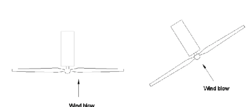
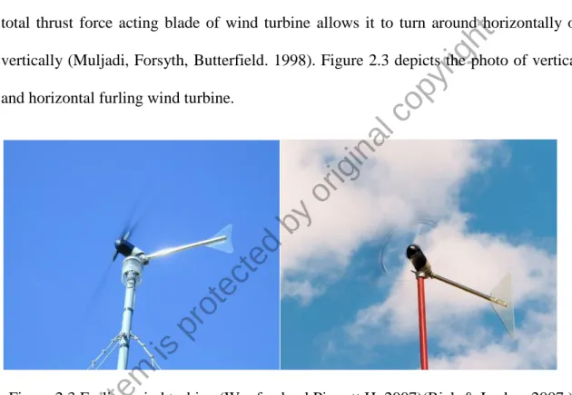
11 2.5 Furling mechanism
The furling mechanism is similar to the passive yaw mechanism, but it's main purposes is for over speed protection. It is designed to have offset angle between tail fin to keep it balance during normal operation. The principle of furling mechanism involves with thrust force acting on the blade of the wind turbine. During high wind speed, the total thrust force acting blade of wind turbine allows it to turn around horizontally or vertically (Muljadi, Forsyth, Butterfield. 1998). Figure 2.3 depicts the photo of vertical and horizontal furling wind turbine.
Figure 2.3 Furling wind turbine (Woofenden l Piggott H, 2007)(Rick & Jordan, 2007.)
© Thi
s i tem
is pr ot ec ted by
or igi nal
c opy
right
12 2.6 Dynamic braking
Dynamic braking is a method of small wind turbine control that involves short- circuiting the generator stator windings. A short-circuit results in large back-torque whose magnitude depends on rotation speed and configuration of the generator; radial or axial flux designs. The acceleration of the wind turbine rotor depends on the net torque:
a net positive torque will cause the rotor to accelerate; while a net negative torque will result in deceleration.
The problem for high wind speed, the magnitude of the rotor torque often exceeding back-torque. In certain circumstance, it is impossible for dynamic braking to make wind turbine decelerate (McMahon, Burton, & Sharman, 2015). On positive side, dynamic braking is possible without involving mechanical brake. This is an advantage for micro- wind turbine since installing mechanical brake is not a feasible solution.
The dynamic series resistor configuration has been proposed for over current protection (Saini, 2013). However, to limit the rotational speed of rotor the dynamic resistor with DC generator must be in parallel connection.
© Thi
s i tem
is pr ot ec ted by
or igi nal
c opy
right