You may not use or facilitate the use of this document in connection with any infringement or other legal analysis regarding Intel products described herein. You agree to grant Intel a non-exclusive, royalty-free license to any patent claim subsequently drafted that includes subject matter disclosed herein. No license (express or implied, by estoppel or otherwise) to any intellectual property rights is granted by this document.
Copies of documents that have an order number and are referenced in this document may be obtained by calling or visiting www.intel.com/design/literature.htm.
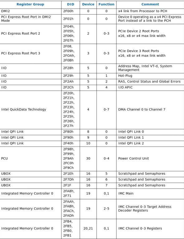
1 Registers Overview and Configuration Process
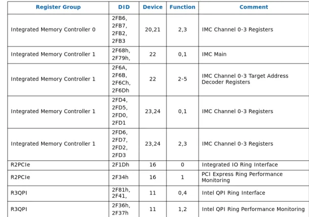
- Platform Configuration Structure
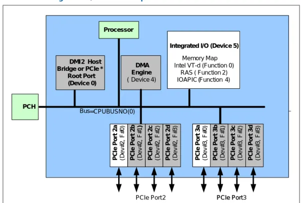
- Processor IIO Devices (CPUBUSNO (0))
- Host Bridge or PCIe *
- Processor Uncore Devices (CPUBUSNO (1))
- Device 19 - 21)
- Device 9)
- Configuration Register Rules
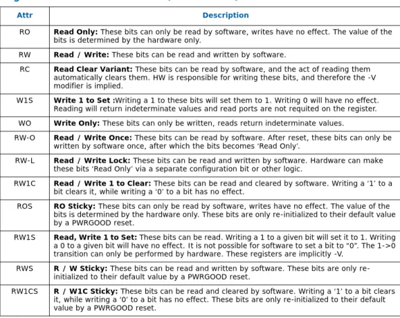
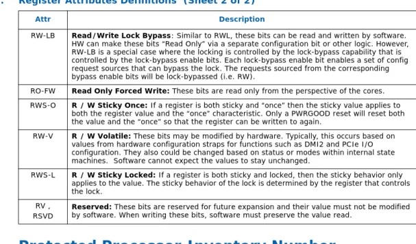
- Register Terminology
- Protected Processor Inventory Number
RO Read Only: These parts can only be read by software, writes have no effect. After reset, these bits can be written by software only once, after which the bits become Read Only. ROS RO Sticky: These parts can only be read by software, writing has no effect.
RW-LB Read/Write Lock Bypass: Similar to RWL, these bits can be read and written by software.
2 Integrated Memory Controller (iMC) Configuration Registers
Device 19,22 Function 0
- pxpcap
- mcmtr
- tadwayness_[0:11]
- mc_init_state_g
- rcomp_timer
- mh_maincntl
- mh_sense_500ns_cfg
- mh_dtycyc_min_asrt_cntr_[0:1]
- mh_io_500ns_cntr
- mh_chn_astn
- mh_temp_stat
- mh_ext_stat
- smb_stat_[0:1]
- smbcmd_[0:1]
- smbcntl_[0:1]
- smb_tsod_poll_rate_cntr_[0:1]
- smb_period_cfg
- smb_period_cntr
- smb_tsod_poll_rate
This bit is set by the iMC when an SMBus Write command is completed on the SMBus. This bit is set by the iMC if an SMBus transaction (including a TSOD invocation or message channel initiated by an SMBus access) that does not complete. This bit is set by the iMC while an SMBus/I2C command is executing (including a TSOD command issued by the IMC hardware).
Note: the '-V' in the attribute implies that the hardware will reset this bit when the SMBus command is started.
Device 19,22 Function 1
- pxpcap
- spareaddresslo
- sparectl
- ssrstatus
- scrubaddresslo
- scrubaddresshi
- scrubctl
- spareinterval
- rasenables
- smisparectl
- leaky_bucket_cfg
- leaky_bucket_cntr_lo
- leaky_bucket_cntr_hi
Note: Just before MC releases the HA block prior to the completion of the spare operation, iMC logic will automatically update the corresponding RIR_RNK_TGT target to reflect new DST_RANK. This register pair contains part of the address of the last patrol scrub request issued. When stop_on_cmpl is enabled, patrol will stop at the end of the address range and set this bit.
The upper 42-bit of the 53-bit counter is recorded in the LEAKY_BUCKET_CNTR_LO and LEAKY_BUCKET_CNTR_HI registers.
Device 19,22 Functions 2,3,4,5
- pxpcap
- dimmmtr_[0:2]
- pxpenhcap
Note: This capability structure is not compatible with versions beyond 1.0 as they require additional capability registers to be reserved. Minimizing the size of this structure is achieved by reporting version 1.0 compatibility and reporting that this is an integrated root port device. When set, parity calculation will enable the inclusion of address bits 17:16 which are sent on chip select lines 7:6 and 3:2.
When set, the High Density Reduced Load mode is enabled, which sends row address bits 17:16 on chip select lines 7:6 and 3:2.
Device 20,21,23,24 Functions 0, 1
- pxpcap
- chn_temp_cfg
- chn_temp_stat
- dimm_temp_oem_[0:2]
- dimm_temp_th_[0:2]
- dimm_temp_thrt_lmt_[0:2]
- dimm_temp_ev_ofst_[0:2]
- dimmtempstat_[0:2]
- thrt_pwr_dimm_[0:2]
This value is subtracted from TEMPOEMHI to determine the point at which the asserted state for this threshold will clear. This value is added to TEMPOEMLO to determine the point at which the asserted state for this threshold will clear. Upper Threshold Value - The TCase threshold at which a system interrupt (SMI or MEMHOT#) is triggered at rate +.
Lower Threshold - TCase threshold at which a system interrupt (SMI or MEMHOT#) is triggered at current rate.
Device 20,21,23,24 Functions 2, 3
- correrrcnt_0
- correrrcnt_1
- correrrcnt_2
- correrrcnt_3
- correrrthrshld_0
- correrrthrshld_1
- correrrthrshld_2
- correrrthrshld_3
- correrrorstatus
- leaky_bkt_2nd_cntr_reg
- devtag_cntl_[0:7]
The error-fixed threshold for this rank that will be compared to the error-fixed-per-rank counter. The SMM software must identify which channel should be flagged for this ranking and set only the valid bit for the channel in the channel pair. If rank sparing is enabled, it is recommended to prioritize rank sparing before initiating device tagging, as the nature of device tagging would render it uncorrectable and any subsequent ECC error from that rank would result in a fatal error.
SMM software must identify which channel should be tagged for this rank and set only the corresponding DEVTAG_CNTL_x.EN bit for the channel containing the failed device.
3 Intel® QuickPath Interconnect (Intel® QPI) Agent Registers
Device 8,9,10 Function 0
- QPIMISCSTAT: Intel QPI Misc Status
It is shared between Intel QPI 0 and Intel QPI 1 in device 8, and Intel QPI 2 value is stored in device 10.
4 Processor Utility Box (UBOX) Registers
Device 16 Function 5
- CPUNODEID
- IntControl
- GIDNIDMAP
- UBOXErrSts
1 : IA32 Logical Flat or Cluster Mode bit can be written by SW, values written by xTPR update are ignored. To override the IA-32 Logical Flat or Cluster Mode value once, return this bit to its default state after the bit is changed. Sets the BIOS to indicate whether the operating system is running logical plane mode or logical cluster mode.
001: Redirect last - last vector selected (only applicable in extended mode) 010 : Hash Vector - selects the first enabled APIC in round-robin fashion from the hash of the vector number. This is error status register in the UBOX and covers most of the interrupt related errors.
Device 16 Function 7
- CPUBUSNO
- SMICtrl
Disable SMI generation for lock timeout, cfg write access to misalignment, and cfg read access to misalignment. This is the enable bit that allows generation of SMI due to a UMC 1 - Generate SMI after the threshold counter has expired. This is the countdown that takes place in the hardware before an SMI is generated due to a UMC.
5 Power Controller Unit (PCU) Registers
- Device 30 Function 0
- MEM_TRML_TEMPERATURE_REPORT
- MEM_ACCUMULATED_BW_CH_[0:3]
- PACKAGE_POWER_SKU
- PACKAGE_POWER_SKU_UNIT
- PACKAGE_ENERGY_STATUS
- Package_Temperature
- TEMPERATURE_TARGET
- Device 30 Function 1
- SSKPD
- CSR_DESIRED_CORES
- Device 30 Function 2
- PACKAGE_RAPL_PERF_STATUS
- DRAM_POWER_INFO
- DRAM_ENERGY_STATUS
- DRAM_ENERGY_STATUS_CH[0:3]
- DRAM_RAPL_PERF_STATUS
- MCA_ERR_SRC_LOG
- THERMTRIP_CONFIG
- Device 30 Function 3
- CAP_HDR
- CAPID0
- CAPID1
- CAPID2
- CAPID3
- CAPID4
- CAPID5
- CAPID6
- SMT_CONTROL
- RESOLVED_CORES
This register contains a metric proportional to the weighted DRAM BW for the channel, including all ranks. Note that this register should not be programmed to a value higher than the value of the cores that the product has. This register is used to configure whether the Thermtrip signal carries only CPU shutdown information or also carries Mem shutdown information.
The register will be used by the HW to enable the ORing of the memtrip information in the thermtrip OR tree. It is or(bit22, bit21); acts as a valid bit for the other two packet conditions. This field has the value 0001b to identify the first revision of the CAPID registry definition.
In the event of an unrecoverable error in one of the copies, the system can obtain a mirror copy of the data. Using memory mirroring means that only half of the installed memory is available to the operating system. This field controls which values can be written to the Memory Frequency Select 6:4 field of the Clocking Configuration registers.
Do not allow the IA32_PERF_CTL register to be written to change ratios. 17:0 RO_V 0x0 CORE_MASK — The resolved IA core mask contains the functional (enabled in SKU) and non-defective IA cores.
6 Integrated I/O (IIO) Configuration Registers
Registers Overview
- Configuration Registers (CSR)
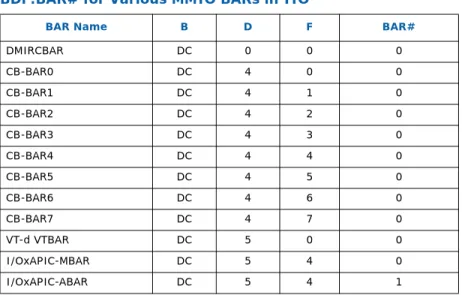
- BDF:BAR# for Various MMIO BARs in IIO
- Unimplemented Devices/Functions and Registers
- PCI Vs. PCIe Device / Function
If the IIO module receives a configuration access over message channel or directly via the JTAG miniport, to a device/function or BAR# that does not exist in the IIO module, the IIO module will stop this access. PCI devices/functions do NOT have a PCIe capability register set and do not decode offsets 100h and beyond. All other functions in the IIO module are PCIe functions and these have a PCIe capability register set and also decode address offsets 100h and beyond.
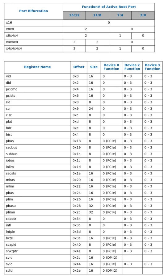
Function 0 PCIe Mode - Port 0 (X4) Device 2 - Port 2 (X16)
Port 3 (X16)
- pcicmd
- pcists
- clsr
- plat
- bist
- pbus
- secbus
- subbus
- iobas
- iolim
- secsts
- mbas
- mlim
- pbas
- plim
- pbasu
- plimu
- capptr
- intl
- intpin
- bctrl
- scapid
- snxtptr
- svid
- sdid
- dmircbar
- msicapid
- msinxtptr
- msimsgctl
- msgadr
- msgdat
- msimsk
- msipending
- pxpcapid
- pxpnxtptr
- pxpcap
- devcap
- devctrl
- devsts
- lnkcap
- lnkcon
- lnksts
- sltcap
- sltcon
- sltsts
- rootcon
- rootcap
- rootsts
- devcap2
- devctrl2
- lnkcap2
- lnkcon2
- lnksts2
- pmcap
- pmcsr
- xpreut_hdr_ext
- xpreut_hdr_cap
- xpreut_hdr_lef
- acscaphdr
- acscap
- acsctrl
- apicbase
- apiclimit
- vsecphdr
- vshdr
- errcaphdr
- uncerrsts
- uncerrmsk
- uncerrsev
- corerrsts
- corerrmsk
- errcap
- hdrlog[0:3]
- rperrcmd
- rperrsts
- errsid
- perfctrlsts_0
- perfctrlsts_1
- miscctrlsts_0
- miscctrlsts_1
- pcie_iou_bif_ctrl
- dmictrl
- dmists
- ERRINJCAP
- ERRINJHDR
- ERRINJCON
- ctoctrl
- xpcorerrsts
- xpcorerrmsk
- xpuncerrsts
- xpuncerrmsk
- xpuncerrsev
- xpuncerrptr
- uncedmask
This bit does not affect the processor's ability to route interrupt messages received on the PCI Express port. The setting of this bit is independent of the Parity Error Response bit (PERRE) in the PCICMD register. This bit is also set (when the SERR enable bit is set) when a FATAL/NON-FATAL message is forwarded to the IIO core error logic.
This bit is set when a root port signals a complete abort status on the primary side (uncore's internal bus). This bit is set by the root port when it receives a poisoned TLP in the PCI Express port. This bit is set regardless of the state of the Parity Error Response Enable bit in the Bridge Control register.
This bit is set when the root port sends a completion packet with a status of 'Completer Abort' (including peer completions forwarded from one port to another). This bit controls the forwarding of ERR_COR, ERR_NONFATAL, and ERR_FATAL messages from the PCI Express port to the primary side. This bit indicates that the root or DMI port has detected a fatal (unrecoverable) error.
When this bit is a 1, a previously configured link reverts to the "disabled" state as defined in the PCI Express Base Specification, Revision 2.0. This bit is set (if not already set) when the status of the Data Link Layer Link Active bit changes in the Link Status register. This bit is set by IIO when a power failure is detected by the power controller (which is reported via the VPP bitstream).
This bit is set by hardware to require that the link equalization process be performed on the link.
6.2.100 coredmask
6.2.101 rpedmask
6.2.102 xpuncedmask
6.2.103 xpcoredmask
6.2.104 xpglberrsts
6.2.105 xpglberrptr
6.2.106 pxp2cap
6.2.107 lnkcon3
6.2.108 lnerrsts
For a downstream component, this field reflects the latest receiver preset value requested from the upstream component on lane 0. For a downstream component, this field reflects the latest transmitter preset requested from the upstream component on lane 0.
- Device 0 Function 0 Region DMIRCBAR
- dmivc0rcap
- dmivc0rctl
- dmivc0rsts
- dmivc1rcap
- dmivc1rctl
- dmivc1rsts
- dmivcprcap
- dmivcprctl
- dmivcprsts
- dmivcmrcap
- dmivcmrctl
- dmivimrsts
- dmivc1cdtthrottle
- dmivcpcdtthrottle
- dmivcmcdtthrottle
- Device 4 Function 0-7
- pcicmd
- pcists
- clsr
- cb_bar
- svid
- sdid
- capptr
- intl
- intpin
- devcfg
- msixcapid
- msixnxtptr
- msixmsgctl
- tableoff_bir
- pbaoff_bir
- capid
- nextptr
- expcap
- devcap
- devcon
- devsts
- devcap2
- devcon2
- pmcap
- pmcsr
- dmauncerrsts
- dmauncerrmsk
- dmauncerrsev
- dmauncerrptr
- dmaglberrptr
- chanerr_int
- chanerrmsk_int
- chanerrsev_int
- chanerrptr
- chancnt
- xfercap
- genctrl
- intrctrl
- attnstatus
The DMA channel sets this bit indicating that the current transfer has an illegal length field value. The DMA channel sets this bit indicating that the current transfer has an illegal control field value. The DMA channel sets this bit indicating that the current transfer encountered an error while writing the destination data.
The DMA channel sets this bit to indicate that the current transfer encountered an error while accessing the source data. The DMA channel sets this bit to indicate that the current transfer encountered an unrecoverable ECC/parity error reported by the DMA mechanism. The DMA channel sets this bit to indicate that the current transfer encountered a parity error.
The DMA channel sets this bit, indicating that the CHAINADDR register has an illegal address, including an alignment error (not on a 64-byte boundary). The DMA channel sets this bit, indicating that the current transfer encountered an error (not otherwise covered under other error bits) when reading or executing a DMA descriptor. The DMA channel sets this bit, indicating that the current descriptor has an illegal following descriptor address, including an alignment error (not on a 64-byte boundary).
The DMA channel sets this bit indicating that the current descriptor has an illegal destination address. The DMA channel sets this bit indicating that the current descriptor has an illegal source address.