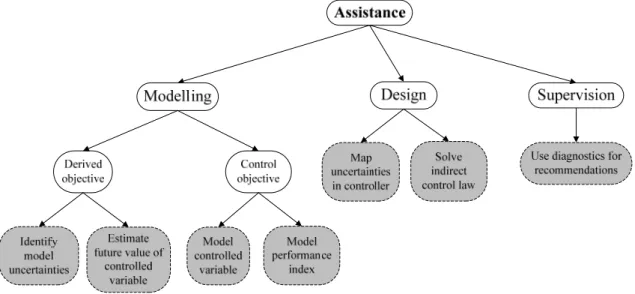
Introduction
The basics of an AMB system
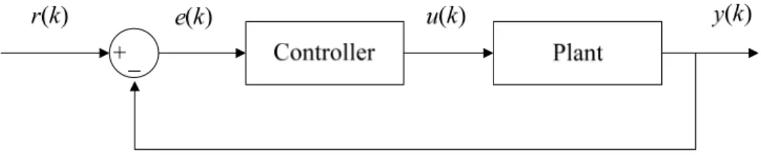
Before anything can be said about these challenges, it is important to understand the basic components and operation of a typical AMB system. There is no contact between rotor and bearing because the rotor is suspended by magnetic forces.
The challenges regarding AMB systems
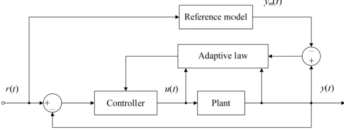
Adaptive control
Artificial neural networks
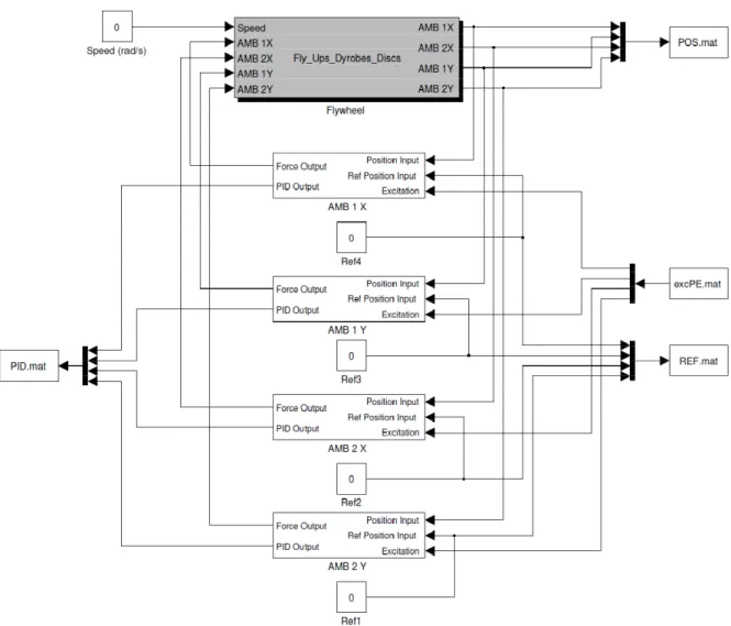
AMB flywheel system
Research problem
Issues to be addressed and methodology
- Adaptive control design
- System identification
- Modelling using neural networks
- Online training
- Implementation
- Performance verification
Therefore, SIMULINK® will be used to develop the simulation model of the adaptive control system. The stability and robustness of the original decentralized PD control system and the adaptive control system will be determined.
Dissertation overview
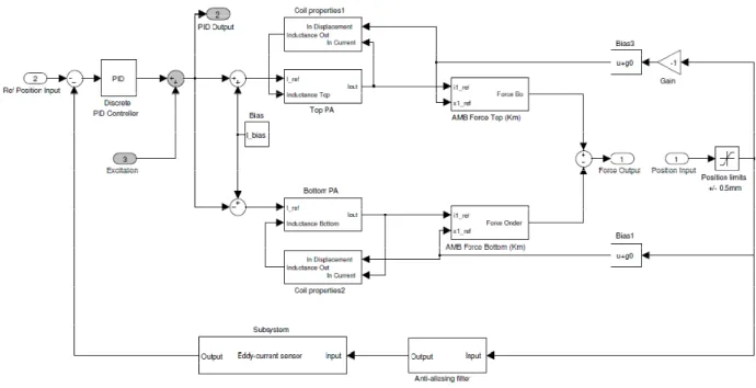
The excitation signal will be injected at point 2 as it is closer to the component of interest - the plant [73]. Something different happens when reinforcement learning is used - the weights are adjusted according to the reinforcement signal [8].
Literature overview
AMB control systems
- Introduction
- Characteristics of AMB systems
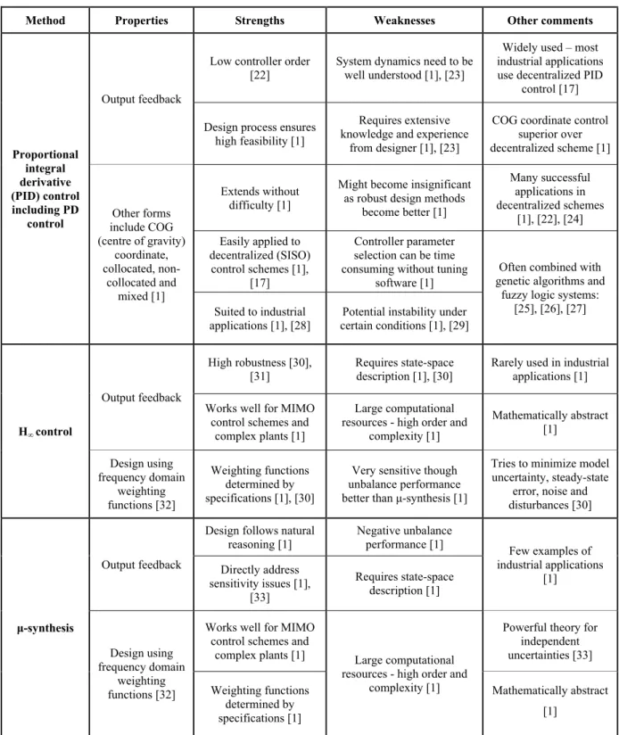
- Advantages of AMBs
- Shortcomings of AMBs
- Applications of AMBs
- Flywheel energy storage systems
- AMB control methods
Saturation and hysteresis in the ferromagnetic material of the magnets also contribute to the nonlinearity of the AMB. According to (2.3), the ability of the flywheel to store energy can be improved by increasing the moment of inertia or rotating the flywheel at higher speeds.
Adaptive control
- Introduction
- Adaptive control design methods
- Adaptive control versus fixed control
- System identification
- Neural networks as model set
In a direct adaptive control (DAC) design, the controller's parameters are updated directly from the adaptive law. In an indirect adaptive control (IAC) design, the controller parameters are calculated from model approximations.
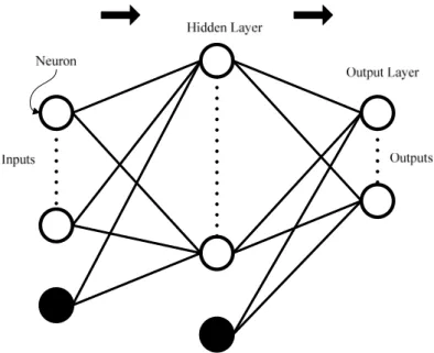
Neural networks
- Introduction
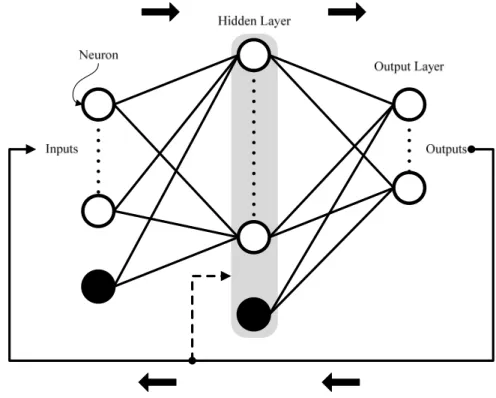
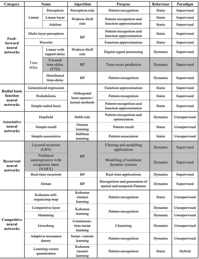
- Neural network architectures
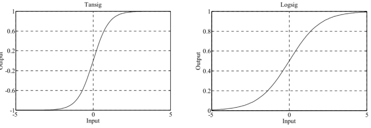
- Activation functions
- Training neural networks
- Training and testing strategy
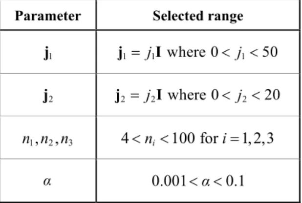
- Parameter selection
- Error function
- Neural network control
Supervised learning – the network is provided with example patterns of correct behavior in the form of input-output pairs and learns to reproduce the relationships found in the data. Unsupervised learning – the desired outputs are not available during training and the network learns through self-organizing behavior using competitive learning rules or a predefined cost function.
Critical overview and conclusions
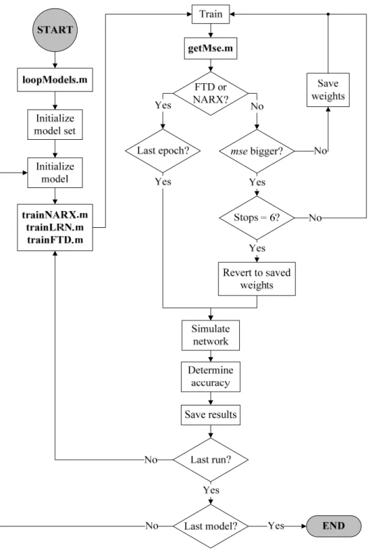
The steps outlined in the system identification loop as applied to the modeling of the AMB flywheel system will now be explained. The inherent instability of the AMB flywheel system did not pose a problem for the NARX architecture. The NARX architecture will be used in the following chapters as an online observer for the construction of the AMB flywheel system [8].
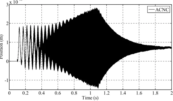
The response of the original system and ACNC with n = 6 can be seen in Figure 5-9.
Architecture selection
Introduction
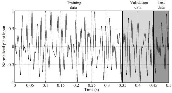
The objective of the offline system identification experiment is to obtain a black box model9 of the plant section10 of the AMB flywheel system. This new model should be able to replace the actual plant in the original control system without causing significant changes in the behavior of the overall system. The AMB system is considered in discrete time because samples of data are used to perform the offline system identification.
The plant has all the characteristics of an AMB system described in the previous sections: dynamic, nonlinear, multivariable and unstable.
Architecture features comparison
Neural network architectures capable of exhibiting the same characteristics need to be identified. The number of possible architectures for system identification is significantly reduced by noting that only certain architectures allow dynamic behavior. Any architecture in Table 2-2 that does not allow system identification of a nonlinear dynamic system is eliminated as shown in Table 3-1.
The choice of the most suitable architecture is now reduced to a performance comparison between the FTD, LRN and NARX architectures.
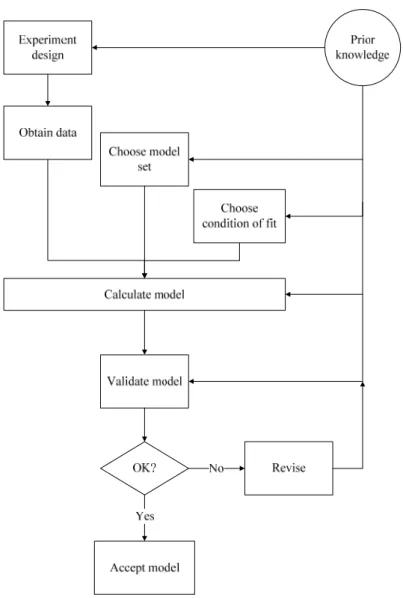
System identification
- Prior knowledge
- Experiment design
- Obtaining data
- Choosing a model set
- Choosing a condition of fit
- Calculating the model
- Model validation
- Model revision
- Implementation
- Results
The range of the second row is extended resulting in the third row of grids. The accuracy of a neural network is the probability of the network to produce grouped estimates, i.e. the system step response using the FTD network as the plant versus the initial system step response can be seen in Figure 3-36.
Note that the response for the system containing the FTD network is significantly different from the response of the original system. The step response of the system containing the NARX network as the plant will now be considered. The frequency response of the NARX system for AMB 1 (x) and the frequency response of the original system for AMB 1 (x) are clearly similar.
Conclusions
The steps of the system identification loop were also identified in the application of the chosen adaptive control design. The next chapter consists of the implementation of the observer-based ACNC in the AMB flywheel system and its performance verification. The position output for AMB 1(y) of the decentralized PD control system can be seen in figure 5-16.
This chapter presented the implementation and simulation results of the observer-based ACNC applied to the AMB flywheel system.
Adaptive control design
Introduction
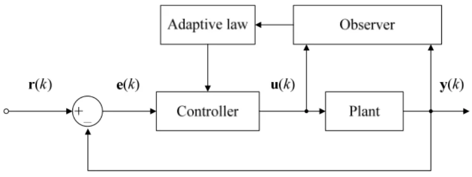
The first step is to identify the nonlinear, dynamic, multivariable and inherently unstable device of the AMB flywheel system online. The output y(k) can be a function of the system states or have a special form as given in (4.2) [8]. Equation (4.5) is the appropriate system description of the device of the AMB flywheel system and will be used for the presentation in the rest of this chapter [8].
For this principle to be effective, parameter approximations must satisfy the following: small estimation errors, bounded parameter estimates, and slow parameter variations [52].
Indirect adaptive control
- Using neural networks
- Reinforcement learning
The key lies in combining (4.5) with a NARX neural network and using it in an indirect adaptive control system. The NARX architecture is most suitable for modeling the AMB flywheel system plant and will be used as an online observer. The controller structure is also chosen as a neural network because this study's goal is to incorporate neural networks into an adaptive controller for the AMB flywheel system.
During supervised learning with a neural network as computational means, the weights are adjusted in relation to the output errors of the neurons.
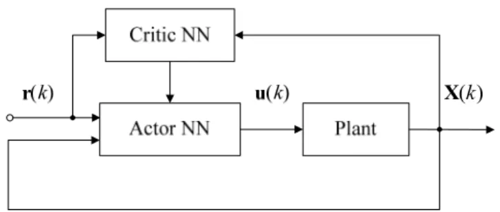
Adaptive critic model
- Lyapunov stability analysis methods
- Observer design
- Actor design
- Critic design
- Observer-based ACNC
- Adaptive laws
It uses an adaptive critic model and a neural network as an online state observer. The selected design uses Lyapunov stability analysis methods to prove the closed-loop stability of the controller. The purpose of this section is to combine (4.5) with the NARX neural network and design an online observer for the revolution of the AMB flywheel system.
It is clearly seen that the current value of the output depends only on the current values of the inputs.
Derivative-free optimization
- Genetic algorithms
- Optimization process
- Initialization and selection
- Crossover and mutation
Each individual or chromosome in the population is just one value or set of values for the parameter or parameters to be optimized. The chromosomes of the current generation with the best fitness values are used as parents in the next generation to produce new offspring or children. Before the initial population is generated, the points in the parameter space must be transformed into the shape of chromosomes ie.
The parents with the best fitness values are selected to ensure that as the population evolves, chromosomes with above average fitness will survive.
System identification loop
A certain number of the best chromosomes from the current generation remain unchanged in the next generation. Crossover ensures that these children will have the best genes from the previous generation and in turn exploits the potential of the current population. Sometimes a population does not contain the necessary information to produce an acceptable solution, no matter how extensively genes are combined and recombined.
The possibility of major mutations is kept small to ensure that good chromosomes from the crossover step are not lost [80].
Performance verification
- Step response
- Robustness analysis
- Stability analysis
The settling time is defined as the time it takes for the system to settle within 2% of the final value. Evaluation of the step response and sensitivity function ensures that both time and frequency domain analysis are performed. The stability of each operating system will be evaluated by calculating the gain and phase margin of the system.
This frequency is simply the minimum frequency where the phase of the loop transfer function L(s) is 180° (or -180°).
Conclusions
Analysis of the results of the step response would clearly show that the ACNC does not comply with the original decentralized PD control system. This is clearly visible in Figure 5-13 as the sensitivity function of the adaptive control system never goes beyond area A (higher than 8 dB). The step response of the adaptive control system was clearly not as good as the step response of the decentralized DP control system.
The evaluation of the sensitivity function of each control system verifies that the adaptive control system is more robust to external disturbances than the decentralized PD control system.
Simulation results
Implementation
- Optimization using genetic algorithms
- Initialization of network weights
The observer's estimation error, x1( ),k is used in the genetic algorithm as the function to be minimized. The difference between the observer in this chapter and the observer in the offline system identification experiment in the previous chapter can be seen in the network parameters. The design parameters for the online observer in this chapter are optimized offline, but the network weights are always re-initialized and continuously trained when used in the closed-loop system.
According to the design in Jagannathan [8], all output layer weights are initialized to zero and trained online.
Observer verification
It is believed that the observer error can be made arbitrarily small by randomly initializing the hidden layer weights and choosing n1 sufficiently large [8]. Remember that the order used by the observer is the same as the order used by the controller. Consequently, the order of the observer had to be increased until the corresponding controller could provide feedback stabilization.
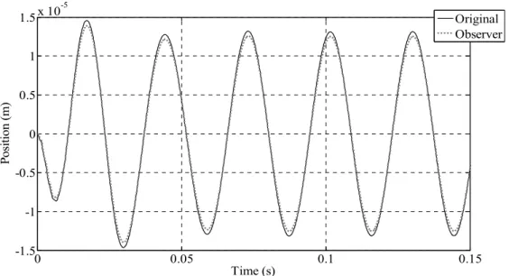
A simulation of the observer in a closed loop configuration without PE at the current maximum rotor speed of 8,300 rpm (133 Hz) is shown in Figure 5-8.
Adaptive controller verification
- Step response
- Robustness analysis
- Stability analysis
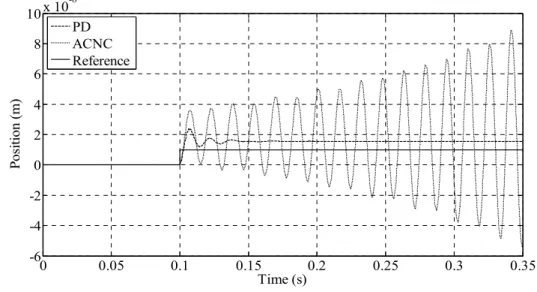
The adaptive controller with n = 12 is compared with the original decentralized PD control system in Figure 5-10. An adaptive control system falls into zone A, while a decentralized PD system falls into zone D. The worst sensitivity of an adaptive control system with a higher chirp disturbance applied to the reference input places the adaptive system in zone D.
The worst gain level achieved by the decentralized PD control system is 9.1 dB and the worst phase margin is 17.7°.
Results assessment
- Step response
- Robustness analysis
- Stability analysis
- Other comments
In the case of significantly larger disturbances, the adaptive control system proves to be only somewhat robust. The gain and phase reserves achieved by the decentralized PD control system confirm the robustness of the system. Genetic algorithm results clearly show that similar chromosomes did not achieve the same level of performance at each initialization.
The only random factor at play was the initialization of the hidden layer weights for each network.
Conclusions
The set of grid weights for a given chromosome was different each time the chromosome was tested. The important questions addressed in this study are highlighted and the result of the proposed methodologies are discussed. The concluding remarks continue with a discussion of the performance difference between a decentralized PD control system and an adaptive control system.
The chapter concludes with recommendations for future work to improve the adaptive controller as applied to the AMB flywheel system.
Conclusions
The decentralized PD control system clearly couldn't control the chatter and the rotor was deliberated. Compared with the decentralized PD control scheme, the observer-based ACNC had relatively high order. The only AMB flywheel system available at the time of this study was the linear decentralized PD control system.
The observer-based ACNC adapted to external disturbances and allowed for the complex behavior of the AMB flywheel system.
Recommendations for future work
- Eliminate need for state information
- Increase hidden layers
- Higher sampling rate for observer
- Improve network weights initialization
- Enhance use of genetic algorithms
- Proven method to select number of neurons
- Adaptive controller order reduction
Dolinar, "Decentraliseret kontrol for aktive magnetiske lejer," i Power Electronics and Motion Control Conference, Portoroz, 2006, s. Kazerooni, "A mu-synthesis based control for compliant maneuvres," i IEEE International Conference on Systems, Man, and Cybernetics , 1999, s. Lee, "Optimal Fuzzy Control of Radial Active Magnetic Bearing Systems," i IEEE International Symposium on Computational Intelligence in Robotics and Automation, Kobe, Japan, 2003, pp.
Pec, "Implementation of neural network sliding-mode controller for DD robot," in IEEE International Conference on Intelligent Engineering Systems, 1997, pp.