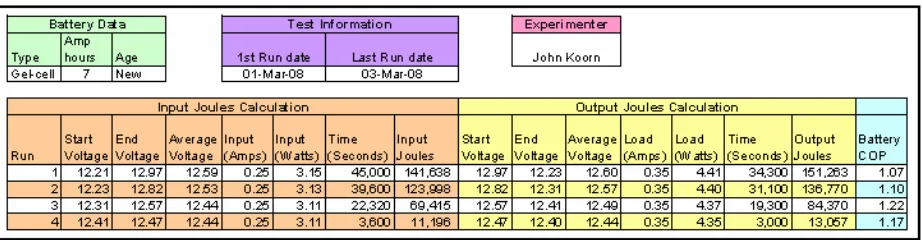
Bedini Monopole 3 Group Experiment
Teks penuh
Gambar
Garis besar
Dokumen terkait
The whole setup consists of a battery, solar panel, low voltage disconnect, charge controller, digital panel display and greenhouse as the load, as shown in Fig.. 7
Ampere hours capacity and energy stored at the battery are considered as the most promising limits in the charging and discharging process in order to keep the life time
a Galvanostatic charge and discharge voltage profiles of the cathode and anode half-cells at a current rate of 0.025 mA/cm2 b Galvanostatic charge and discharge voltage curves of the
Figure 5: Average battery bank SOC and electrical demand for March 2009 Figure 6: Battery bank voltage and current and solar irradiance... 5.2 Electrical performance: supply The
Nomenclature The symbols used in the paper are: 𝑡 Time instant 𝑆𝑜𝐶𝑡 State of Charge at time instant𝑡 𝑄𝑡 Battery capacity at time instant𝑡 𝑄𝑚𝑎𝑥𝑡 Maximum capacity of the battery at
The solar panel must be able to deliver this voltage to the battery after power losses and voltage drop in the cables and charge controller and in conditions in which the solar cells
The results demonstrate that the proposed system is able to control ac-side current, and battery charging and discharging currents at different levels of solar irradiation.. The results
Speed of EPW and tire The amount of input voltage from the battery for driving mode and the plugging voltage during braking can be seen in Figure 12.. In driving mode, to drive an EPW
