The ratio of the width of this sheet strip to the total panel width is known as effective sheet strip ratio. Based on the study of both flat plate structure and plate with column line beams, two empirical equations have been developed to estimate the width of the structurally effective part of the plate. In his parametric study based on finite element analysis, he proposed few empirical equations for determining the effective beam stiffness.
Based on the findings of the experimental results, they proposed a number of constant factors that could be used in their hysteretic model.
RESEARCH SIGNIFICANCE
Second, the equivalent beam approach is used by many researchers as a tool to model and study the behavior of flat slab floor systems. In their research, they used the idealization of a plane frame (Equivalent beam modeling) to analyze the floor system of flat slabs. Luo and Durrani's (1995) equivalent plate method was used to model 2D equivalent frames of flat slab floor systems.
More recently, Kang and Wallace (2005) studied the dynamic response of flat plate systems with shear strengthening.
OBJECTIVES AND SCOPE
METHODOLOGY
ORGANIZATION OF THE THESIS
PLANE FRAME ANALYSIS OF RC FLOOR SYSTEM
Because parameters such as the slab span width ratio, the relative dimension of the column with respect to the longitudinal and transverse spans of the slab can significantly affect the effective slab width (Nilson et. al. 2003).
CONCEPT OF EFFECTIVE SLAB WIDTH
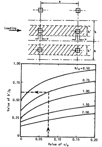
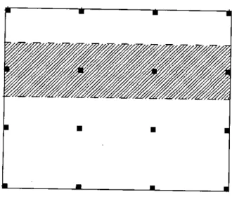
If a rotation e is imposed on the column, the rotation of the plate along the A axis will vary, as shown in Figure 2.1 (b), from e at the column to smaller values away from the column. The equivalent width factor a is obtained from the requirement that the stiffness of the prismatic beam of width al2 must be equal to the stiffness of the plate of width 12 • This equality is obtained if the areas under the two rotation diagrams in Figure 2.1 (b) are equal.
DETERMINATION OF EFFECTIVE SLAB WIDTH
The flexural stiffness of the equivalent beam depends mainly on the width to length of the column spacing and the dimension of the column in the direction of displacement. C, =Size of the support in the transverse direction to the lateral load d=Effective depth of the plate. I, =Length of the space (c/c of the supports) in the direction parallel to the lateral load =6 m I,=Length of the space (c/c of the supports) in the transverse to the lateral load =6 m c, =Size of the support in the direction parallel to Jateralload =0.75 m.
Based on the test results of 40 internal connections, an equivalent beam model is proposed by Luo and Durrani (1995) in which columns are modeled conventionally and the effective slab width is determined as a function of column and slab aspect ratio and magnitude of gravity load.
REMARKS
GENERAL
ASSUMPTIONS
It can be supported by reinforced concrete beam shown in fig. 3.1 known as column line beam structure or directly on columns as shown in fig. 3.2 known as flat plate structure. Eight noded solid element shown in fig. 3.5 is used to model the columns in 3D model. Since comparative behavior of 2D frame with 3D structure is done, any magnitude of lateral force should be OK provided the force is same in both 2D and 3D model.
A complete 3D model has been developed to study the construction behavior of the flat slab system. In the single-frame 3D model, the portion of an interior frame bounded by two adjacent bay centerlines is considered as shown in Figs 3.7 and 3.8. Based on such modeling, the top swing of the single-frame 3D model is compared with the top swing of the full 3D model, and the comparison is shown in Table 3.2 along with the required computational time.
From the above we can see that the single-frame 3D model can complete the analysis in only 11 percent of the time required by the full-frame model while maintaining the acceptable level. Therefore, in this investigation, the single-frame 3D model is used instead of the full 3D model to save valuable time. The theoretical aspect of the equivalence is described in chapter 2 with figure 2.1 where it is shown that the non-uniform curvature of the plate bending in a section of width 12 near the column is equal to the uniform curvature of the equivalent beam width. In reality this equivalence can be obtained from which corresponds to oDD lateral sway model and 2D model.
Currently, the equivalence of the 2D model with the 3D model is determined based on matching the deflection. Therefore, the current study establishes the equivalence of the 2D and 3D models based on top swing matching.
EXAMPLE PROBLEM FOR INVESTIGATION
To determine the effective plate strip ratio for a flat plate based on finite element analysis, the results are shown below with an example. To determine the effective strip ratio of the slab for the column-beam slab shown in Figure 3.15, the previous example is taken with the following additional data. Maximum horizontal deflection for the 3-D model of the sample problem = 0.00875 m Moment of inertia of the 2-D model beam (width 680 mm, depth 600 mm) having the same deflection as the 3-D model.
Maximum horizontal deflection for the 3-D model of the sample problem = 0.02589 m Beamwidth of the 2-D model causing deflection as the 3-D model = 4.24 m.
COMPUTATIONAL INVESTIGATION
GENERAL
DETERMINATION OF EFFECTIVE SLAB STRIP RATIO FOR FLAT PLATE STRUCTURE
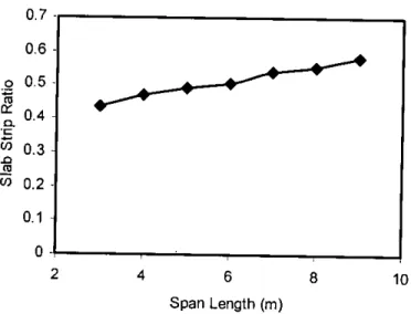
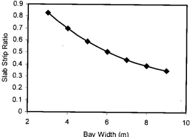
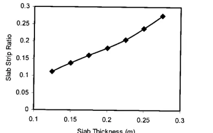
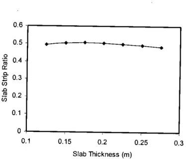
For flat plate structures, the effective plate strip ratios obtained for different plate thicknesses are shown in Fig. For flat slab structures, the effective slab strip ratios obtained for different span lengths are shown in Figs. For flat plate structures, the effective bar ratios obtained for different bay widths are shown in Fig.
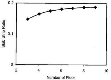
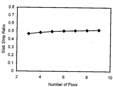
For flat plate structures, the effective plate band ratios obtained for different numbers of spans are shown in fig. For this reason, the number of spans does not show any effect on the effective plate strip ratio (a). For flat plate constructions, the effective plate strip ratios obtained for different story numbers are shown in fig.
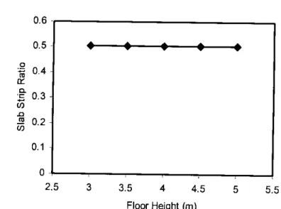
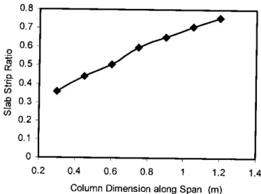
For this reason, the floor number does not show any effect on the effective strip ratio of the panels (a). For flat slab structures, the effective slab strip ratios obtained for different floor heights are shown in Fig. For flat plate structures, the effective plate strip ratios obtained for different column dimensions along the span are shown in Fig.
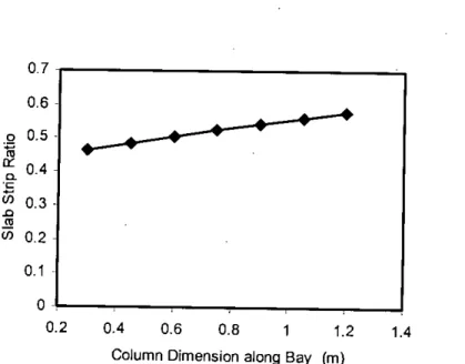
For this reason, the effective plate strip ratio (a) increases with increasing column dimension along the span. For flat plate structures, the effective plate strip ratios obtained for different column dimensions along the bay are shown in Fig.
DETERMINATION OF EFFECTIVE SLAB STRIP RATIO FOR SLAB WITH COLUMN LINE BEAM
For the slab with column line beam structures, the effective slab strip ratios obtained for different slab thicknesses are shown in Fig. line girder structures, effective slab strip ratios obtained for different bay widths are shown in Figs.
For slab with columnar beam structures, the effective slab strip ratios obtained for different numbers of spans are shown in Fig. For slab with column line beam structures, the effective slab strip ratios obtained for different story numbers are shown in Fig. For this reason, the number of floors shows no effect on the effective plate strip ratio (a).
For slabs with column line beam structures, the effective slab strip ratios obtained for different floor heights are shown in Fig. For slab with column line girder structures, the effective slab strip ratios obtained for different column sizes along the span are shown in Fig. in column line beam construction, the effective slab strip ratios obtained for different column sizes along the bay are shown in Fig.
For slabs with column line beam structures, the effective slab strip ratios obtained for different beam widths are shown in Fig. For slab with column line beam structures, the effective slab strip ratios obtained for different beam depths are shown in Fig.
COMPARATIVE STUDY FOR FLAT PLATE STRUCTURE
It can be seen that the trend line below the parameters of the study has an upward slope. For this reason, we observed a slight increase in the effective plate strip ratio (a) with increasing column size along the bay. It can be observed that the trend line under the parameters of the study is almost horizontal.
For this reason, the beam width does not play a significant role in determining the effective strip ratio of the slab (a). It can be seen that the trend line under the parameters of the study is downward sloping. For a flat plate, the effective plate strip ratios obtained for different span lengths are shown in Figure 4.19.
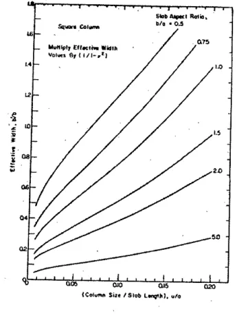
From fig 4.19 it can be observed that Pecknold's values are the highest among all methods which are now followed by Lou and Durrani's method. For flat plate slab, the effective plate strip ratios obtained for different bay widths are shown in fig 4.20. From fig 4.20 it can be observed that Pecknold's values are the highest among all methods which are now followed by Lou and Durrani's method.
For flat plate, the effective plate strip ratios obtained for different column dimensions along the span are shown in Fig. 4.21. From fig. 4.21 it can be observed that Pecknold's values are the highest among all methods closely followed by Lou and Durrani's method.
REMARKS
For column-line-beam slab constructions, the important parameters affecting a are span, beam width, column dimension along span, column dimension along beam, slab thickness, beam width and total beam depth.
34; III
- GENERAL
- EMPIRICAL RELATION FOR FLAT PLATE STRUCTURE
- Normalization
- Verification of the Proposed Empirical Equation
- EMPIRICAL RELATION FOR SLAB WITH COLUMN LINE BEAM
- FINDINGS
- EMPIRICAL RELATION FOR ESTIMAT1NG EFFECTIVE SLAB STRIP RATIO
- SCOPE FOR FUTURE INVESTIGATION
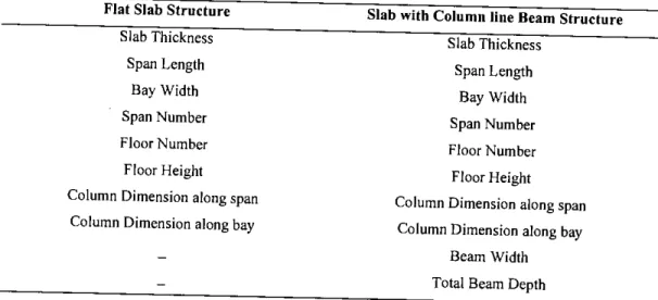
Instead of directly evaluating the effective plate-strip ratio (a) in terms of structural parameters, it would be easier to develop an expression for the effective beam moment of inertia (I). From these figures, the controlling parameters for the effective slab strip ratio are determined for both the Flat Slab Structure and the Column Line Beam Slab. For flat-slab structures, spades with effective ratio of slab strips to span length, bay width, column dimension across span, and column dimension across bay.
The effective slab strip ratio does not change with slab thickness, span number, floor number, and floor height for flat slab structures. For column-line beam-type floor slab, the effective slab-strip ratio varies with slab thickness, span length, bay width, column dimension across span, column dimension across bay, beam width and beam depth. The effective ratio of slab strips does not change with the span number, floor number and floor height for column line beam slab.
Column-line beam structures have reduced the effective plate-strip ratio than flat-plate structures by about 63.33%.