A smart irrigation system is proposed in [2] for saving water in the large field. Moreover, the disadvantage of the system is that it cannot understand the water level, and as a result, water savings are actually not optimized.
Project Planning 13
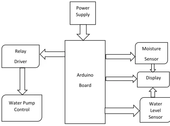
Block Diagram 13
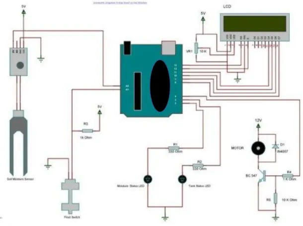
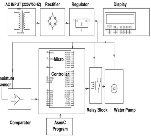
The board can operate on an external supply of 6 to 20 volts. If supplied with less than. Above is the way we are going to implement the hardware circuit. The first part of the block diagram is another sensor and the second part is an LCD panel and motors to supply water.
Schematic Diagram & Working Explanation 15
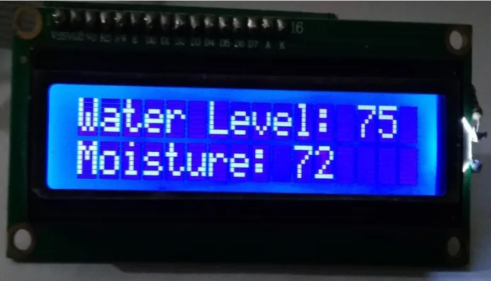
Once the Arduino has decided whether the soil was in a wet or dry state, it will decide to activate the water pump. If the sensor reading indicates that the soil is dry, it will activate a simple DC motor that will pump water into the soil. In this way, soil moisture. In this way, soil moisture will be preserved indefinitely. A little help, here's an unsolvable way to make your own water pump with a simple DC motor. For those who are really concerned about their plants. Here's a feature that might make you happy. When the humidity sensor detects low humidity, the motor turns on and a message appears on the LCD screen.
Description of the Circuit Diagram 16
A moisture sensor is associated with each of the plurality of zones. Each such sensor is periodically interrogated with a pulse signal provided by the microcontroller via a driver or intermediate circuit. This interrogation signal causes the moisture sensors to output an analog voltage that is proportional to the amount of moisture in the soil in which the sensors are embedded. The analog signal is fed to an analog-to-digital converter, which creates a digital representation of the measured analog quality on a data bus leading to the microcontroller. -digital converters suitable for use in the system are ADC 0809(4). It contains a monolithic CMOS device with an 8-bit A/D converter, an 8-channel multiplexer and microcontroller-compatible control logic. Using successive approximation as the conversion technique, this 8-bit A/D converter is seamlessly interfaced to the associated microcontroller with latched and decoded multiplexer address inputs and latched TTL tri-state outputs.
Project Setup 18
- Programming 21
- Power 22
- The power pins are follows 23
- Memory 23
- Arduino Details 27
- Power (USB/Barrel Jack) 27
- Pins 28
- Power LED Indicator 30
- TX RX LEDs 31
- Main IC 32
- Voltage Regulator 33
Arduino needs 5 volts DC and about I amp to operate properly. If it is not charged with adequate power, it may behave strangely or not work at all. With too much power supplied, it can overheat and will be destroyed. Most smartphones, MP3 players and other USB devices require the same 5 volts and I would argue that the Arduino does. A 9-volt battery is optimal for battery-powered Arduino. The Arduino will regulate the 9 volts to 5 volts and work fine. In the case of the thermostat in Figure 2, the power connector is used instead of the USB cable. This is because the program is already saved and running on the Arduino. Optimally, the power connector for this 3 case provides 9 volts from a small transformer connected to a nearby outlet, so that the user does not have to change the batteries. The gate of the transistor is connected to the output of the LMV358 operational amplifier, which is used as a comparator. The comparison is between 3V3 and Vin/2. When Vin/2 is large, it will result in high power from the comparator and the P-channel. Rather than requiring a physical reset button to be pressed before booting, the Arduino/Genuine Nano board is designed to allow a reset via software running on the connected computer. One of the hardware flow control (DTR) lines of the ATmega8U2/16U2 is connected to the reset line of the ATmega328 via a 100 nanofarad capacitor. When this line is asserted (law taken), the reset line goes low long enough to reset the chip. The Arduino software (IDE) uses this capability to allow code to be loaded by simply pressing the load button on the interface toolbar, this means that the bootloader can have a shorter timeout as the DTR decrement can be well timed to start loading.
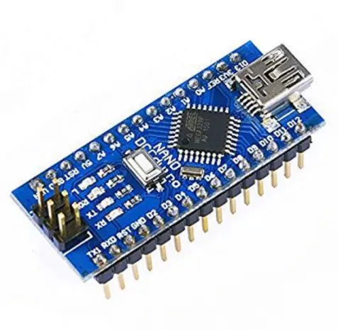
Every Arduino board needs a way to connect to a power source. The Arduino NANO can be powered by a USB cable coming from your computer or a wall adapter (like this one) that terminates in an outlet. The pins on your Arduino are where you connect the wires to build the circuit (probably in conjunction with a table and some wire. They usually have black plastic, headers that allow you to easily connect the wire to the board. The Arduino has several different types of pins, of which each is labeled on the board and used for different functions. The reset button works almost the same as unplugging the board and plugging it back in. It restarts your program from the beginning. The same thing happens when you program the board - the USB interface presses the reset button instead of you. This then goes into the bootloader for a second or two to try and program it. When you reset the board, the LED on pin 13 should flash something .
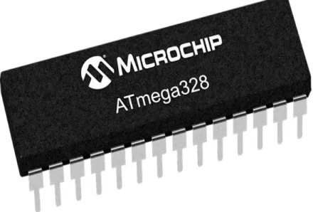
The black thing with all the metal legs is an IC, or Intergrated Circuit (13). Think of it as the brains of our Arduino. The main IC on the Arduino varies slightly from board type to board type, but is usually from the ATmega series of ICs from the ATMEL company. This can be important as you may need to know the IC type (along with your board type) before uploading a new program from the Arduino software. This can usually be found in writing on the top of the IC. Most of the projects I do are based on 5V voltage supply, and making the voltage supply regular requires a voltage regulator. The most commonly used voltage regulator is a 7805 IC that operates at 1A. In this instructable I'm going to show you how to build a 5V voltage regulator, it can be used to power an atmega328 if you're replicating an Arduino or building a portable power supply. The voltage regulator (14) is not actually something you can (or should) interact with on the Arduino. But it is potentially useful to know that it is there and what it is for. The voltage regulator does exactly what it says it controls the amount of voltage that is let into the Arduino board. Think of it as a kind of gatekeeper, it will turn away any extra voltage that is let into the Arduino board. Think of it as a kind of gatekeeper, it will turn away an extra voltage it can damage the circuit. Of course, this has its limits, so don't connect your Arduino to anything greater than 20 volts. Like an Arduino uses the same 7805 as the voltage regulator to power an atmega328, or if you happen to burn the Arduino regulator you can buy one from eBay and replace the one on board. This project is also the stater for a virtual USB project.
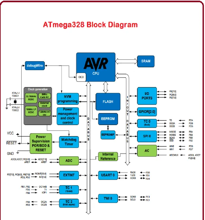
Block Diagram of ATmega328p 37
Water Level Sensor 39
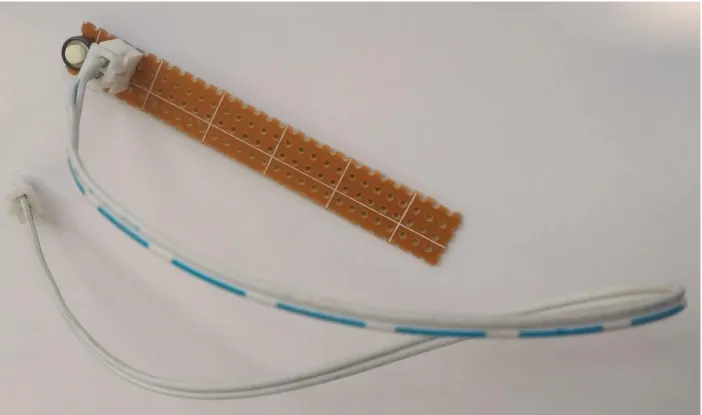
This sensor is a very important part of our project. It takes its input from the ground. If there is less water level in the ground, the sensor will provide an analog input to the ADC inside the MSP430 (ADC explained later in the report). Basically, the water level sensor indicates the water level in the soil. Base level sensors can be used to identify the point at which a liquid drops below a minimum or rises above a maximum level.
Some types use a magnetic float, which rises and falls with the liquid in the container. Once the liquid, and by extension the magnet, reaches a certain level, a reed magnetic switch is activated. The ADC (Analog to Digital Converter) which is one of the most important built-in features of the MSP samples this Analog input value given by the sensor registers (ADC10MEM). The moisture sensor consists of two leads that are used to measure the volume of water content in soil. These leads allow the current to pass through the soil and in return calculate the resistance value to measure the moisture level. If there is more water in the soil, then the soil will conduct more electricity, meaning less resistance value together with high level of moisture. In the same way if there is less water in soil then soil will conduct less electricity, means high resistance value together with low level of moisture. This sensor is one of the main parts of our project. It takes its input from the soil.
If there is less moisture in the soil, the sensor will give an Analogue input to the ADC inside the MSP430 (ADC is explained later in report). Soil moisture sensors measure the volumetric water content in soil. Since the direct gravimetric dielectric constant of a certain volume element around the sensor is obtained by measuring the operating frequency of an oscillation circuit. The ADC (Analog to Digital Converter) which is one of the most important built-in features of the MSP samples this Analog input value given by the sensor registers (ADC10MEM) ).
Water Pump 41
34; Efficient automatic plant irrigation system using ATMEGA microcontroller." International Journal of Emerging Trends in Electrical and Electronics (IJETEE – ISSN Vol 7 (2013). 34; Smart irrigation system." IOSR Journal of Electronics and Communication Engineering (IOSR-JECE) , Volume 10, Issue 3, Ver. 34;An automatic irrigation system using ZigBee in a wireless sensor network." In Pervasive Computing (ICPC), 2015 International Conference on, pp.
34;Smart Garden Watering System Using Wireless Sensor Networks." Engineering and Technology (ICET), 2014 International Conference on. 34;Plant Water Quantity Measurement Using itplanter." In SICE Annual Conference (SICE), 2011 Proceedings of, p. 8] Venkata Naga Rohit Gunturi, ''Micro Controller Based Automatic Plant Irrigation System'', International Journal of Advances in Research & Technology, Volume 2, Issue 4, April-2013.
34;GSM based automatic irrigation control system for efficient use of resources and crop planning using an Android mobile.” IOSR Journal of Mechanical and Civil Engineering (IOSR-JMCE) e-ISSN.