In my capacity as supervisor of the candidate's thesis, I certify that the above statements are true to the best of my knowledge. Rail is the most popular and friendly transport system in most of the world's cities. But at every turn the train faces an unexpected situation while running due to wrong signal, wrong track change, unsafe level crossing etc.
Sonargaon University, who in spite of busy and hectic schedule found time to do my work, constant guidance and giving valuable suggestions in accomplishing the work. I am grateful to those teachers, staff members of the respective workshops and those who helped me directly and indirectly for the realization of the project work. Finally, we would like to thank our parents and family for their support in every aspect of the journey and our respective teachers whose lessons and teachings have guided us along this path.
Some may be the railroad company's fault, while others are because a conductor or railroad employee was negligent.

Mechanical Failure
Speedy Trains
Defective Tracks
7.Derailments
Unprotected railroad crossings
09.Stalled cars on the track
Suicides
Chapter-Two
- Objectives
- Accident Study
- Railway Accidents
- Classification of railway accidents
- Indicative Accidents
- Equipment Failures
- Unusual Incidents
- Train collisions
- Definitions of some related terms
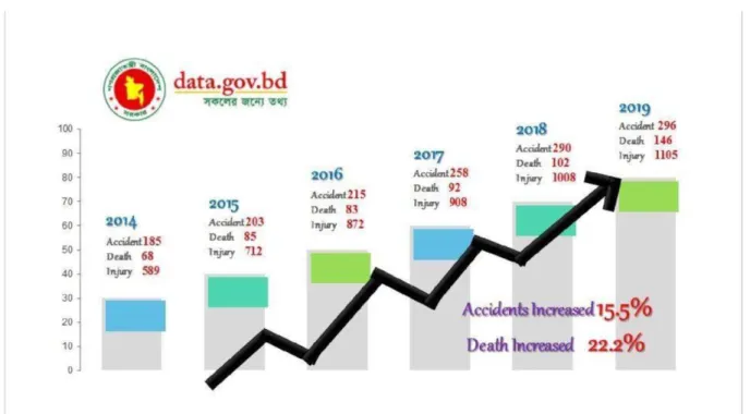
A railway accident is defined as any occurrence affecting or likely to affect the safety of the railway, its engine, rolling stock, permanent way, works, passengers or servants which either causes or may cause delays in trains or losses in railways ( Arora and Saxena, 2006). Subsequent train accidents: Includes railway accidents that have serious consequences in terms of loss of human life, human injury, loss of railway property or disruption of railway traffic. Other railway accidents: All other accidents not covered by the definition of subsequent train accidents should be treated as 'other train accidents'.
In reality it is not about accidents, but about serious potential hazards and includes all instances of passing signals at risk, avoided collisions and violation of blocking rules. Class H - Signal to passing trains in danger Class J - Failure of engine and rolling stock Class K - Failure of permanent connection. Collisions between trains, including a train with passengers, or derailment of a train, or part of a train with passengers.
Damage to track or works from severe flooding that involves disruption of traffic but does not cause a train accident. Cases of running over obstacles on the route, including road vehicles at railway crossings, but which do not cause an accident specified under "Class A". Collisions and derailments not falling under 'Class A' and averted collisions or fires in trains or within railway boundaries.
Train Separation – Breaks of tie rods of couplings which do not cause a train to separate should not be treated and reported as 'Class D' accidents. A rear-end collision is an incident where a train crashes into the train in front of it, usually caused by tailgating or panic steps. If, outside the station boundaries, the distance between the two trains or the train and the obstruction at the time the train or trains finally came to a stop is 400 meters or more.
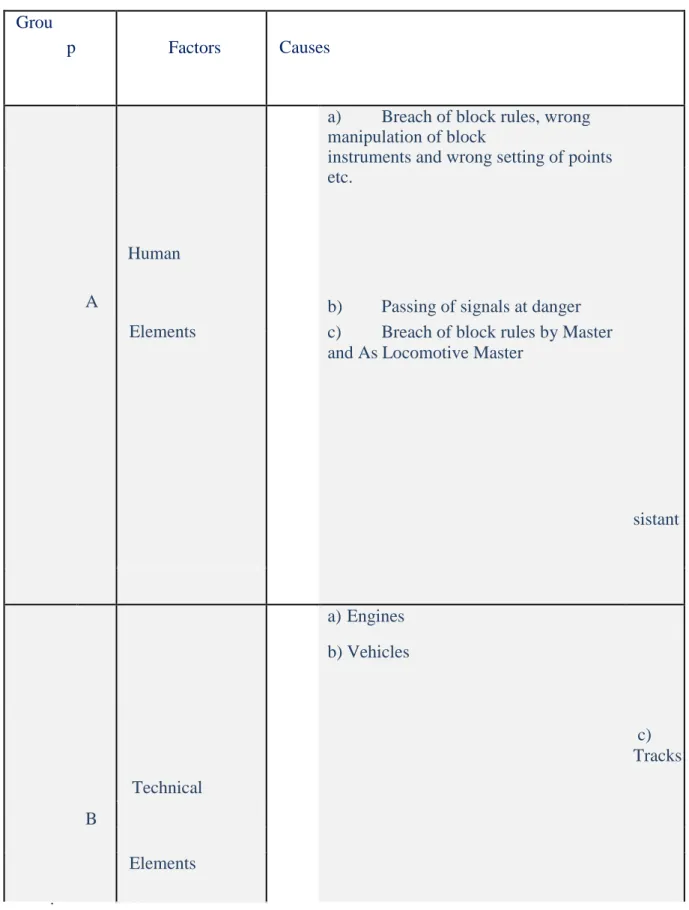
If there is an intermediate stop signal for danger within the limits of the station, which controls a moving train, and the observance of the signal given by the stop signal by the moving train prevents a collision between the two trains or between the train and the obstacle. Bangladesh Railway mentioned several causes of train derailment and classified them into three main elements as shown in Table 2. They provide a continuous and flat surface for the train to move, provide lateral guidance of the train wheels and carry the load of the wheels.
When a train enters a block section without any 'authorisation to proceed' or with an improper authorization to proceed, or is received on a blocked line not implying an averted collision, or when it is on a wrong line from a station or a enters or is received a Catch/Slip siding or sand bump, which is a violation of the block rules.
Chapter Three
- Arduino Uno
- Programming
- Warnings
- Difference with other boards
- Power
- The power pins are as follows
- Memory
- SRAM memory: 2KB volatile memory. This is used for storing variables used by the application while it's running
- EEPROM memory: 1 KB nonvolatile memory. This can be used to store data that must be available even after the board is powered down any then powered up again
- Communication
- Automatic (Software) Reset
- Arduino Details
- Reset Button
- Power LED Indicator
- TX RX LEDs
- Main IC
- Voltage Regulator
After the arduino IDE is installed on the computer, connect the board to the computer with a USB cable. Once the sample code (also shown below) is loaded into your IDE, click the "load" button on the top bar. 5v this pin outputs the associated 5v from the board regulator, it can be powered from the DC power connector (7-12V), the USB connector (5V) or the board VIN (7-12V), powered via pins 5V or 3.3 V bypasses the fegulator and can damage your board, no no advise.
IOREF: This pin on the Arduino/Genuino boards provides the voltage reference when the microcontrollers are operating. A properly configured shield can read the 1OREF pin voltage and select the appropriate power source or enable voltage translators on the output to work with 5V or 3.3V. Arduino/Genuino Uno has a number of facilities to communicate with a computer, another Arduino/Genuino board or other microcontrollers, A T mega328 provides, UART TTL (5v) serial communication which is available on digital pins 0 (RX) and In (TX), an Atmega 16U2 on the board channels this serial communication over USB and appears as a virtual port to software on the computer, the 1602 firmware uses standard USB COM drivers and no external drives are required, although on Windows if file is required. The Arduino Sotware (IDE) includes a serial monitor which allows simple text to be sent to and from the board.
The RX and TX LEDs on the board will flash when data is being transferred via the USB to serial chip and the USB connection to the computer (but not for serial communication on pins 0 and 1). Arduino has several different types of pins, each labeled on the board and used for different functions. GND (3): Short for "Ground" on Arduino, there are several GND pins, any of which you can use to ground your circuit.
Most simple components used with Arduino are happy to run on 5 or 3.3 volts. So they would travel fast and once, at the completion of the initial byte. The main IC in the Arduino is slightly different from the type of board, but it is usually from the Atmega line of TC from the company ATMEL.
This can be important as you may need to know the IC type (along with your board type) before loading a new program from the Arduino software. The voltage regulator (14) is not actually something you can (or should) interact with on the Arduino.
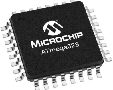
3 .18 Description of ATmega328 Microcontroller
Block Diagram Of ATmega328p
Chapter Four
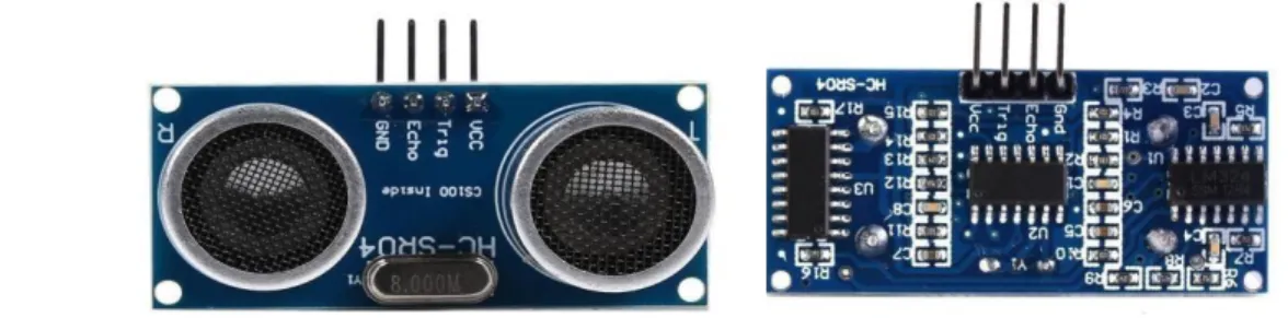
- Ultrasonic Sensor
- History Of Ultrasonic Sensor
- How Ultrasonic Sensors work?
- IR Sensor Module
- Infrared Radiation Theory
- The Types of Infrared Sensors
- The Working Principle of Infrared Sensors
- Power Distributor
- HC-05 Bluetooth Module
- Working Procedure of HC-05 Bluetooth Module
- L298N Motor Controller Module
- How it works
- Pins
- Specifications
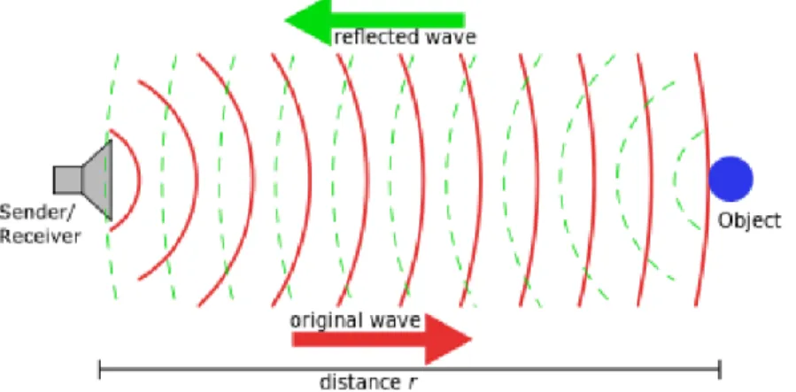
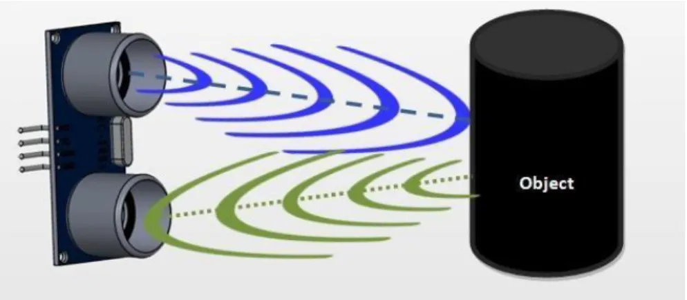
The module has two eyes at the front, which form the ultrasonic transmitter and receiver. The ultrasonic transmitter emits an ultrasonic wave, this wave travels through the air and when it encounters any material, it bounces back towards the sensor. This reflected wave is detected by the ultrasound receiver module as shown in the figure below. The hydrophone could send and receive low frequency sound waves and was later used to detect submarines in WW1.
Subsequently, many scientists such as Ian Donald, Douglas Howry, Joseph Holmes, John Wild and John Reid improved the various aspects of ultrasonic sensors in the medical field which enabled the diagnosis of stomach cancer, ovarian cysts, detection of twin pregnancies, tumors etc. Industry wasted no time jumping on the bandwagon either and soon developed techniques such as ultrasonic welding and non-destructive testing in the early 1960s. Ultrasonic sensors are devices that use electrical-mechanical energy transformation, the mechanical energy is in the form of ultrasonic waves, to measure distance from the sensor to the target object.
When ultrasonic waves impinge on an object, diffuse reflection of the energy occurs over a wide solid angle that can be as high as 180 degrees. So a fraction of the incident energy is reflected back to the transducer in the form of echoes and is detected. Where' is the time taken by the wave to reach back to the sensor and ' ' is the angle between the horizontal and the path taken as shown in the figure.
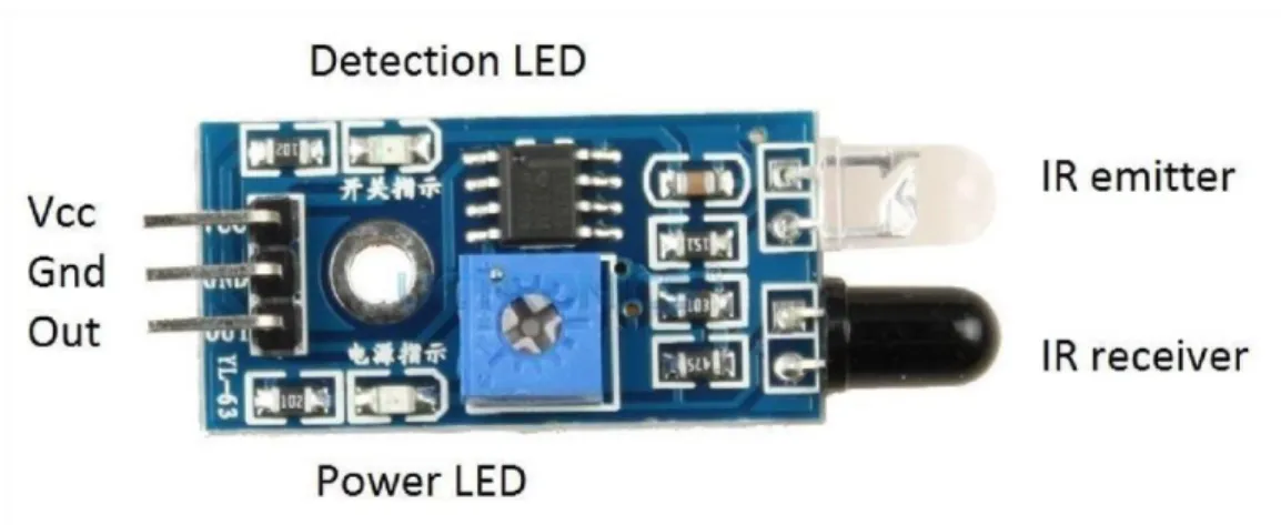
An infrared sensor is an electronic device that emits light to sense some aspect of the environment. The emitter is simply an IR LED (Light Emitting Diode) and the detector is simply an IR photodiode that is sensitive to IR light of the same wavelength as that emitted by the IR LED. When IR light falls on the photodiode, the resistance and output voltages will change in proportion to the magnitude of the IR light received.
In the electromagnetic spectrum, infrared radiation can be found between the visible and microwave ranges. The Android app is designed to send serial data to the Arduino Bluetooth module when you press a button in the app. The Arduino Bluetooth module on the other end receives the data and sends it to the Arduino via the TX pin of the Bluetooth module (connected to the RX pin of the Arduino).
Take the water wheel analogy and think of the water hitting it in pulses but with a constant flow.
Chapter Five
Project Planning
Project Demo Model
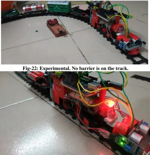
On the other hand, in Figure 23 the train stops after observing an obstacle on the tracks. For power supply we are building a powerful battery with three Ultra Fire batteries which give us 3.7V each. We have developed our traditional railway signaling system, which are manual and completely wireless signaling system.
So when a train breaks the signal, our system will automatically inform the control room by giving a beep and light indicator.
CHAPTER SIX Conclusion
CHAPTER SEVEN Future Recommendation
Railway lines should not be used for various purposes by vendors, street vendors and others. To prevent accidents involving signal neglect or exceedance, automatic warning devices should be introduced.
REFERNCES
12] Shikder, K., 'Intelligent system for train engine with automatic gate control using wireless technology in Bangladesh', Department of EEE, American International University- Bangladesh (AIUB), International Journal of Science and Research (IJSR) , ISSN (Online ):.
Appendix