37 Figure 3.14 Stress-strain diagram for RC rectangular beam design 40 Figure 3.15 Variation of ζ for long-term deflection 43. 78 Figure 4.16 Total deflection of RC and Composite beams 79 Figure 4.17 Instantaneous deflection of RC and Composite beams Figure 4.17 Instantaneous deflection of RC and Composite 48.8. thermal deflection of RC and Composite beams 80 Figure 4.19 Comparison between RC and Partially Restrained Composite.

INTRODUCTION
- Background
- Objectives and Scope of the Study
- Organization of the thesis
- History and Structural Applications
- Types of Composite Slab and Beam
- Strength of Composite Beams
- Percent of Composite Action
- Material Limitations
- Research on Composite Beams and its Components
- Experimental Investigations
- Numerical Investigations
- Summary
Steel and concrete are combined by using break connectors on the top flange of the steel elements. The strength of the shear connectors determines the interaction between the concrete slab and the steel beam.

METHODOLOGY
Introduction
Framing System
- Composite Floor System
- Analysis and Design Conditions for Composite Beam
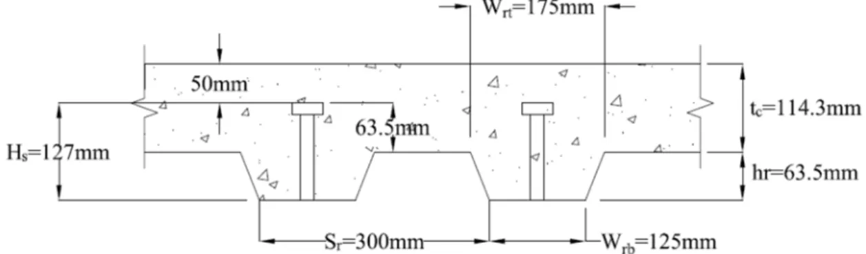
- Selection Criteria of Deck Slab (As per AISC 360-10)
- Flexible Moment Connection
- Moment-Rotation Curve
Finally, the strength and flexural behavior of the composite beam will be compared with an RCC beam of similar span length. Connections at the end of footings under relaxed conditions were considered for analysis. At the end of the beams, the upper beam will be in tension and the lower beam will be in compression.
However, since the positive moment is low, the composite capacity of the beams is not mobilized. Therefore, we can conclude that neither fully fixed nor fully relaxed end connections are perfectly suitable at the end of the beams. When analyzing the structure, it can be assumed that the connection does not allow relative rotation.
The force-deformation response characteristics of the connection must be included in the analysis of the structure. The connection that allows sufficient rotation at the ends of the beams and resists no more than 20 percent of the fixed end moment; There is talk of a simple connection.

Foundation System
Beams will be designed for different spans and the results will be compared with the results obtained from composite beams.
Material Properties
- Composite Structure
Member Stiffness
- Stiffness of RC members
- Stiffness of Composite Beam
- Local Buckling
When the service load moment Ma is about 3 times the cracking moment, the effective moment of inertia is reduced to Icr. Ec is the modulus of elasticity of concrete and Iut is the moment of inertia of the transformed untracked section. According to Section 9.5.2.4 of ACI 318-08, a simple average of the values obtained from Equation 3.4 for the positive and negative moment critical sections can be used to calculate the effective moment of inertia of RC beams.
Iem is the effective moment of inertia for the mid-span and Ie1 and Ie2 are those for the negative moment sections at the end of the beams. When the applied moment is about 2 to 3 times the cracking moment, the effective moment of inertia of RC beams decreases to almost half of the uncracked portion. Itr= moment of inertia for the fully assembled uncracked transformed section; in.4 (mm4) ΣQn= strength of steel anchors between the point of maximum positive moment.
Ipos = Effective moment of inertia for positive moment, in4 (mm4) Ineg = Effective moment of inertia for negative moment, in4 (mm4). The effective moment of inertia is based on the cracked transformed section taking into account the degree of composite action.

Design Loads and load combination
- Fundamental Considerations
- Design Steps of RC Beams
- Deflection Calculation of RC Beam
- Effective Width of Concrete Slab
- Strength of Composite Beams During Construction
- Limitations for Concrete Filled Steel Deck
- Effective Concrete
- Load transfer between the steel beam and concrete slab
- Negative Flexural Strength of Composite Beams
- Design Flexural Strength and Allowable Strength
- Design Steps for Composite Beams
- Deflection of composite beams
The total reinforcement required at the bottom of the beam will be As= As1 + As2. The positive flexural strength of the composite beam can be controlled by the strength of the steel section, concrete slab or steel anchors. Alternatively, the available flexural strength of the composite beam can be calculated from the plastic stress distribution in the composite section.
In this study, the negative flexural strength of the composite beam was calculated from the steel beam only. Therefore, stronger connections were chosen for this study to reduce the bending of the composite beams. The total instantaneous strain of a composite beam is the sum of the pre-composite and post-composite strain.
They suggested reducing the transformed moment of inertia of the composite beam to account for the creep in concrete. For this study, approximately 80% of the pre-composite deflection of composite beam was adjusted by sway.

Nonlinear Finite Element Analysis
- Description of the Nonlinear FEM Models
- Material Properties Used for ABAQUS Model
- Load Application and Solution Strategy
The loads were applied vertically at one third of the distance from the two beam supports (Figure 3.17). This means that fixed supports are considered However, in the ABAQUS model, simply supported beams subjected to two-point loads (Figure 3.17) are considered to investigate the pure flexural behavior of the designed beams. The damage plasticity model in ABAQUS was used to simulate the nonlinear behavior of the concrete material.
The available damage plasticity model in ABAQUS was used to simulate the behavior of concrete material in AB beams. The dilatation angle is used to identify the direction of plastic deformation with respect to the gradient of the yield surface. The compressive stress-strain curve of concrete (Figure 3.22) was defined by the model proposed by Carriera and Chu (1985).
The model of Carrier and Chu (1985) was used to define the overall stress-strain relationship of concrete above the elastic limit. The load was applied using the displacement control technique at the third point of the beam as shown in Figure 3.17.

Introduction
Design Section for RC Beams
When placing the reinforcement, it was not possible to ensure the exact amount of steel in the beam. So the reinforcement provided in the concrete beam finally selected is slightly higher than that required by the actual calculation. The minimum clearance requirements (provided by ACI) for bars were kept in mind while selecting the size and number of bars.
As-top(ms.) = Area of reinforcement at the top of beam for mid-span As-bot(ms.) = Area of reinforcement at the bottom of beam for mid-span As-top(sup. ) = Area of reinforcement at the top of the beam near support As-bot(sup.) = Area of reinforcement at the bottom of the beam near support. By selecting the number of bars to allocate the required reinforcement area, it was ensured that the code requiring the minimum clear distance between the longitudinal bars of the beam was maintained. Proportion of reinforcement in RC beams for different spans can be seen from table 4.2, 4.3 and 4.4.
It is observed that the required reinforcement and percentage is high for all AB beams, especially at the top of the beams near the girders.

Design Section for Composite Beams
- Deflection of RC Beams
- Composite Beams-Effect of Connection Fixity
- Composite Beams-Effect of Percentage of Composite Action
- Serviceability Comparison Between RC and Composite Beams
In Table 4.6, the total deflection was calculated by subtracting the camber value from the sum of immediate and long-term deflection. From Table 4.7, it can be observed that for all three spans, long-term deflection is higher (about 62% higher on average) than immediate deflection. Beams with partially clamped end connections show 56%, 62% and 67% higher deflection (Table 4.16) than beams with fixed end connections.
Beams with fully relaxed (simply supported) end connections show 40%, 48% and 40% greater deflection (Table 4.17) than beams with partially restrained end connections. It can be seen from Table 4.18 that for full (100%) composite operation of composite beams, the required number of studs is at least twice comparable to the required number of shear studs for partial (50%) composite operation. It can be seen from Table 4.19 that the increase in moment capacity with increasing composite performance is not very significant.
Deflection values for partially retained end connection are given in table 4.21 and graphically shown in figure 4.15.

Ultimate Flexural Capacity
It is clear that the performance of composite beam for a long span and during the design life is much better compared to RC beams. Considering strength, stiffness and efficiency, partially restrained connection is the most suitable solution for composite beams. A bar graph is presented in Figure 4.19 to compare the serviceability performance of RC beam and partially restrained composite beam illustrating the efficiency of composite beams over RC beams.
In terms of performance, we can conclude that a partially constrained composite beam is the most efficient solution for large-span structures. In Figure 4.21, the flexural capacity of AB and composite beams for different spans was represented by a bar diagram. It can be seen from Table 4.29 and Figure 4.23 that the ultimate moment capacity of the composite beam is higher than that of the RC beam.
It is observed that the deflection of composite beams is significantly higher than RC beams at the ultimate moment point.

Cost Comparison
- Costing Analysis
- Costing Summary
Therefore, it can be concluded that, for long-span structure, total construction cost of RC and composite beam is approximately the same. When comparing costs for the two floor systems, construction and erection time of the building structure was not taken into account. Construction time of RC structure will definitely be higher than the construction time of composite framed building.
During the construction of RC structure, a large amount of time is required for temporary wrapping, sealing, cutting of reinforcement, bending, placing and curing of concrete. On the other hand, the steel deck acts as a formwork for pouring concrete and provides a pleasant working platform for the workers. Composite construction is much faster than RC construction, which adds value to the effectiveness of composite beams over RC beams.

Summary
Conclusions
Partially restrained connections reduced the deflection of composite beams by approximately 40% compared to fully relaxed end connections. It was found that the total deflection of composite beams is lower than that of RC beams for both types of connections (relaxed and semi-fixed). The total deflection of the composite beams with semi-fixed end connections was approximately 50% of the deflection of the AB beams.
The long-term deflection of the RC beam was approximately 5 times greater than the deflection of partially restrained composite beams. The long-term deflection of selected composite beams was only one-third of the immediate deflection. Finally, this study has shown that, taking into account the strength, serviceability and ductility criteria, partial composite beams with flexible end connections are more effective compared to RC beams for long-span floor systems.
For future investigation of the performance of composite and RC beams, the following recommendations are made:. 1985), "Stress-Strain Relationships for Ordinary Concrete in Compression". 1984), "Design and Construction of Composite Floor Systems".
Nominal Moment Capacity of Composite Beam
- Nominal Moment Capacity Calculation For 100% Composite Action Step 1.1: Calculation of Effective width of Concrete Slab (b eff )
- Nominal Moment Capacity Calculation For 50% Composite Action Step 2.1: Calculation of Effective width of Concrete Slab (b eff )
Assuming the trial location of the PNA is within the top flange of the steel beam, Σ F above the PNA = Σ F below the PNA. Rg= 1.0 Pin anchors welded directly to the steel profile inside the plate leg Rp= 0.75 Pin anchors welded directly to the steel profile.

Calculation Summary