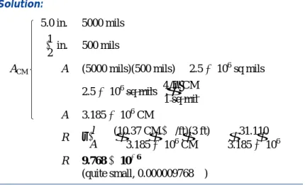
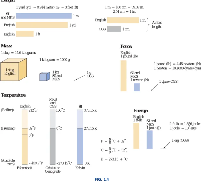
Simple algebraic manipulation will give a solution for any of the three variables. In the picture, pay attention to the relatively small size of the units of measurement for the CGS system.
SIGNIFICANT FIGURES, ACCURACY, AND ROUNDING OFF
When adding or subtracting approximate numbers, the entry with the lowest level of accuracy determines the format of the solution. EXAMPLE 1.1 Perform the indicated operations with the following approximate numbers and round to the appropriate level of accuracy.
POWERS OF TEN
Moving to the right indicates a positive power of ten, while moving to the left indicates a negative power. Equation (1.2) clearly shows that moving a power of ten from the denominator to the numerator, or vice versa, simply requires changing the sign of the power.
Basic Arithmetic Operations
1.9) which in turn allows the separation of the operation with the powers of ten of the multipliers. Determine the power-of-ten component by multiplying the power of ten by the power to be determined.
Fixed-Point, Floating-Point, Scientific, and Engineering Notation
One is the product of two numbers in the power-of-ten format, while the other is a number in the power-of-ten format raised to a power. This restriction of the type tenses is because specific type tenses have been assigned prefixes, which will be introduced in the next few sections.
Prefixes
CONVERSION BETWEEN LEVELS OF POWERS OF TEN
The process is not difficult if we simply consider that an increase or decrease in the power of ten must be associated with an opposite effect on the multiplier. CONVERSION WITHIN SYSTEMS OF UNITS AND BETWEEN SYSTEMS OF UNITS IS 19 Since the power of ten will be reduced by a factor of three, it is.
CONVERSION WITHIN AND BETWEEN SYSTEMS OF UNITS
Set up the conversion factor to form a numerical value of (1) with the unit of measurement to be removed from the original quantity in the denominator. Perform the required math to obtain the correct size for the remaining unit of measurement.
I S SYMBOLS 21
SYMBOLS
CONVERSION TABLES
CALCULATORS
Initial Settings
Order of Operations
COMPUTER ANALYSIS
The use of computers in the educational process has grown exponentially in the last decade. For some students, the thought of having to become proficient in using a computer can result in feeling insecure and uncomfortable.
Languages
This text includes C in its development due to its growing popularity in the educational community. Clanguage was introduced as an extension of the C language to help write complex programs using an improved, modular, top-down approach.
Software Packages
A proper exposure to C would require a course in itself or at least a comprehensive supplemental program to fill the many gaps in this text's presentation. There is no requirement for the student to achieve all three in order to continue with the content of this text.
PROBLEMS
10 9 24. Perform the following conversions
Which of the four unit systems shown in Table 1.1 has the smallest units for length, mass, and force. Why do you think the units of measurement for the SI system were chosen as listed in Table 1.1.
GLOSSARY
MKS System System of units that uses the Meter, Kilogram, and Second as the basic units of measurement. Fixed-point notation Notation using a decimal point in a specific place to determine the size of a number.
Current and Voltage
ATOMS AND THEIR STRUCTURE
So the mass of the proton (or neutron) is about 1836 times that of the electron. For the hydrogen atom, the radius of the smallest orbit followed by the electron is about 5 1011 m.
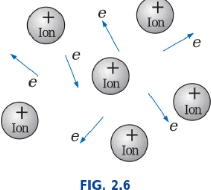
CURRENT
The negative terminal is a "supply" of electrons that must be drawn from as the electrons in the copper wire drift toward the positive terminal. The SI abbreviation for each quantity in Eq. 2.2) is found to the right of the equation.
Safety Considerations
VOLTAGE
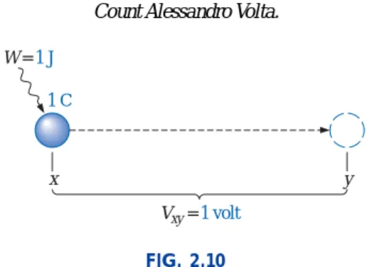
A potential difference of 1 volt (V) exists between two points if 1 joule (J) of energy is exchanged by moving 1 coulomb (C) of charge between the two points. Voltage difference: The algebraic difference in voltage (or potential) between two points in the system.
FIXED (dc) SUPPLIES
The lead-acid battery is charged by a constant voltage source, which allows the current to vary as determined by the condition of the battery. The lower the capacity level of the battery when charging, the higher the temperature of the cell.
- CONDUCTORS AND INSULATORS
- SEMICONDUCTORS
- AMMETERS AND VOLTMETERS
- APPLICATIONS
A scaled reading is obtained when the polarities on the terminals of the ammeter are such that the current of the system enters the positive terminal. The introduction of a meter in an electrical/electronic system raises the question of whether the meter will influence the behavior of the system.
Flashlight
The positive end of the battery is always connected to a flat spring connection or to the cell to be used. If you look carefully at the bulb, you will find that the suction connected to the positive end of the battery is insulated by the jacket around the base of the bulb.
12-V Car Battery Charger
If it charges at the 6-A level, fewer turns of the primary are in the circuit, and the ratio drops. 2.30(b) the large plate that carries the current from the rectifier (diode) configuration to the positive terminal of the battery.
Answering Machines/Phones dc Supply
INTRODUCTION
This opposition, due to the collisions between electrons and between electrons and other atoms in the material, which converts electrical energy into another form of energy such as heat, is called the resistance of the material. The unit of measurement of resistance is the ohm, for which is the symbol, the capital Greek letter omega.
Resistance
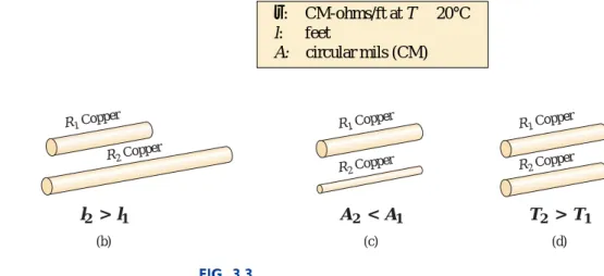
- RESISTANCE: CIRCULAR WIRES
- WIRE TABLES
- RESISTANCE: METRIC UNITS
- TEMPERATURE EFFECTS
Note that conductor area is measured in circular mils (CM) and not square meters, inches, etc., as determined by the equation. The unit of measurement for r can be determined from Eq. 3.1) by first solving for rand and then substituting the units of the other quantities.
Conductors
Resistance in IC design is usually in units of ohm-centimeters, although tables often provide rin ohm-meters or microohm-centimeters. In fact, thermal energy will only increase the intensity of the random movement of particles in the material and make it increasingly difficult to establish a general drift of electrons in any direction.
Semiconductors
Insulators
Inferred Absolute Temperature
For T1 and T2 less than zero, x and y are less than 234.5 °C, and the distances are the differences between the derived absolute temperature and the temperature of interest. 3.6) where |T1| indicates that the derived absolute temperature of the material in question is inserted as a positive value into the equation.
Temperature Coefficient of Resistance
PPM/°C
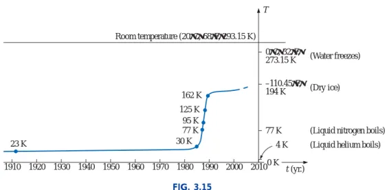
SUPERCONDUCTORS
However, this goal no longer seems feasible unless there is a major breakthrough in the near future. Recently, IBM achieved a level of 4 MA/cm2 at 77 K, which allows the use of superconductors in the design of some of the next-generation high-speed computers.
TYPES OF RESISTORS Fixed Resistors
The relative sizes of the molded composite resistors for different wattage ratings are shown in Fig. Several other types of fixed resistors using high resistance wire or metal films are shown in Fig.
Variable Resistors
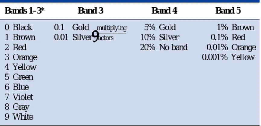
- COLOR CODING AND STANDARD RESISTOR VALUES
- CONDUCTANCE
- OHMMETERS
- THERMISTORS
- PHOTOCONDUCTIVE CELL
- VARISTORS
- APPLICATIONS
In general, however, the resistance of a resistor can be measured by simply connecting the two leads of the meter across the resistor as shown in the figure. Note that at a certain "firing voltage" the current rises rapidly, and the voltage is limited to a level just above this firing potential.
Electric Baseboard Heating Element
3.1) and measuring 8 mils in diameter, and assuming for the moment that it is pure nichrome, a resistor 7 ft. long. Closing the top or bottom of the unit would effectively eliminate the effect of convection and the room would not heat up.
Dimmer Control in an Automobile
This concern is the primary reason for the thermal protective element introduced above and shown in Fig. appear. Further comments regarding the power levels and resistance levels will be reserved for the chapters that follow.
Strain Gauges
MATHCAD
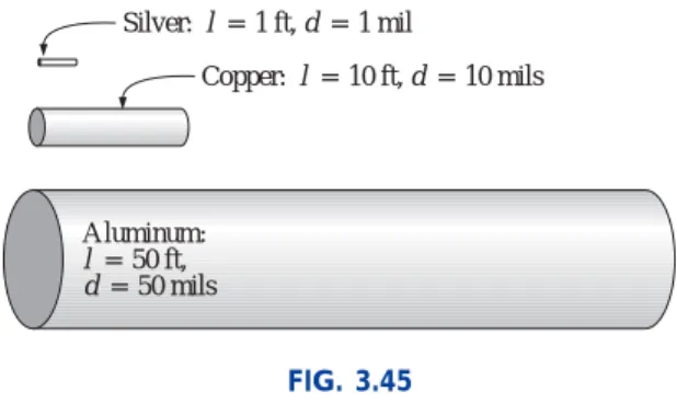
Without working out the numerical solution, determine whether the resistance of the rod (aluminum or copper) will increase or decrease with an increase in length. If the sheet resistance of a tin oxide sample is 100, what is the thickness of the oxide layer.
Ohm’s Law, Power, and Energy
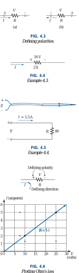
- OHM’S LAW
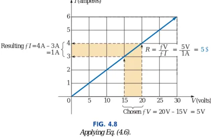
- PLOTTING OHM’S LAW
- POWER
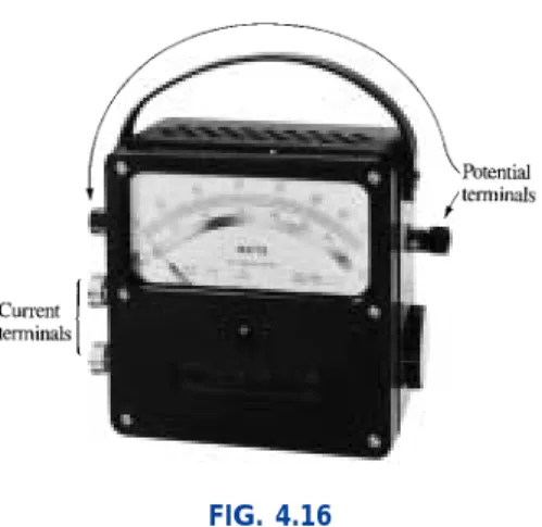
- WATTMETERS
- EFFICIENCY
- ENERGY
- CIRCUIT BREAKERS, GFCIs, AND FUSES
- APPLICATIONS Microwave Oven
Power can be dissipated or absorbed as determined by voltage polarity and current direction. If the current coils (CC) and potential coils (PC) of the wattmeter are connected as shown in Fig.
Household Wiring
COMPUTER ANALYSIS
Over time you will be absolutely satisfied with the results you can get using computer methods. In a later chapter, the C programming language will be introduced in some detail to demonstrate how a user can control the analysis procedure and how the results are displayed.
PSpice
Click OK and a third toolbar will appear at the top of the screen with some keys enabled. Type in the correct label or value, click OK and the number will change on the screen.
Electronics Workbench (EWB)
INTRODUCTION
The positive terminal attracts the electrons through the wire at the same rate at which electrons are supplied by the negative terminal. As long as the battery is connected in the circuit and retains its terminal characteristics, the current (dc) through the circuit will not change in magnitude or direction.
Series Circuits
- SERIES CIRCUITS
- VOLTAGE SOURCES IN SERIES
- KIRCHHOFF’S VOLTAGE LAW
- INTERCHANGING SERIES ELEMENTS
- VOLTAGE DIVIDER RULE
- NOTATION
Note that the format is for V1 and V2. voltage divider rule) (5.10) where Vxi is the voltage across Rx, E is the impressed voltage across the series elements, and RT is the total resistance of the series circuit. Nor is it necessary that the voltage E in the equation be the source voltage of the network.
Voltage Sources and Ground
Double-Subscript Notation
Since a is the first subscript to Vab, point a must have a higher potential than point b if Vabis is to have a positive value. If point b indeed has a higher potential than point a, then Vab will have a negative value, as indicated in Fig.
Single-Subscript Notation
General Comments
- INTERNAL RESISTANCE OF VOLTAGE SOURCES
- VOLTAGE REGULATION
- MEASUREMENT TECHNIQUES
- APPLICATIONS Holiday Lights
A plot of the output voltage versus current appears in Fig. 5.53 for the DC generator with the circuit representation of Fig. For the double-subscript notation, always connect the red lead to the first subscript and the black lead to the second; that is, to increase the voltage Vabin Fig. 5.60 to measure, connect the red lead to point a and the black.
Microwave Oven
5.63(d) the hot line and the return are connected to each group, with the connections to the metal paddles of the plug as shown in Fig. In the next chapter we will find that the current drawn from the wall outlet for parallel loads is the sum of the current in each branch.
Series Alarm Circuit
COMPUTER ANALYSIS PSpice
To begin building the circuit, select Place a Part Key (the second one down) to open the Place Part dialog box. To simulate, select the New Simulation Profile button (which appears as a data sheet on the second toolbar with a star in the top left corner) to open the New Simulation dialog.
Electronics Workbench (EWB)
Determine the current I (with direction) and the voltage V (with polarity) for the networks of Fig. Using schematics, determine the current I and the voltage across each resistor for the network of Fig.
Parallel Circuits
INTRODUCTION
PARALLEL ELEMENTS
The parallel combination of 1 and 2 is then in series with element 3 due to the common endpoint b. 6.4 elements 1 and 2 are in series due to common point a, but the series combination of 1 and 2 is in parallel with element 3 as determined by the common terminals at b and c.
TOTAL CONDUCTANCE AND RESISTANCE
EXAMPLE 6.2 Determine the effect on the total conductance and resistance of the network of Fig. The total resistance of parallel resistors is always less than the value of the smallest resistance.
PARALLEL CIRCUITS
In each case, the total resistance of the network decreased by increasing the additional parallel resistive element, no matter how large or small it was. Note also that the total resistance is also less than the resistance of the smallest element in parallel.
In addition, each individual division by 1 is separated by parentheses to ensure that the division operation is performed before each quantity is added to the adjacent factor. Finally, keep in mind that Mathcad parentheses must enclose each individual denominator expression before placing the appropriate parenthesis in place.
KIRCHHOFF’S CURRENT LAW
Even though the elements are not in series or parallel, Kirchhoff's current law can be applied to determine all the unknown currents. The application of Kirchhoff's current law is not limited to networks where all the internal connections are known or visible.
CURRENT DIVIDER RULE
In other words, the current through each parallel branch is equal to the product of the total resistance of the parallel branches and the input current divided by the resistance of the branch through which the current is to be determined. In other words, for two parallel branches, the current through each branch is equal to the product of the other parallel resistance and the input current divided by the sum (not the total parallel resistance) of the two parallel resistances.
VOLTAGE SOURCES IN PARALLEL
6.40, the current value of the combination is determined by Is I1I2 at the same terminal voltage. If two batteries with different terminal voltages were placed in parallel, both would be left ineffective or damaged because the terminal voltage of the larger battery would try to drop rapidly to the lower supply.
OPEN AND SHORT CIRCUITS
A short circuit is a very low resistance, direct connection between two terminals of a network, as shown in Fig. The voltage across the network is the same as that across the short circuit and will be zero volts, as in Fig.
VOLTMETERS: LOADING EFFECT
Most digital multimeters have internal resistance levels in excess of 10 Mon on all voltage scales, while the internal resistance of a VOM is sensitive to the selected scale. To determine the resistance of each VOM scale setting in voltmeter mode, simply multiply the scale setting's maximum voltage by the meter's ohm/volt (/V) rating, which is usually found on the bottom of the meter's face. .
Measurement Techniques
TROUBLESHOOTING TECHNIQUES
The fact that Va20 V immediately tells us that the connections are true from the power supply ground to point a. A careful check of the resistor fitted reveals that an 8 resistor has been used instead of the required 8 resistor - an incorrect reading of the color code.
APPLICATIONS Car System
In other words, each component is connected at one end to the battery and at the other end to ground or the chassis of the car. When the car starts, the starter relay opens and the battery can focus on the working components of the car.
Parallel Computer Bus Connections
For all vehicles manufactured in the United States and some vehicles manufactured in European countries, the return path to the battery through the ground terminal is actually through the chassis of the car. In some European cars made of a mixture of materials such as metal, plastic and rubber, the return path through the metal chassis is lost, so two wires must be connected to each electrical load on the car.
House Wiring
Some details of just one section of the total machine network are given in Fig. Each complete branch of the circuit receives a full 120 V or 208 V, with the current determined by the applied load.