This project work was carried out by them in the laboratories of the Department of Electrical and Electronic Engineering under the Faculty of Engineering, Sonargaon University (SU) in partial fulfillment of the requirements for the degree of Bachelor of Science in Electrical and Electronic Engineering. At first we would like to express our gratitude to the University Authority for allowing us to do our practicum. Majharul Islam, Lecturer, Department of Electrical and Electronic Engineering, SU−Sonargaon University, Dhaka, for his valuable and patient advice, sympathetic assistance, cooperation, contribution of new idea.
Finally, we would like to once again thank the respected Vice-Rector of SU, Professor Dr. Abul Bashar, also the head of the department of SU, electrical engineering and electronics, professor dr. Light Dependent Resistor (LDR) sensors are required in an automatic lamp system.
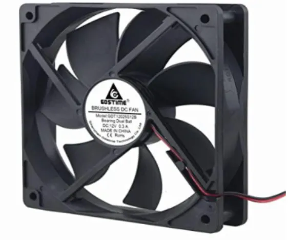
Then for the fan, it can also turn on automatically when the temperature is greater than 28°C and the fan speed can also be adjusted. The fan can also turn off automatically when the temperature is less than 28°C, it can also automatically count the visitors shown on the LCD screen which is controlled by the sensor.
INTRODUCTION
- Introduction
- Background
- Problem Statement
- Project Objective
- Goal of the Research Work
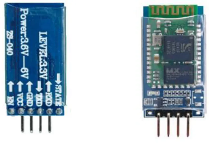
Home automation system is the subset of automation system that allows us to control home appliances like light, door, fan, air conditioner, etc. in an intelligent way. Home automation system can also provide home security and emergency systems to be activated when needed. If Bluetooth provides a low output signal to the microcontroller input, the output is turned off.
In today's world, many institutions are made up of lots of commercial buildings, where room lights and fans are not automatically controlled at all. In other words, manual systems are used in many buildings where lights and fans have to be switched on and off. A person may also forget to turn off the light and fan when leaving the room. This project herein, in operation to control these, explores an automated home light and fan control system to curb the challenge to numerous institutions, businesses and government agencies. .
The ability to automatically control light and fan would allow users to feel comfortable without physically checking. The main goal of this project is to design and implement a Home Automation System that can be produced at a low cost with effective and competitive use.
HARDWARE COMPONENTS
Introduction
System Implementation
Our goal is to implement a low-cost project so that we create a simple system that can meet the project demand and goal.
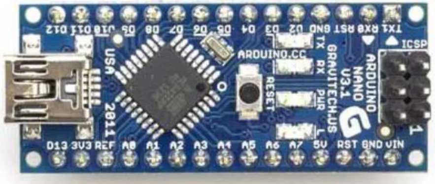
Arduino Nano
Technical specifications
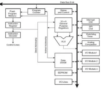
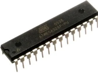
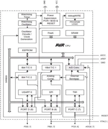
Microcontroller ATMEGA328P
By executing powerful instructions in a single clock cycle, the ATmega328/P achieves throughput close to 1MIPS per MHz. The ATmega328/P offers the following features: 32 Kbytes of System Programmable Flash with Read-While-Write capability, 1 Kbytes of EEPROM, 2 Kbytes of SRAM, 23 General Purpose I/O Lines, 32 General Purpose Work Registers, Counters real-time clock (RTC), three flexible timer/counters with compare and PWM modes, 1 programmable serial USART, 1 byte-oriented 2-wire serial interface (I2C), a 6-channel 10-bit ADC (8 channels in TQFP and QFN/MLF packages), a programmable Watchdog Timer with internal oscillator, an SPI serial port, and six software-selectable power saving modes. In power saving mode, the asynchronous timer continues to run, allowing the user to maintain a timer base while the rest of the device is asleep.
In Standby mode, the crystal/resonator oscillator runs while the rest of the device sleeps. The Boot program can use any interface to download the application program into Application Flash memory. Software in the Boot Flash section will continue to run while the Application Flash section is updated, providing true Read-While-Write operation.
2KB SRAM, 23 general I/O lines, 32 general work registers, three flexible timer/counters with compare modes, internal and external interrupts, serial programmable USART, a byte-oriented 2-wire serial interface, SPI serial port, a 6-channel 10-bit A/D converter (8-channel in TQFP and QFN/MLF packages), programmable watchdog timer with internal oscillator and five software-selectable power saving modes. By executing powerful instructions in a single clock cycle, the device achieves throughput approaching 1 MIPS per MHz, which balances power consumption and processing speed.
Power supply, inputs and outputs
Digital inputs and outputs
- Communication system
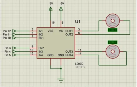
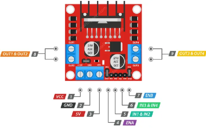
- L298 (DC motor driver)
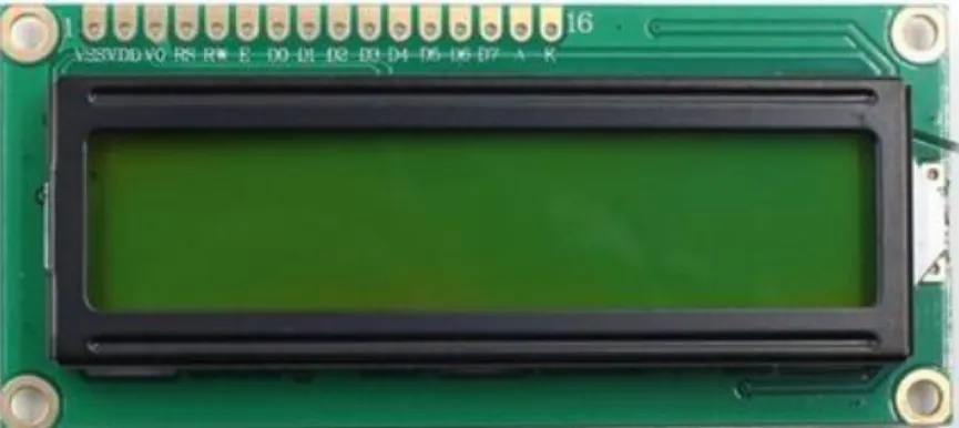
- LCD Display
- Light Dependent Resistor
- Resistor
- Buck Converter Module
- Temperature Sensor
- Vero board
- Soldering Wires
- Jumper Wire
- Others devices
- Arduino software
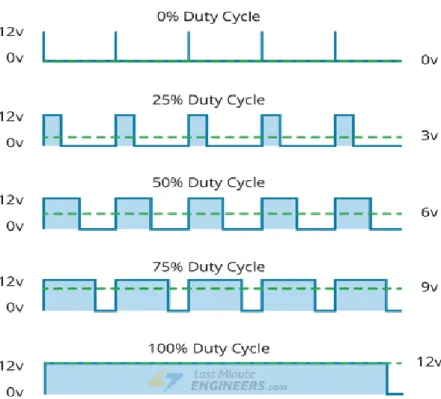
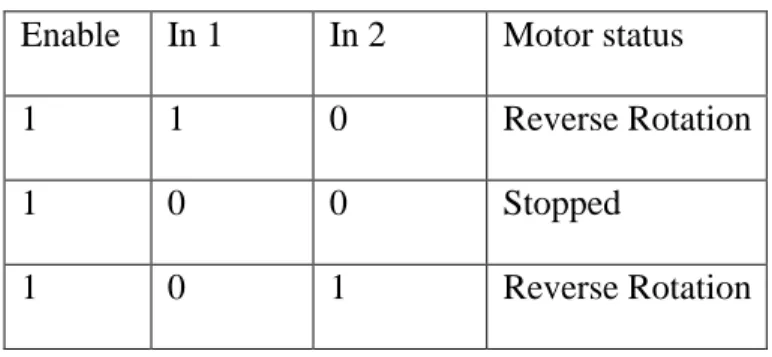
The motors are rotated based on the inputs provided across the input pins as either LOGIC 0 or LOGIC 1. Simply put, you need to provide Logic 0 or 1 across the input pins to run the motor. PWM is a technique in which the average value of the input voltage is adjusted by sending a series of ON-OFF pulses. Keep in mind that with the 5V-EN jumper in place, you will need to supply 2 volts extra volts than the motor's actual voltage requirement, to get the maximum speed out of your motor.
If the 5V-EN jumper is in place, this pin acts as an output and can be used to power up your Arduino. Pulling this pin HIGH (holding the jumper in place) will cause the motor to spin, pulling it LOW will stop the motor. If you pull this pin HIGH (holding the jumper in place), motor B will spin, and if you pull it LOW, the motor will stop.
For example, a character positive LCD with a background will have black letters on a background that is the color of the background, and a character negative LCD will have a black background with letters the same color as the background. In the absence of light, the resistance can be on the order of 10K ohms to 15K ohms and is called the dark resistance. The figure below shows that when the torch is switched on, the resistance of the LDR drops, allowing current to pass through it, is shown in figure.
Variable resistors can be used to adjust circuit elements (such as a volume control or lamp dimmer), or as sensing devices for heat, light, humidity, force, or chemical activity. The nominal resistance value falls within the manufacturing tolerance shown on the component. The basic operation of the buck converter has the current in an inductor controlled by two switches.
NTC thermistors are the most common, and are the type we will use in this project. It is usually also known by the name of the first item Vero board, which is a trademark of the British organization Vero Technologies Ltd. The smart microcontroller unit called Arduino Uno can be programmed using the Arduino software.
First, select "Arduino Uno from the Tools, Board menu (according to the microcontroller of your board). The IC used named as ATmega328 on the Arduino Uno is burned with a boot loader that allows you to upload new code to it without using an external hardware programmer.It refers to data that has already been received and is available in the port's buffer.
CHAPTER-3
Design &Working Methodology
Introduction
System Overview
Circuit Diagram
Project Implementation
Results and Cost Analysis
Introduction
Result
If fewer people enter the house, you don't need to turn on all the appliances in it. If maximum persons are in it, we have to turn ON all the devices without delay. To overcome these types of problems, we have developed a system that can support all these tricks.
This paper covers the characteristics of the capacity of the monitor, hardware description, the use of different types of sensors.
Costing
Discussion and Conclusion
- Discussion
- Advantage
- Application
- Limitation
- Conclusion
- Future Recommendation
The working procedure of this project is very simple, but we face some limitations while executing this project. In this experimental setup, we can turn the devices ON and OFF automatically as needed. This concept not only ensures that our work will be useful in the future, but also gives us the flexibility to adapt and expand as needs change.
In this paper, we have developed a real-time model that can automatically control and monitor the overall status of all devices in any place, such as home, shopping mall, theater, school, college, bus station, etc., without human intervention. An automated home can be a very simple set of controls, or it can be highly automated, where every device that is plugged into an electrical supply is controlled remotely. It controls the entrances and exits from the home so we don't have to check manually.
This system has many advantages such as simple structure, small size, low power consumption, low cost and stable. In this project, we develop a general purpose electronic circuit design that can show automatic light intensity control and fan control based on temperature LCD display showing temperature and visitor counter, it can also be used detector fire and alarm circuit This project is the summary of the smart home system The project has been successfully developed and met. It is possible to develop this project in many ways, as IOT can be applied to observe the load and form of visitors anywhere in the world.
Appendix