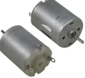
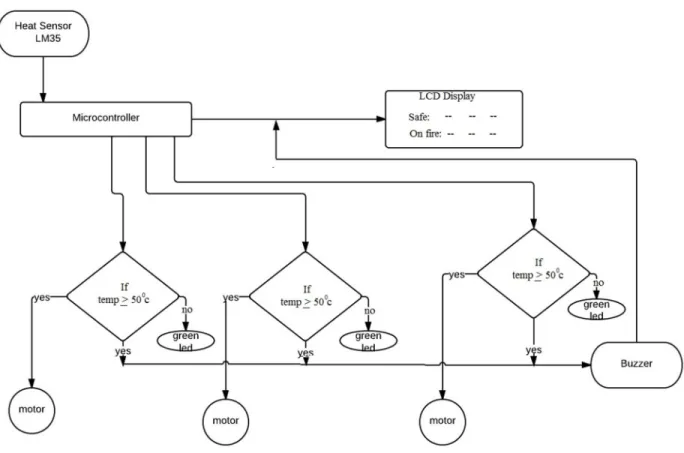
Shamsul Alam, Dean, Faculty of Engineering (FE) and Professor Dr. Md. Fayzur Rahman, Head, Department of EEE for their kind help in completing our thesis and also to other faculty members and the staff of EEE Department of Daffodil International University. The project has three main systems, 1) the tracking system, 2) the monitoring system and 3) the device system. Then it runs the emergency exit motor to escape and the water pump motor to the affected zone to stop the fire.
When a sensor is set for zone 1 sensing the primary source of fire (smoke), it will activate in zone 1 and the microcontroller will receive this signal as a high pulse, so the input pin of the microcontroller will be high and the response on the output pin the LCD will be connected. the show will appear. Popular security system companies are ADT Security Service and Chubb Alarm.

Goal of the Research Work
Problem Identification
Project Objectives
The microcontroller-based fire alarm system described in this thesis could be the best to save lives and reduce property losses at a low cost. This fire alarm system may also include a heat and flame detector connected in parallel. ii). The microcontroller is used as the heart of this fire alarm system that controls all the operations involved. iii).
The fire alarm system is able to locate and identify the source of the fire and is monitored using the monitoring system. iv) Ability to display the output of each sensor in the monitoring system.
Thesis Structure
Theoretical Background
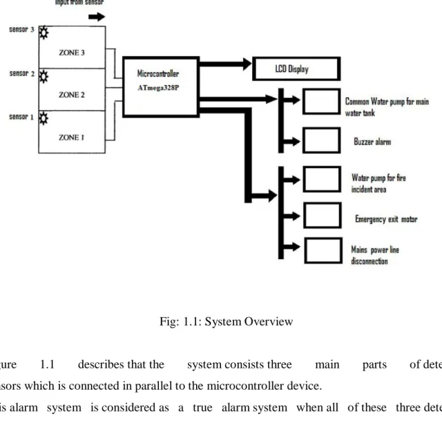
- System Overview
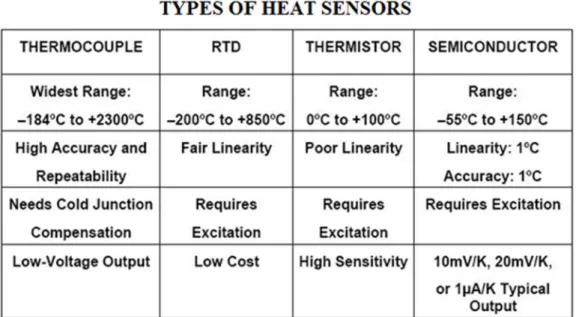
- Heat Detector
- Thermocouple
- Resistance Temperature Devices (RTD)
- Thermistor
- Semiconductor Diode
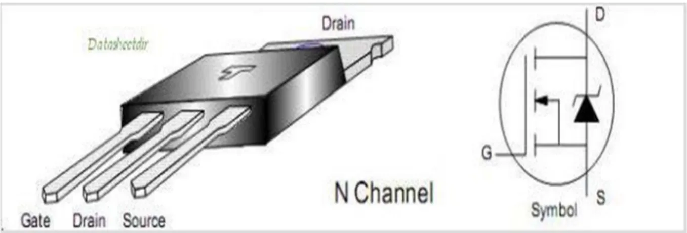
- N-MOSFET
- BC548 NPN transistor
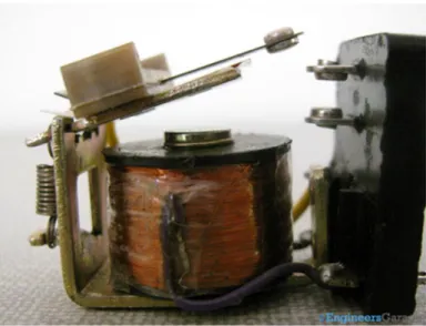
- Relay
- Arduino Platform
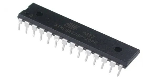
- ATmega328P Microcontroller
- Output Appliance
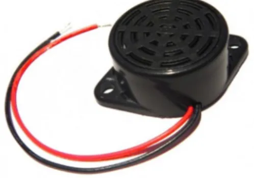
- Buzzer
- DC motor
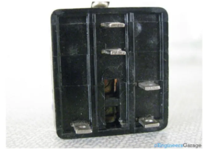
Two terminals are used to provide the DC input voltage also known as the relay operating voltage. The rest of the three terminals are used to connect the high voltage AC circuit. The internal structure of the relay is shown in the image above, which is embedded inside the plastic cover.
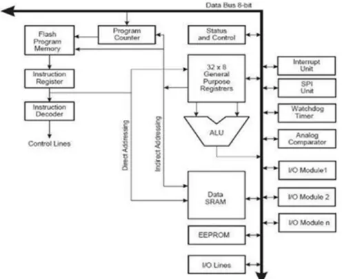
Arduino Uno is one of the microcontroller boards manufactured by the Arduino and it is a microcontroller board based on Atmel's ATmega328P microcontroller. The central processing unit (CPU) is the brain of the microcontroller that controls the execution of the program. As mentioned in section 2.1.2, the CPU is the brain of the microcontroller that controls the execution of the program.
Stack stores the return address of the program counter during interrupts and sub routine calls, which is allocated in the general data SRAM.
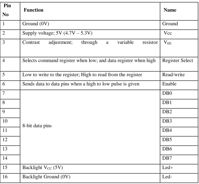
Liquid Crystal Display
It is used to display the character in ASCII code form which means that the data for the character that is sent from the controller to the LCD must be in 8-bit ASCII representation. The characters to be displayed on the LCD panel must be characters that are available in the character table of the LCD data sheet. The system is using LCD to preview the current temperature value and engine speed level.
Commonly available LCD screen in the market for normal displays in the projects is 2x16 pin LCD screen, which is easily available. Talking about the specs, it has 8 data pins, 3 control pins and 5 pins for GND and VCC connections. Another LCD screen used is 2x8 pin LCD screen but it was expensive and has better display but compromises in price and display help achieve this.
The display and light intensity are also adjustable, making it suitable for day and night use for better viewing. 4 Selects command register when low; and data register when high Register Select 5 Low to write to the register; High to read from register Read/Write 6 Sends data to data pins when a high to low pulse is given Enable 7.
System Design and Development
System Implementation
System Architecture
- Microcontroller Module
- Programming ATmega328P
- Oscillator
- Sensory Module
- LCD Modules
Page | 22 Since the system requires the use of a microcontroller, the design consists of two parts, hardware and software. Each level is sensed by an input that will trigger the same output level and output status and temperature display on the LCD panel. The controller is the main part of the system where this hardware will control the entire process flow according to the embedded programming.
Microcontroller functions are limited by manufacturers or specific model types. Page | 25 ATmega328P is chosen as the controller for the project because it offers various functions and is useful for the system and it is mostly available in the market. Since the microcontroller needs a clock, two capacitors and a crystal are used to produce 16 Mhz, two capacitors connected to pin number 9 and 10 of the microcontroller.
It is used as a basic Celsius temperature sensor, which can detect temperatures from +2 ºC to +250 ºC. The 5V power supply is used from the Arduino Board ports and the input and output are connected to the Arduino I/O ports. The analog input port A0 of the Arduino board is used as the input port, and the 5V output port of the Arduino board is used as the power supply for the LM35.
Since the sensor is used as a basic Celsius temperature sensor, any external circuitry is not required and the output of the sensor can be driven directly to the input port of the board. Page | 31 The microcontroller reads the output voltage from the sensor every second using the function analogRead. The temperature sensor Device senses the temperature and gives the output as a display in the LCD.
3.2.3.1 2rows x 16 columns text LCD
- Buzzer
- Voltage Regulator
- System development
- Software Configuration
The temperature is calculated from the output voltage using the formula shown in listing 3 and if it exceeds the limit defined in the software, it will automatically send a signal to the microcontroller and then the microcontroller will instruct the motor to to run in the specified Zone. First, all the hardware units of the system were tested and ensured to be in good working order. Then each unit was individually interfaced with the microcontroller board and implemented and driven with the software according to the necessity of the application.
The second device was not tested until the first device gave the expected result and until it failed to function according to the necessity of the application. After all the devices worked properly, the devices were kept together and then the whole system was developed and tested. It was easy to find out the bugs and the problem of the system as the behavior of each device was known while testing it.
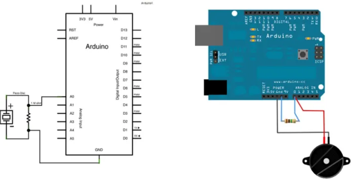
It would be impossible to find out the problems and the bugs in the system if the system was developed and tested after it was completed. To protect transistor and microcontroller from burnout, we used a 1kΩ resistor between the base of the transistor and microcontroller's output pin. For instant smoke detection, we can use a high sensitivity smoke detection detector to give a high pulse to the input pin of the microcontroller from which it will get fictitious activity as per program installed in the microcontroller.
The software written on the platform can be uploaded to the microcontroller (ie the arduino board) using Arduino IDE software. The entire program is written in the platform in the C language code, which can be uploaded to the board with a simple upload button. Basically, the project is integration of the software (C language code) used to interface and implement the sensors.
Result & Discussions
Result
- Project Evaluation
- System Features
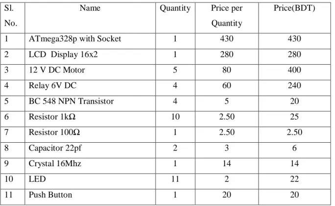
- Costing
With the development of technology, the concept of simple home has also changed into smart home and the concept of home has changed drastically during the last decade. The mobile phone can be used for different purposes with the help of the applications developed for the phones. The temperature of the premises where the sensors are installed can be known at any time before the critical limit set by the user is reached.
The project can be expanded by increasing the number of sensors used along with an increase in the number of installation locations. However, many hardware and software errors were experienced during the development of the application. There were many errors in the software as well as connection errors in the hardware, which came along with the development of the application and which were solved individually.
Despite reading the data sheet for the sensors before using them, accidentally connecting the wrong pins burned out the microcontroller. Similarly, there were some hardware errors while connecting the sensors and the LED to the microcontroller. The purpose as defined earlier was to detect fire, confirm its presence by checking through several sensors and then indicate its position on an output device and alarm a buzzer to inform the surroundings of the presence of the fire.
The project also includes some excellent features that make the fire alarm system more or less sensitive and place the fire alarm system in different locations. i) Determines the exact location of the fire. ii) Indicates the presence of fire without any delay. iii) Sound the alarm loudly, allowing those around to take necessary measures to get away from the fire and take steps to extinguish the fire. iv) Provides flexibility to reduce or increase the sensitivity of the sensors for detecting fire. v). By connecting several sensors to a single microcontroller chip, the cost of the fire alarm systems is reduced. vi) Rejects false alarms or any ambiguity. i) Detects the fire from one location at a time. If there is a fire in more than three locations, the system can only detect and localize in three locations. ii). No data is kept in the system, which deprives us of any kind of analysis that could be beneficial for the improvement of the existing system. iii).
Conclusion & Future Scope
Conclusion
Future Scope
We can even combine IR sensor, light sensor, smoke detector, pressure sensor, gas sensor with this project to make this project more efficient.
![Fig 2.7: Arduino Uno R3 Reprinted from the Arduino Board Uno [2]](https://thumb-ap.123doks.com/thumbv2/filepdfnet/10815411.0/20.918.224.713.463.751/fig-arduino-uno-r3-reprinted-arduino-board-uno.webp)