STAND-ALONE PHOTOVOLTAIC (PV) SYSTEM DESIGN
GHAFAR BIN JENAL
A Report is submitted in Partial Fulfillment of Requirements for the Degree of Bachelor of Electrical Engineering (Industry Power)
Faculty of Electrical Engineering
UNIVERSITI TEKNIKAL MALAYSIA MELAKA
“I hereby declared that I have read through this report entitle Stand-Alone Photovoltaic (PV) System Design and found that it has comply the partial fulfillment for awarding the degree of Bachelor of Electrical Engineering (Industrial Power).”
Signature : ………
Supervisor‟s Name : EN ASRI BIN DIN
“I hereby declared that this report entitle Stand-Alone Photovoltaic (PV) System Design is the result of my own research except as cited in the references. The report has not been accepted for any degree and is not concurrently submitted in candidature of any other degree.
Signature : ……….
Name : GHAFAR BIN JENAL
Dedicated to my beloved parents …Hj Jenal B. Md Yassin, and Hjh Jamilah Bte Hj Ngah
ACKNOWLEDGEMENT
First and foremost, I thank Allah the Almighty for blessing me to complete my Project Sarjana Muda 2. I would like to enlarge my appreciation to En Asri Bin Din because of the kindness heart to accept me as one of the student under his supervision. Special thanks I dedicated to his for all comments, idea, and a guideline begin from the first day I start this project.
To my beloved family, I would like to forward my obliged to them for their continuous support during my study period, their patience and benevolence. Lastly, I would like to thank to everyone who has contributed during my Project Sarjana Muda 2. Your kindness and cooperation in completion of my paper work is much appreciated.
ABSTRACT
ABSTRAK
TABLE OF CONTENTS
2.1 Introduction of Renewable Energy 3 2.2 Photovoltaic Stand alone system 4
2.3 Grid connected system 5
2.4 Photovoltaic Sub system 6
2.4.1 Module array 6
2.4.2 Charge controller 7
2.4.3 Battery 8
4.2.6 System Specification 37 4.2.6.1 Analysis of System Specification 38 4.2.6.2 Comparison of diff. load consumption 41 4.2.7 Computer Programming 42
5 RECOMMENDATION AND CONCLUSION
5.1 Conclusion 44
5.2 Recommendation 44
REFERENCES 46
LIST OF TABLES
TABLE TITLE PAGE
2.0 Power Efficiency Conversion Factor 11
2.1 Maximum Depth of Discharge 13
2.2 Module Derate Factor Value 15
3.0 Typical Load for Fertigation 20
3.1 Typical Load for Cow Breeder 20
4.0 Battery Electrical Data 31
4.1 Array Electrical Data 33
4.2 PV Module Specifications 34
4.3 Charge Controller Electrical Data 36
4.4 Generator Electrical Data 39
4.5 Inverter Electrical Data 39
4.6 Selecting Inverter System Voltage 40
LIST OF FIGURES
FIGURE TITLE PAGE
2.1 Photovoltaic Hybrid System Block Diagram 4
2.2 Connected System Block Diagram 5
2.3 Module Array 6
2.4 Connection Module in Parallel and Series 7
2.5 Connection Batteries Series and Parallel 8
3.0 Project flow chart 21
4.0 Flow Chart of program 24
4.1 Program Splash Screen 25
4.2 Program Introduction Screen 26
4.3 Technical System Data 27
4.4 Load Selection 28
4.5 Battery Selection 30
4.6 Array Selection 32
4.7 PV Module Specifications 34
4.8 Controller Selection 35
4.9 System Specification 37
LIST OF ABBREVIATIONS
A - Ampere
V - Voltage
W - Watt
Hz - Hertz
Hp - Horse Power
⁰C - Celsius
Ah - Ampere-hour
Ah/day - Ampere-hour per day
LIST OF APPENDICES
APPENDIX TITLE PAGE
A1 Table of load estimation calculation 46
A2 Table of battery sizing calculation 47
A3 Table of array sizing calculation 47
A4 Table of controller sizing calculation 48
A5 Inverter and converter specification 49
B Gantt chart 50
C Example of Meteorology data in Malaysia 51
D Example of array data 52
E Example of battery data 53
F Example of charge controller data 54
G Example of inverter data 55
H Example of generator data 56
CHAPTER 1
INTRODUCTION
1.1 Problem statement
Manual calculation of stand-alone photovoltaic system is the conventional way to sizing the system and a lot calculation required. In this case, longer time needed and the potential to do mistake is high in order to solve the calculation. Moreover, the inaccurate design may contribute to inefficient of spending money, energy and time.
1.2 Project Objective
The main purposes of this project are:
a) Studies and make some research regarding the power consumption that especially used by agricultural and veterinary in remote area.
b) Design the PV stand-alone system including power consumption calculation and sizing the PV sub system.
c) Implement designing of sizing PV sub system into graphical user interface (GUI) using Visual Basic 6.
1.3 Project Scope
CHAPTER 2
LITERATURE REVIEW
2.1 Introduction of Renewable Energy
“Renewable energy is the energy that generated from natural source such as wind, sunlight, tides, rain and geothermal heat which replenishes itself naturally”[4]. Renewable energy technologies include solar power, wind power, mini hydro, biomass and biofuels. Solar energy technologies can provide day lighting and thermal comfort in passive
buildings, potable water via distillation and disinfection, hot water, pumping water and drying crop.
Photovoltaic (PV) is the field of technology and research related to the application of solar cells for energy by converting sunlight directly into electricity. The two principal classifications are grid-connected or utility-interactive systems and stand-alone systems. Photovoltaic systems can be designed to provide DC and/or AC power service, can operate interconnected with or independent of the utility grid, and can be connected with other energy sources and energy storage systems. There are two type of PV systems almost used, grid connected and off grid (stand-alone) [1].
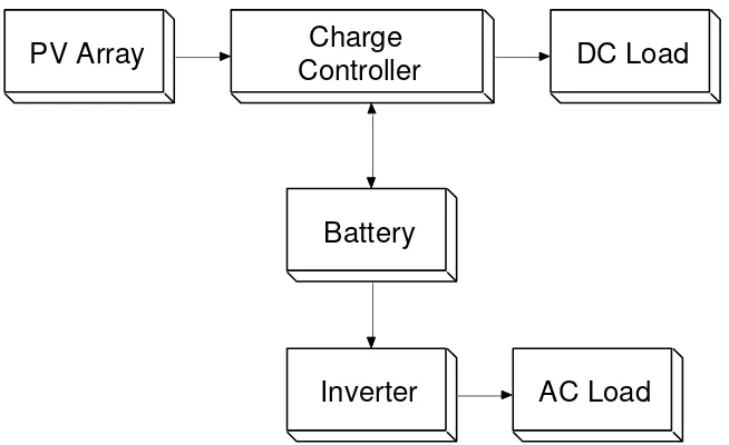
2.2 Stand-alone Photovoltaic system
PV Array Charge
Controller DC Load
Battery
Inverter AC Load
Figure 2.0: Stand-Alone Photovoltaic System Block Diagram
PV Array Charge
Controller DC Load
Battery Inverter
AC Load Generator
Wind turbine Rectifier
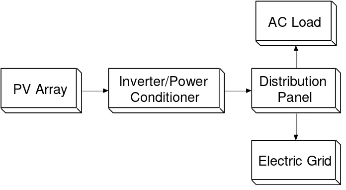
2.3 Grid connected system
Grid-connected or utility-interactive PV systems are designed to operate in parallel with and interconnected with the electric utility grid. The primary component in grid-connected PV systems is the inverter, or power conditioning unit (PCU). The PCU converts the DC power produced by the PV array into AC power consistent with the voltage and power quality requirements of the utility grid, and automatically stops supplying power to the grid when the utility grid is not energized [1]. A bi-directional interface is made between the PV system AC output circuits and the electric utility network, typically at an on-site distribution panel or service entrance.
This allows the AC power produced by the PV system to either supply on-site electrical loads or to back-feed the grid when the PV system output is greater than the on-site load demand. At night and during other periods when the electrical loads are greater than the PV system output, the balance of power required by the loads is received from the electric utility This safety feature is required in all grid-connected PV systems, and ensures that the PV system will not continue to operate and feed back into the utility grid when the grid is down for service or repair. [1] Figure 2.2 show grid connected system block
diagram.
2.4 Photovoltaic Stand-Alone Sub system
In the Photovoltaic Stand-Alone system there are several components. These components functioning to received, storage, regulated and produced the voltage and current for appliances. The component which is includes:
2.4.1 Module array
In the field of photovoltaic, a photovoltaic module is a packaged interconnected assembly of photovoltaic cells, also known as solar cells. An installation of photovoltaic modules or panels is known as a photovoltaic array or a solar panel. The photovoltaic array is a linked collection of photovoltaic modules, which are in turn made of multiple
interconnected solar cells. The cells convert solar energy into direct current electricity via the photovoltaic effect. Most PV arrays use an inverter to convert the DC power produced by the modules into alternating current that can plug into the existing infrastructure to power lights, motors, and other loads. [1]Figure 2.3 show the module array
Figure 2.3: Module Array
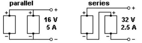
The modules in a PV array are usually first connected in series to obtain the desired
when the amount of sunlight is 1,000 Watts/m2. PV systems are rated based on the maximum combined power output of the PV modules and since the amount of sunlight changes, the power output of the system will vary. [5]
Figure 2.4: Connection Module in Parallel and Series
2.4.2 Charge controller
Charge Controllers or voltage regulators protect batteries from becoming
overcharged, which can shorten their lives as well as the lives of some loads powered by them. Electronic circuit in the regulator measures battery voltage, which rises as the battery state of charge increases. At some voltage, which will be different for different types of batteries and at different temperatures, the regulator will stop the charging of the battery.
When the charging stops, the battery voltage begins to fall. At some preset lower voltage, the regulator allows the charging to resume. The basic functions of a controller are quite simple. Charge controllers block reverse current and prevent battery overcharge. Some controllers also prevent battery over discharge, protect from electrical overload, and display battery status and the flow of power [1].
There are two basic types of controllers used for small PV systems. A shunt
controller redirects or shunts the charging current away from the battery. These controllers require a large heat sink to dissipate the excess current. Most shunt controllers are designed for smaller systems producing 30 amperes or less, a series controller interrupts the
charging current by open-circuiting the PV array. This switching controller is thus limited by the current handling capability of the components used to switch the dc current [1].
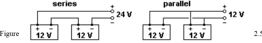
2.4.3 Batteries
hours), When connecting in Parallel the capacity (amp hours) of the battery will double while maintaining the voltage of one of the individual batteries [5]. Figure 2.5 shows the connection series and parallel of the batteries.
Figure 2.5:
Connection Batteries Series and Parallel
2.4.4 Inverter
These devices convert direct-current (dc) electricity to alternating-current electricity (ac). Since PV arrays produce dc electricity, stand-alone PV systems often require an inverter to produce ac electricity for a broad range of loads. The use of large inverters results in approximately 10 percent loss of generated electric energy. However, it is sometimes easier to use such devices rather than to convert all appliances to operate on dc electricity.
Stand-alone inverters typically operate at 12, 24, 48 or 120 volts dc input and creates 120 or 240 volts ac at 50 or 60 hertz. The selection of the inverter input voltage is an important decision because it often dictates the system dc voltage. The shape of the output waveform is an important parameter. Inverters are often categorized according to the type of waveform produced; square wave, modified sine wave, and sine wave. The output waveform depends on the conversion method and the filtering used on the output waveform to eliminate spikes and unwanted frequencies that result when the switching occurs [1].
2.4.5 Conductor (wire)
2.5 Sizing the Stand-Alone PV system
Stand-alone photovoltaic power systems are a low-maintenance, versatile solution to the electric power needs of any “off-grid” application. It is important to determine the correct system size, in term of both peak output and overall annual output, in order to ensure acceptable operation at minimum cost. If the system to large, it will more expensive than necessary without increasing performance levels unsubstantially and therefore the system will be less cost-effective than it could be. However, if too small a system is installed, the availability of the system will be low and the customer will be dissatisfied with the equipment. Again, the cost-effectiveness is reduced. Although the same principles are included in the sizing process, the approach differs somewhat for the stand-alone and grid connected [1].
'Sizing' a system means determining how much energy is required and how many solar modules are needed to generate it.
A solar power system must provide enough energy to replace what is being consumed daily by the loads; lights, appliances, equipment, etc. Plus some additional output to compensate for energy used by the system itself. To develop the whole PV stand- alone system there are several procedure design must be taken [2].
2.5.1 Estimating the electrical load
The first step in the design of a PV system is to determine the load size to be powered. If ac loads exist, inverters must be used. When ac loads dominate the system, system voltage should be compatible with the inverter input. Efficiency of ac inverters is increased with higher input voltage. However, as the voltage is increased, larger PV arrays and storage systems are necessary. On the other hand, higher system voltage corresponds to lower system current. High currents require large wire size, fuses, switches, and connectors. Therefore, keeping the current low will enhance cost-effectiveness [2].
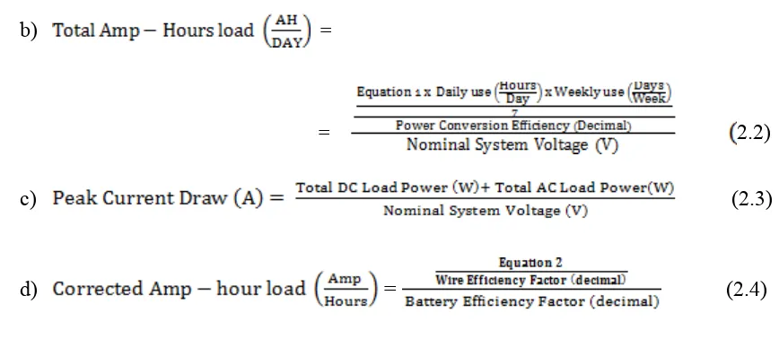
For dc loads operating on voltages different from the system operating voltage, dc converters can be used to obtain adequate voltage to power such loads. Alternatively, the batteries can be tapped if the dc loads are small enough. If the batteries are supplying dc loads, battery charges equalizers must be used to overcome the problem of unequal current draw from series-connected batteries, eliminating possible battery failure [2]. Details see Appendix A1 The formula that used to calculate the electrical power load is:
b) =
= 2.2)
c) (2.3)
d) = (2.4)
Description
i. Power Conversion Efficiency - This factor accounts for power loss in systems using power conditioning components (converters or inverters). If the appliance requires ac power or dc powers at a voltage other system voltage, which should enter the conversion efficiency of the device. If the system does not have the actual efficiency of the converter is being used, the default values will used for initial sizing. Table 2.0 shows the power efficiency conversion factor.
Table 2.0: Power Efficiency Conversion Factor Power Efficiency Conversion Default
DC to AC 0.85
DC to DC 0.9
ii. Nominal system voltage (V) - The designer should enter the desired system voltage. The system voltage is normally the voltage required by the largest loads. Common values are 12 or 24 volts dc and 240 volts ac.