The 1st International Conference on Engineering and ICT, 2007, Melaka, Malaysia
[Type text]
1
Abstract-This report insight the design, fabrication and testing of 2.4 GHz Bandpass Filter developed by using Microstrip Technology. The results acquired through R & D process have been simulated, analyzed and verified by using parallel-coupled lines filter topology, which were later, enhanced by various value-aided software tools such as MATLAB (V 7.0), CorelDraw 12, Microwave Office (2004). For the optimal result, three samples were fabricated with the help of Microwave Office tools. The comparative filter response analyses were carried out with the help of vector network analyzer, which gives the best choice for further analysis and development. Comparative analyses were carried out for the optimization of both experimental and analytical data acquired through the design, simulation, and fabrication and testing process of the bandpass filter. Subsequent results demonstrate, through verification process, that the experimental results (measured) gives more or less same performance compare analytical one (calculated).
Index Term- Band pass filter, filter circuit, microstrip, microwave, telecommunication.
I. INTRODUCTION
ICROWAVE Bandpass filters are presently required in wide applications of wireless communication systems. Many applications require wide band and tunable filters for receivers, which led to the development of highly selective waveguide, coaxial resonator, and electronically tunable filters. For WLAN, satellite communications; low loss narrow-band and low cost filters are demanded resulting to the development of dual mode waveguide and dielectric resonator filters. Mobile communication base-stations require low loss, low cost and high power-handling filters. These requirements lead to advances in coaxial resonator, dielectric resonator, and super-conducting filters.
This paper present design, analyze and fabricate a microstrip bandpass filter for 2.4 GHz . Basic design specifications for a bandpass filter were considered are center frequency and bandwidth. The specifications are given in Table I. below:
fabrication technology microstrip size constraint +/- 3 x 8 cm
price target ≤ 30 RM
circuit board material FR4 substrate thickness 1.6 mm
εr 4.7
characteristic impedance 50 Ω
II. MICROSTRIP FILTER
A. Microstrip
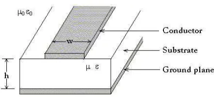
The microstrip belongs to the group of parallel-plate transmission lines and consists of a single ground plane and an open strip conductor separated by a dielectric substrate. Microstrip lines are the most commonly used form of transmission lines for microwave integrated circuits. Also, microstrips are used as circuit components for filters, phase shifters, couplers, resonators and antennas [1].
Fig. 1. Microstrip Line
2.4 GHz Microstrip Band Pass Filter
Abdul Rani Othman
, Chairulsyah Wasli
The 1st International Conference on Engineering and ICT, 2007, Melaka, Malaysia
[Type text]
2
The electromagnetic field in the microstrip line is not confined only to the dielectric and because of the fringing; the effective relative permittivity ε
eff is less than the relative permittivity εr of the substrate [1]. The electromagnetic waves in microstrip propagate in TEM (transverse electric magnetic) mode, which is characterized by electric and magnetic fields that exist only in the plane perpendicular to the axis of the wave propagation.
B. Parallel Couple Microstrip Lines
As in the case of a single microstrip line, a parallel-coupled microstrip arrangement is also a TEM-mode system. The relative polarities of the voltages on the coupled microstrip lines at any specific plane along the structure and at any specific time will be the same or opposite resulting in two different modes of field distribution, namely the even-mode and the odd mode.
Fig. 2. Field Distribution for Coupled Lines
The two field distributions result in even-mode and odd-mode characteristic impedances denoted by Z 0e and Z 0o[2]. These characteristic impedances are major parameters in design procedures. The complete behavior of the parallel-coupled microstrip structure can be obtained by superposition of the effects due to these two modes.
C. Filter
A filter is a device or substance that passes electric currents at certain frequencies or frequency ranges while preventing the passage of others. Based on the frequencies they pass, the filters are classified as low pass filters (LPF), high pass filters (HPF), bandpass filters (BPF) and bandreject filters (BRF). These filter types are best explained based on the characteristics of a normalized low pass filter because characteristics of other filter types can be related to the low pass filter characteristics. The ideal low pass filter is characterized by zero loss and zero ripple in the passband, an infinite attenuation slope at cutoff frequency and infinite attenuation in the stopband.
III. METHODOLOGY
Basic design specifications for a bandpass filter were considered are center frequency and bandwidth. The other specifications are given in Table 1. above. For this research a center frequency of 2.4 GHz, which corresponds to the free-space wavelength of 12.5 cm, was chosen for hand-based dimensions fabrication. With using formula related to calculate dimension of parallel couple filter, found L(length),W(width) , and S(spice) as shown in Table II[3]. The filter designed was fabricated with the aid of Correl Draw 12 and CAD tools to print exact dimension on PCB for simulation purpose. The filter characteristics were measured. As the results of literature review recommendations, +/- 10 % bandwidth, which corresponds to 240 MHz at 2.4 GHz center frequencies, was chosen for further research and development process. The choice of the parallel-coupled lines filter has been explained analytically with the help of Microwave Office 2004 to aid design process for the evaluation of calculated result and simulation frequency response.
A. Design Model
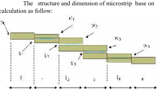
The structure and dimension of microstrip base on calculation as follow:
Fig. 3. Structure of couple line band pass filter microstrip N= 3 , εr = 4.7 (not real scale)
TABLE II
The 1st International Conference on Engineering and ICT, 2007, Melaka, Malaysia
[Type text]
3
Fig.4. Figure for schematic design
IV. RESULT AND DISCUSSION A. Simulation Results
Fig. 5. Graph of Insertion and Return Loss of the Bandpass filter as simulation result
Fig. 6. Physical of Parallel couple microstrip BPF
B. Test Results
(a)
(b)
(c)
Fig. 7. (a), (b), (c) Return loss (S11) for fabrication result sample 1, 2, and 3
The 1st International Conference on Engineering and ICT, 2007, Melaka, Malaysia
[Type text]
4
(a)
(b)
(c)
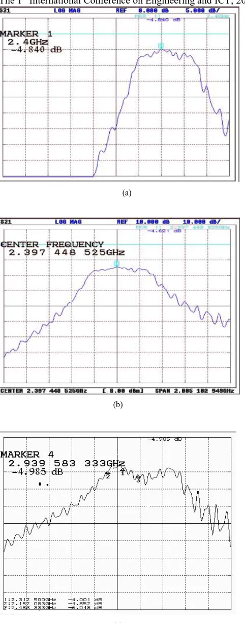
Fig. 8 (a), (b), (c) Insertion loss (S21) for fabrication result sample 1, 2, and
3 respectively
TABLE III
SUMMARY COMPUTATION BETWEEN SPECS SIMULATION RESULT AND TESTING RESULT
The fabrication of three filter samples base on data from Table 1 then measures using Network Analyzer. The sample 1 is the best due to sample 1 have one minimum return loss as Fig. 6. The measured center frequency is 2.4 GHz which is same with the design center frequency. The measured bandwidth was 260 MHz that was found smaller than the desired bandwidth. The Bandwidth give differences of 8 % and got better Return Loss.
V. CONCLUSION
In this paper, the procedure for designing a parallel couple bandpass filter has been presented. The above findings demonstrates that it is very difficult to fabricate a parallel couple bandpass filter for desired specifications not only due to the constraints encountered in Low Tech processing equipment but also errors realized for the unknown parameter which have not yet been included in the calculations.
REFERENCES
[1] I. Bahl and P. Bhartia., “Microwave and solid state Circuit Design”, Wiley., 2003
[2] R. Mongia., “RF and Microwave Coupled Line Circuits,” Artech House., 1999