14
A Water Bath Control System in a Virtual
Laboratory Environment
M. F. Basar and N. Hasim
Abstract—In this paper, the development of a water bath control system in a virtual laboratory environment is discussed. The system proposed is developed using LABVIEW 8.6. This project consists of three stages. The first stage is hardware development, which involves construction of interface circuit to allow communication between plant and computer. The second stage is to build the Fuzzy Logic Controller using LABVIEW software, where fuzzy set and rule base are applied. The final stage is to publish the GUI module onto the web for real-time remote control. An internet based GUI module environment of a water bath temperature control system has successfully been developed using LABVIEW software and published onto the web where it can be fully controlled using Fuzzy Logic Controller developed, and monitored by any user despite of their geographical locations, as long as they have computers with web browsers and internet connection. Thus, this will assure a better and easier understanding of certain subjects, especially control system. With such a facility, laboratory resources can be shared online, laboratory experiments can be carried out away from the site as well as outside the official working hour, and the control subject can be taught in a more meaningful and effective manner to the students.
Index Terms—Fuzzy Logic Controller, GUI Module, Labview Software, Virtual Laboratory, Water Bath.
1 I
NTRODUCTION!
!
"
#
#
$#%&' ( )
2 P
ROJECTO
VERVIEW '* *
$ &' (
2.1 Project Background
In engineering fields, lecturers deliver the information to the students by teaching the concepts, theories and formulas, with the aid of examples and tutorials. Howev-er, all of these are only theory and significantly hard to be understood comprehensively. Furthermore, the students seldom have the opportunity to apply the knowledge of what they learnt in class. Additionally, hands-on experi-ments play a vital role in complementing the theories and concepts taught in the class. Teaching and learning via the internet is more practical due to the fast growth of web technologies.
Virtual laboratories is the best way to provide the stu-dents with practical approach since it is often an issue in allocating the time for students to attend the labs to carry out the experiments with supervision from the lecturers. However, this issue becomes easier if the students can remotely monitor and control the equipment from some-where else to perform the laboratory experiments even during midnight or weekends through the internet. Based from [1], the responses from the students’ show that they are not only appreciate the flexibility of the remote access option, but they also feel that the remote option encou-rages them to take a deep learning approach to the ma-terial.
Another issue is the insufficient of lab equipment due to the increasing number of students each year. It might be too costly to set up several sets of equipments to meet these needs. Many universities and colleagues offer dis-tance learning programs and it might be not practical if the students need to travel to the lab in order to carry out the experiments there.
————————————————
•
!"#$$ % &
• ' (
!"#$$ )
'
Therefore, it would be so much easier to publish the lab instrument onto the web where it can be accessed re-motely regardless of geographical location. Referring to [2], [3] and [4], the web-based laboratory has been devel-oped to serve undergraduate students in the Department of Electrical Engineering at NUS (The National University of Singapore) where the implementation uses video con-ferencing to provide fast and point-to-point visual feed-back to the client, on the happenings in the laboratory and also allows users to control the zoom and viewing angle of the video.
Beside the advantages of saving resources and the greater attraction of such laboratory work for the electric-al engineer, it electric-allow students to learn networking tech-nologies, and they are in a better position to assess the requirements and properties of connected automatic con-trol systems.[5] Moreover, remote laboratory experiments for control engineering education has also been imple-mented in WebLab University of Kragujevac where it has laboratory experiment in control courses that could be remotely controlled (Gantry Crane—implementation based on C# and Coupled tanks—implementation based on LabVIEW).[6] The work in [7] describes the develop-ment of a remote laboratory with some hardware experi-ments based on modulation techniques used in Commu-nication Engineering course.
The works in [2] describes web-based virtual electron-ics laboratories, one on frequency modulation experiment and the other on coupled tank apparatus, a multi-input-multi-output (MIMO) system, developed at National University of Singapore using LabView and Java applet programming. An online laboratory for Microelectronics test circuit utilizing Java applet has also been developed [8].
The work in [9] describes a web-based laboratory for remote control of an inverted pendulum using Matlab and Java programming. A remote laboratory based on experiments for control engineering course has been de-veloped at University of Texas, Arlington using Microsoft Netmeeting and Matlab's Simulink environment [10].
2.2 Objectives of Project
The primary objective of this project is to setup a wa-ter bath, inwa-terfacing system and the server in the lab lo-cated in University Teknikal Malaysia Melaka. The water bath consists of the water tank itself, a temperature sensor (RTD), a heater and a stirrer. An interface system will also be mounted so that the water bath can be controlled through the server computer using the GUI module de-veloped.
Secondly, an internet-based GUI module for virtual laboratory environment of a water bath temperature con-trol system will be developed using LabVIEW. The GUI module will be published onto the internet so that the water bath temperature control system can be either mo-nitored or controlled remotely.
2.4 Fuzzy Logic and Virtual Laboratory
Fuzzy logic is a method of rule-based decision making used for expert systems and process control that follows the rule-of-thumb thought process human beings use [1]. In 1960s, Lotfi Zadeh developed fuzzy set theory, the ba-sis of fuzzy logic. Fuzzy control provides a formal me-thodology for representing, manipulating, and imple-menting a human’s heuristic knowledge about how to control a system [11]. The field of fuzzy sets and logic was first introduced by Lotfi Zadeh [12, 13] and fuzzy control
was first introduced by E. Mamdani [14, 15]. Tuning PID
and fuzzy controllers are well suited problems for simula-tion training where after a simulasimula-tion training; the stu-dents are capable of solving a laboratory control problem about four times faster than without simulation training [16].
Laborato-ry” originates from. This technology greatly enhances the flexibility of laboratory education, and introduces stu-dents to the new paradigm of remote experimentation.
From Fig. 2, apparently, the hardware i.e. the water bath is connected to a computer in the lab which serves as the server. It is controlled using the Graphical User Inter-face module running locally on a LABVIEW platform. In other words, the server computer plays the role of com-municating directly with the hardware through a devel-oped interface system. Meanwhile, the server computer is connected to the network, either to the internet or Local Area Network (LAN).
) 5 8 7.'
The GUI module will also be published onto the net-work and the module is accessible to the worldwide us-ers. Users, or known as the clients from anywhere of the world, can remotely access and control the GUI to control the water bath, as long as they have computers with web browser and connected to the network. Upon the connec-tion to the server as well as the hardware, the client sees the same front panel (GUI) exactly as the local host (serv-er), and also has the exact same functionality presented through the browser. This is a bi-directional operating system, which means, the clients or users will continuous-ly receive real time data from the water bath plant in the lab which varies with time. At the same time, if the clients or users manipulate the control in the GUI from their own computers (client pc), the GUI in the server computer will immediately respond to the changes made and then take action to generate any outputs necessary for experiment stimulus.
and control the lab equipment in the lab which is linked to the internet. This is “real” experiment, rather than per-forming merely simulation or demonstration.
Water bath is a vessel which is usually adiabatic that contains some liquidized food materials in which its ob-jective is to control the temperature of the mixed liquid. The major components of the water bath are a water tank, a heating coil (controlled by a 2 Pole Contactor), a sensor (which is the RTD Sensor) and a stirrer.
The water bath temperature is controlled using Fuzzy Logic control. Users can control the temperature of the water bath using the controllers in the software devel-oped using LABVIEW software. An interactive Graphical User Interface is developed to facilitate the users in
3.1 Stage 1
In stage 1, it is focused on hardware development. Water bath is a vessel which is usually adiabatic that con-tains some liquidized food materials in which its objective is to control the temperature of the mixed liquid. The ma-jor components of the water bath are a water tank, a coil heater (controlled by a 2 Pole Contactor), a sensor (which is the RTD) and a stirrer.
The interface system plays a very important role in communicating with the physical plant, i.e. the water bath. Generally, the interface system will read the sensor level of the RTD sensor and send the reading to the water bath temperature control system in the server computer. The temperature reading will be displayed on the GUI panel and will be used for further process. When it is nec-essary, the server computer will send a signal to trigger the 2 Pole Contactor to switch on the heater for the pur-pose of heating the water in the tank until the tempera-ture reaches desired set point. This bi-directional com-munication between the server computer and the plant itself is performed by the interface system. Basically, there are three major components that need to be controlled using the interface system, namely water heater, stirrer and RTD sensor.
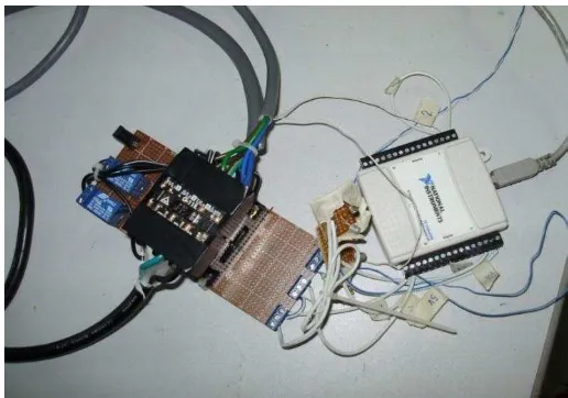
The power supply module plays the role of supplying the entire system with required power. The input power to the system is an AC voltage 240 V, 50 Hz. This input power supply is purposely to control the heater and stir-rer. The switching of the power supply is controlled by using interface device from server computer. The inter-face circuit is shown in Fig. 3.
) 6 ' 8
When 2 Pole Contactor is triggered, the heater will be switched on to heat up the liquid inside the tank. But when there is no signal from the server computer, the output from 2 Pole Contactor is in open circuit mode where the heater is switched off. Fig. 4 shows the sche-matic diagram of the interface circuit.
) > / 4 ' 8
The temperature sensor used in this water bath sys-tem is RTD. The resistance in RTD would increase gradu-ally as the temperature increase. The usage of this sensor is suitable as the temperature range in this water bath system is between 0ºC to 100°C. Refer to Fig. 4 the RTD is connected to a voltage divider circuit and the output is connected to analog input on NI USB 6008 device.
Fig. 5 illustrates the National Instruments Driver used in
this project where it provides connection to eight analog
input (AI) channels, two analog output (AO) channels, 12 digital input/output (DIO) channels, and a 32-bit counter when using a full-speed USB interface [18]. These termin-al blocks provide 16 connections that use 16 AWG to 28 AWG wire. Figure 6 shows the overall interface circuit for the system.
) 0 @ ' 8 ' -' ./% 0112
Thermometer from Extech Easyview 10 is used to read the current temperature in degree Celsius. In this project, thermometer as shown in Fig. 7 is used to calibrate the temperature reading so that the exact temperature will be feed to the system.
) : !
Nowadays, water bath is widely used in industries, especially food processing. It is used for producing new liquid products such as milk drinks, chocolate drinks, etc. In addition, water bath is also popular equipment in
med-ical laboratories, where the temperature control of certain liquid is important. The water bath temperature is con-trolled using Fuzzy Logic control. An interactive Graphi-cal User Interface is developed to facilitate the users in controlling the system. Besides, a well developed input-output device is used to interface between the server computer and the plant itself.
Fig. 8 and Fig. 9 show the outer part and inner part of the water bath respectively. Besides having a stirrer, hea-ter and RTD sensor, it also consists of inlet and outlet valve to cater with the water flowing in and out of the water bath.
) 2 @ ( %
) A ' ( %
The water bath itself is made by aluminum with insu-lation. Since, this project dealing with hot water inside it; therefore it is a need to insulate the inner and outer part for safety purposes. The water bath is designed for 7 liter of water filling.
The second stage is to build the Fuzzy Logic Controller using LABVIEW software, where fuzzy set and rule base are applied. The RTD sensor, heater and stirrer in the sys-tem determine the input and output quantities of a fuzzy controller. Each quantity being measured provides infor-mation about the current process state. Fig. 10 shows the block diagram of the water bath temperature control sys-tem. It describes how fuzzy controller takes part in con-trolling the temperature.
) ,1 % ( % !
8 /
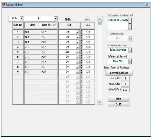
Every fuzzy logic system must have a rule base. The rule base is used to infer the actions that need to be taken based on the current conditions. Fig. 11 shows the rule base for the control system. From the Rulebase Editor front panel, the defuzzification method and inference method can be selected. In this case, Center of Gravity defuzzification and Max-min inference method are cho-sen.
) ,, ( % 8 3 %
The centre rule which is the steady-state rule can be writ-ten as follows:
IF Error in Temperature is about ZE1 AND the Derivative of Error is about ZE2 THEN the Change in Control Input is about ZEo
( IF e = ZE1 AND ∆e = ZE2 THEN ∆u = ZEo )
A rule can be written in triple form such as:
( ZE1, ZE2; ZEo )
A matrix of the rule base can be set up as shown in Fig. 11. The second and the third column are the antece-dents and the forth column in the matrix are the conse-quents.
A defuzzification technique used to give a crisp output value. It is required to produce the actual signal that the plant can use. Thus, the fuzzy output value needs to be defuzzified.
The output of the fuzzy controller is usually the change in the control signal. Equation (1) shows the ac-tual control signal to the plant.
u(k+1) = u(k) + ∆u(k) (1)
For centroid defuzzification, the value is given as (2),
(2) z* = [ Σ µc (z) . z ] / [ Σ µc (z) ] (2)
The front panel of the water-bath control system for this project is shown in Fig. 12. The desired temperature can be selected by key in the desired values. In addition, the current temperature can be monitored through the indicator shown. The response between the set point and process variable can be monitored in the waveform graph. While the block diagram of the overall process is depicted in Fig. 13.
) ,5 ) B ( % !
) ,6 % ( % !
8 /
3.3 Stage 3
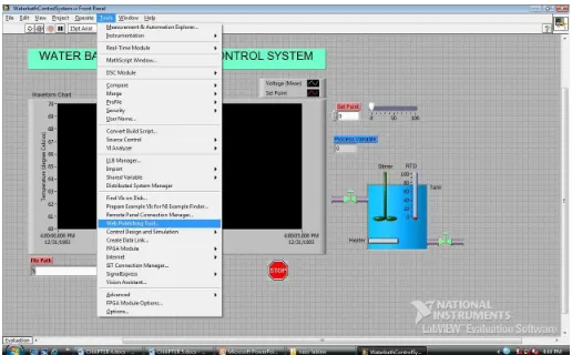
The final stage is to publish the GUI module onto the web for real-time remote control. Before the GUI is pub-lished on the web, there are a few steps that need to be taken. The LabVIEW Web Server need to be used to create HTML documents, publish front panel images on the Web, and embed VIs in a Web page. First Web Server must be enabled with the Web Publishing Tool as shown in Fig. 14. Furthermore, the VIs must be in memory before being published.
Fig. 14. Web Publishing Tool Setting.
In Web Publishing Tool, it will accomplish some tasks which are creating an HTML document and embed im-ages of the front panel in an HTML document (but cur-rently only Netscape browsers support animated images). From Fig. 15, Web Publishing Tool can also embed a VI that clients can view and control remotely, adding text above and below the embedded VI front panel image, place a border around an image or embedded VI, and preview the document.
) ,? &' & /
Last but not least, it can save the document to disk and finally enable the Web Server for publishing HTML documents and front panel images on the Web. This can be seen in Fig. 16. Fig. 17 shows the URL address that will be needed to access the page from a browser.
) ,0 ( B 4 4
) ,: .3$ # ( % /
their computer, except the block diagram executes on the server.
The server computer must first be configured before the students can view and control a front panel remotely using LabVIEW or a Web browser. By configuring the Web server, browser access to the server can be controlled and which front panels are visible remotely can be speci-fied. In addition, it also can set a time limit on how long a remote computer can control a Water Bath Temperature Control System when multiple students are waiting to control the water bath temperature control system.
Multiple students are allowed to connect simultane-ously to the same front panel, but only one student can control the front panel at a time. The user at the server computer can regain control of water bath temperature control system at any time. When the controller changes a value on the front panel, all student front panels reflect that change. However, students’ front panels do not re-flect all changes.
4 E
XPERIMENTALR
ESULTSThe water bath temperature control system can be mo-nitored and controlled remotely via internet. Any student can access to the server computer and the water bath temperature control system which are already setup in the lab, regardless of their geographical location, as long as they have computers, web browsers and internet con-nections. In addition, live experiment on the water bath temperature control system using Fuzzy controller is pub-lished in the website.
Based on the result that was obtained from the devel-op fuzzy logic controller using LABVIEW software, the fuzzy controller was able to identify the current tempera-ture and try to achieve the desired set point that set by user. All the data were collected and save automatically in Notepad. Then, the data were transferred in MATLAB software. By using the MATLAB software, all the useful data from Notepad were plot so that the waveform signal can be easily analyzed.
) ,2 ( ?1 8
The waveform signal when the set point was 50ºC is depicted in Fig. 18. The figure shows temperature versus number of data taken during the experiment. From the waveform, it can be seen that the initial temperature was
a room temperature which is 30°C. After the set point was set to 50°C, the fuzzy controller is trying to reach the set point and after 24 minutes, the desired temperature is achieved.
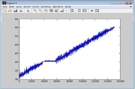
Fig. 19 shows the signal waveform when the process set point was 40ºC. After five minutes the system reaches its set point, then the user change the set point to 60ºC. From 40ºC to 60ºC, generally, it takes about 10 to 15 mi-nutes to the system to achieve its new set point.
) ,A ( >1 8
Set point of 70ºC and 80ºC were set, and the waveform is as depicted in Fig. 20. Initially the temperature inside the water bath was 60ºC. But after the set point is set to 70ºC, the fuzzy controller tries to reach 70ºC and it can be clearly seen that the readings is stagnant for a while after it achieves 70°C. Then, when the set point was changed to 80ºC, the fuzzy controller was then again tries to achieve it and it goes stagnant once the desired temperature is achieved.
Fig. 20. Waveform for setpoint 70oC.
This project can be further developed for better im-provement. First, in order to minimize the chattering, the voltage divider circuit can be upgraded by adding a ca-pacitor or an inductor. This can improve the signal wave-form to be less noise.
Next, we can develop and publish more experiments, namely PID control, Neuro-fuzzy controller and Neural-Network controller. Currently, we have Fuzzy Logic con-trol experiments in the website. Hence, more experiments on other controllers should be developed and the present experiments in the e-learning website can also be further improved.
Last of all, more virtual laboratories for other control systems should be developed and added into the e-learning virtual laboratory website. For instance, a.c. mo-tor speed control system and couple tank liquid level con-trol system. A more complete and various virtual labora-tories will promise a better virtual laboratory facility for (RTD), a heater and a stirrer. An interface system has also been mounted so that the water bath can be controlled through the server computer using the GUI module de-veloped.
An internet based GUI module environment of a wa-ter bath temperature control system has successfully been developed using LABVIEW software and published onto the web where it can be fully controlled using Fuzzy Log-ic Controller developed, and monitored by any user de-spite of their geographical locations, as long as they have computers with web browsers and internet connection.
A
CKNOWLEDGMENTThe authors would like to express sincere gratitude to Faculty of Electrical Engineering, Universiti Teknikal Ma-laysia Melaka (UTeM), MaMa-laysia for given the opportuni-ties on using the faciliopportuni-ties of equipment throughout this research activity.
R
EFERENCES[1] Euan Lindsay, Dikai Liu, Steve Murray and David Lowe, "Remote Laboratories in Engineering Education: Trends in Students' Perceptions", Proceedings of the 2007 AaeE Conference, Melbourne.
[2] V. Ramakrishnan, Y. Zhuang, S.Y. Hu, J.P. Chen, C.C. Ko, B.M. Chen and K.C. Tan, "Development of a Web-Based Laboratory for Control Experiments on a Coupled Tank Apparatus",
Proceedings of the 2000 American Control Conference, Vol. 6 pp. 4409 - 4413.
[3] C.C. Ko, B.M. Chen, S.H. Chen, V. Ramakrishnan, R. Chen, S.Y. Hu, Y. Zhuang, "A Large Scale Web-Based Virtual Oscilloscope
Laboratory Experiment", Enginering Science & Education Journal, in press.
[4] S.H. Chen, R. Chen, V. Ramakrishnan, S.Y. Hu, Y. Zhuang, C.C. Ko, B.M. Chen, "Development of Remote Laboratory Experimentation through Internet", Proceedings of the 1999 IEEE Hong Kong Symposium on Robotics and Control, Hong Kong, Volume II, pp.756 - 760, July 1999.
[5] Hartmut Ewald and George F. Page, "Performing Experiments by Remote Control Using the Internet", Global J. of Engineering Education, Vol. 4, No.3, Australia.
[6] Miladin Stefanovic, Vladimir Cvijetkovic, Milan Matijevic and Visnja Simic' "A LabVIEW-Based Remote Laboratory Experiments for Control Engineering Education", 2009 Wiley Periodicals, Inc.
[7] Sanjib Das, L. N. Sharma and A. K. Gogoi, "Remote Communication Engineering through Internet", International Journal on Online Engineering, 2006.
[8] Ralph M. Ford, Jonathan Bondzie, and Paul Kitcho, "Java Applets for Microelectronics Education," IEEE Trans. on Education, vol. 44, No. 2, May 2001.
[9] J. Sanchez, S. Dormido, R. Pastor, F. Morilla, "A Java/Matlab-Based Environment for Remote Controlled System Laboratories: Illustrated with an Inverted Pendulum," IEEE Trans. on Education, vol.47, No.3, pp.321-329, August 2004.
[10] Nitin Swamy, Ognjen Kuljaca, and Frank L. Lewis, "Internet-Based Educational Control Systems Lab Using NetMeeting," IEEE Trans. on Education, vol. 45, No. 2, pp. 145-151, May 2002.
[11] Kevin M. Passino and Stephen Yurkovich, “Fuzzy Control,” 1998 Addison Wesley Longman, Inc.
[12] L. A. Zadeh. Fuzzy sets. Informat. Control, 8:338–353, 1965.
[13] L. A. Zadeh. Outline of a new approach to the analysis of complex systems and decision processes. IEEE Trans. on Systems, Man, and Cybernetics, 3(1):28–44, 1973.
Mohd Farriz Basar is a member of IEEE since 2009. He received his B. Eng. Degree and M. Eng. Degree in Electrical Power from Universiti Teknologi Malaysia (UTM), Johor, Malaysia in 2002 and 2009, respectively. Since 2005, he is lecturer in Faculty of Engineer-ing Technology at Universiti Teknikal Malaysia Melaka (UTeM), Ma-laysia. He is currently PhD student in Solar Energy Research Insti-tute in UKM, Malaysia. He active in innovation exhibition and compe-tition and he has won gold medal in Geneva, Switzerland; in Seoul, Korea and in Kuala Lumpur, Malaysia. His research interests include the field of control system, power electronics, renewable energy technology and applications.