EffEct of Soot ParticlE DiamEtEr to Soot
movEmEnt in DiESEl EnginE
M.H Hanai1, W.m.f. Wan mahmood2, m.Z abdul manaf 1, S. Zakaria 1, m.n.a Saadun1
1Faculty of Mechanical Engineering,Universiti Teknikal Malaysia Melaka,
Hang Tuah Jaya, 76100 Durian Tunggal,Melaka
2Department of Mechanical and Materials Engineering,
Faculty Engineering and Built Engineering, Universiti Kebangsaan Malaysia, Bangi
ABSTRACT
Soot is one of the end product produced from the combustion of diesel engine. It can adversely afect the performance of the engine. It can cause the lubricant oil to be dirty thus increase its viscosity. These will results to frequent change of lubricant oil. Therefore, the focus of this study is related to the mechanism soot particles movement during the combustion process in the cylinder of diesel engine. The study of the path movement of soot particles from the initial position where it was formed to the last position was carried out. To analyze their movements, the data formation of soot particles was obtained through the simulation of combustion engine using Kiva-3V sotware which was used in previous investigation. The data that were obtained from the Kiva-3v simulation were velocity vectors of the soot, fuel, temperature, pressure and others. This data is used in the MATLAB routine to calculate the location of soot particles in the combustion chamber. Mathematics algorithm which is used in the MATLAB routine is trilinear interpolation and 4th order of Runge Kuta. In this study, the inluence of soot particles diameter with diferent angular (θ) is included in the calculation to determine its movement. Results from this study shows that if the size of soot particles is bigger, the probability of the movement of soot particles to the combustion chamber wall is high thus contaminating the lubricant oil.
KEYWORDS: Soot, Kiva-3V sotware and drag force.
1.0 introDUction
In recent decades, diesel engine is among an alternative power
source have been widely used for cars due to the eiciency and
economically (Lloyd, 2001). In the European Union, diesel engine cars
have surpassed the market performance of gasoline cars. Besides that, more than half (53%) of the European Union using diesel engine in a new car market share in 2007 (Mahmood, 2011). This rapid growth is because of advantages of modern high-speed diesel engine in terms of fuel economy, remarkable low-end torque and overall performance (Mahmood, 2011). Despite of these advantages, diesel engine has its drawbacks especially from an environmental perspective. During combustion, diesel engines release dangerous and harmful substances
including particulate mater (soot), toxic metals, nitrogen oxides that form ozone and nitrate particulate mater, volatile organic compounds, carbon monoxide (CO), carbon dioxide (CO2), and variety of toxic
metals and gases such as formaldehyde, acrolein, and polycyclic
aromatic hydrocarbons (PAH). In 1994, the limit of particulate mater
emission that coming out from heavy duty of diesel engine is (0.1 g/bhp. hr) and become stricter and tighter in the future (Abraham et al., 1996).
On the other hand, Clean Air Act stated that emissions from diesel engine contain 40 hazardous air pollutants and known as carcinogen
(California Air Resources Board, 2000). Despite of environmental
perspective, emission of diesel engine like soot also causes bad efect to
the engine itself.
Particulate mater contains solid soot particles which will contaminate
the lubricant oil, thus viscosity of the lubricant oil increases. Subsequently the walls of the combustion chamber will not be adequately coated which will increase its wear (Mahmood, 2011). Besides that, when the viscosity of the lubricant oil increases, the interval between oil changes will also increase (Mahmood, 2011). The wear mechanism due to the soot is still not fully understood, therefore fundamental study about this area is needed. Previous researchers investigated on soot distribution in a diesel engine by using the CFD
sotware, Kiva-3v (Abraham et al., 1996). (Hong et al., 2005) carried out a soot particle size prediction along its path using combination
of Hiroyasu’s soot formation and Nagle and Strickland-Constable
soot oxidation rate expression. Meanwhile, (Seykens et al, 2009) also
developed a model for soot formation process in diesel engine which
follows the conceptual view of diesel spray combustion. On the other hand, this model uses zero-dimensional approach, which makes the model eicient and suitable as simulation tool.
According to (Suhre and Foster, 1992), in order to indentify and understand soot formation, wall deposition mechanisms are important
to be explored. The wall deposition mechanisms are electrophoresis,
mechanism. This study is supported by (Rosner et al, 1991). Besides that, (Rosner et al, 1991) stated that to determine soot movement, it is essential to understand some force acts to the particles like drag, electrostatic,
gravitational, acoustic, difusiophoretic and thermophoretic Besides
that, (Mahmood, 2011). Focusing more on analysis of soot path in the diesel engine. This study investigated soot particle movement in diesel engine by considering crank angle and applying in MATLAB routine. Soot formation that had been developed was not included wall deposition mechanisms into consideration (Mahmood, 2011). Besides
simulation, some researchers did the study by experimental such as
(Ping, 2003) and (Mancaruso, 2012). (Mancaruso, 2012) designed and developed an optical engine to investigate the combustion process starting from fuel injection to complete combustion. This study only focusing on combustion energy but not towards soot formation.
Ping and Seitzman (Ping, 2003) focusing on measurement of soot
concentration. By using Laser Induced Incandescence (LII), soot particle reacts with the high power laser and absorbs the laser heat. Subsequently the incandescence of soot increases. Even though there are numerous study towards soot formation and combustion process
but the study towards soot concentration experimentally in a diesel
engine is less numerous.
Therefore, the purpose of this proposed research is to investigate soot movement at a certain crank angle in combustion chamber. In this
study, the inluence of soot particles diameter with diferent angular (θ) included in the calculation to determine its movement. This investigation represents a irst step towards tracking the soot movement path and evolution of particles from nucleation to inal mass and form,
and to allow future development in order to increase the performance of diesel engine. Furthermore the diesel engines have potential to be used as hybrid vehicles to achieve lower emission target in the future. In addition, this study is aligned with government policy such as Malaysia National Automotive Policy (NAP) which promotes green technology that targeted by 2020, 10% of all cars in Malaysia should be of electric and electric hybrid vehicles (Sustainable Mobility, 2011).
2.0 mEtHoDologY
This study focus on simulation using MATLAB sotware based on
the soot, fuel, temperature, pressure and others (Mahmood, 2011). The
engine has a bowl-in-piston and lat cylinder head face coniguration,
with a seven-hole injector installed vertically and centrally. The
schematic diagram for crown piston coniguration is shown in Figure 1.
Figure 1. Crown piston Configuration
Cylinder wall
Piston Crown
Figure 1. Crown piston Coniguration
In Kiva-3V there are two method to determined the formation of soot in a combustion chamber, which is individual tracking and cumulative tracking. This studies focusing on the individual tracking. The starting location of soot can be determined by considering it the velocity same
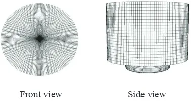
as that particular low. The combustion chamber mesh is shown in two
ways view (side and top) as in Figure 2.
Front view Side view
Figure 2. Meshing Model of Combustion Chamber
The simulations were carried out for the combustion system of a 4
valve DI diesel engine from inlet valve closing (IVC) to exhaust valve opening (EVO). The speciications of the engine are bore × stroke: 86.0 ×
86.0 mm, squish height: 1.297140330 mm, compression ratio: 18.2:1 and
displacement: 500 cm3, speed: 2500rpm. The details of the speciication of engine and mesh speciication are shown in Table 1 and Table 2
Table 1. Speciications of the Engine
Parameters Specifications
Engine Type 4 valve DI diesel
Bore × Stroke 86.0 × 86.0 mm
Squish height 1.297140330 mm
Compression Ratio 18.2:1
is the force of drag, ρ is the density of the fluid, v is the velocity of the object relative
ting coordinate in radial (rho), angular (θ)
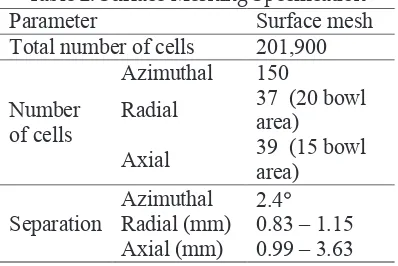
Table 2. Surface Meshing Speciication
Parameter Surface mesh
Total number of cells 201,900
Number
is the force of drag, ρ is the density of the fluid, v is the velocity of the object relative
ting coordinate in radial (rho), angular (θ)
The soot movement starting from its formation which is ater combustion process until the exhaust valve is open can be predicted by using numerical method. Euler method or also known as irst stage of Runge-Kuta method is an easy way to calculate and determine the
soot location. This method takes velocity at a certain location as soot’s velocity, and considered distance traveled by the soots. In order to
get an accurate value, higher stage of the Runge - Kuta method can be used. And as for this study 4th Stage of Runge-Kuta is used to calculate the soot's location. On top of that, to investigate soot velocity
at every condition trilinear interpolation method is used. In this study, the drag force equation is included in the simulation to determine soot movement. The drag force equation is
is the force of drag, ρ is the density of the fluid, v is the velocity of the object relative
ting coordinate in radial (rho), angular (θ) (1)
is the force of drag, ρ is the density of the fluid, v is the velocity of the object relative
ting coordinate in radial (rho), angular (θ)
Fd is the force of drag, ρ is the density of the luid, v is the velocity of the
object relative to the luid, A is the area and C
paths have been studied by considering reasonable crank angle. Data from the simulation is used in MATLAB routine to calculate and identify the soot location. In present paper the reasonable crank angle that is investigated in is at 8° ATDC. 8° ATDC is the intermediate of fuel injection which contains soot particle moves towards the bowl wall. There are a few assumptions done to run the MATLAB routine. Some of the mechanisms are reaction such as thermophoresis, newton respiration, and electrophoresis are neglected. In addition, the soot will
not relect if collided with the combustion chamber wall, instead it will
stick to the combustion chamber (Mahmood, 2011).
The locations which are considered in this studies: a) Rho=1.8cm, θ=15º and z=8.8cm, b) Rho=1.8cm, θ=25º and z=8.8cm and c) Rho=1.8cm, θ=45º and z=8.8cm. MATLAB routine will run at 8º ATDC of crank angle by using diferent diameter size of soot which are 300nm, 3000nm,
5000nm, 20000nm, 30000nm and 40000nm. Data from the simulation is tabulated in graph as shown in the results below, where by the front view and side view of the combustion chamber is displayed. The colors
show the diferent type of soot diameter. This study focusing on the inluence of soot particles diameter with diferent angular (θ) to the
soot particle movement path in the cylinder.
3.0 rESUlt anD DiScUSSion
The results of MATLAB routine show that soot movement in the diesel
are diferent based on diameter of soot particle. In Figure 4, Figure 5 and Figure 6 show 2 parts of pictures. At let side is respectively top
view and right side is side view of a half of combustion chamber of diesel engine. Sensitivity of soot particle location, starting point within
each zone in radial (rho), angular (θ) and axial direction (z) should be identiied irst. This studies consider three part of location which are
a) Rho=1.8cm, θ=25º and z=8.8cm, b) Rho=1.8cm, θ=45º and
z=8.8cm. From the result, it was found that most of the soot particles
move up and then move down when piston moves down.
It can be observed in Figure 3, that big size of soot particle has high tendency to go near to cylinder wall than the small size. Most of
the soot particles move in anti-clock wise motion and go near to the cylinder wall which is within 2mm distance. Besides that, it was found that when the diameter is 300nm, 3000nm and 5000nm the soot particle paths are not avaible in the graph. It is because soot particles follow the
ISSN: 2180-3811 Vol. 4 No. 1 June 2013 91
a) Rho=1.8cm, θ=15º and z=8.8cm
Soot movement during rho=1.8cm, θ=15º and z=8.8cm
the parameter of angular (θ), is different. In addition ,it can be seen that an increase of
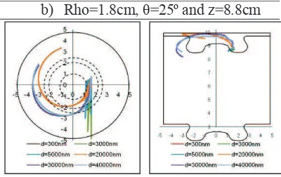
θ=25º and z=8.8cm
Soot movement during=1.8cm, θ=25º and z=8.8cm Figure 3. Soot movement during rho=1.8cm, θ=15º and z=8.8cm
Soot particle in Figure 4 are observed to behave almost similar to
Figure 1 eventhough the parameter of angular (θ), is diferent. In addition ,it can be seen that an increase of soot particle size, decreases
possibility of soot particle to move closer to the cylinder wall. It can also be observed that most of soot path were moved radially inwards,
and axially upwards. This is due to the fuel jet. The efect of fuel jet to the bulk luid plays a big role in order to move soot particle into squish
region (Mahmood, 2011).
Rho=1.8cm, θ=15º and z=8.8cm
Soot movement during rho=1.8cm, θ=15º and z=8.8cm
the parameter of angular (θ), is different. In addition ,it can be seen that an increase of
b) Rho=1.8cm, θ=25º and z=8.8cm
Soot movement during=1.8cm, θ=25º and z=8.8cm Figure 4. Soot movement during=1.8cm, θ=25º and z=8.8cm
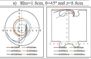
It can be also seen in Figure 5, the bigger size of soot particle goes easier near to the cylinder wall than small size of soot particle. Soot
a) Rho=1.8cm, θ=45º and z=8.8cm
Soot movement during rho=1.8cm, θ=45º and z=8.8cm
–
Figure 5. Soot movement during rho=1.8cm, θ=45º and z=8.8cm
4.0 conclUSion
In order to reduce lubricant oil contamination is to minimize the
transfer of soot particles to the cylinder wall. By understanding the movement path of soot particle in diesel engine, measures to reduce
soot particle movement towards the cylinder wall can be identiied.
Most of the bigger soot particles move upwards and anti-clockwise motion approaching the cylinder wall. Soot particle movement in a diesel engine depends on the diameter of the soot particle. Small
size of soot particle has low possibility to go the cylinder wall. The modiication of the bowl, piston shape and spray angle is expected to
reduce the possibilities of the soot particle moving towards the cylinder wall. This will be investigated further in the future.
5.0 acKnoWlEDgEmEnt
The authors would like to acknowledge Universiti Teknikal Malaysia Melaka (UTeM) PJP/2012/FKM(8A)/S01082 and Universiti Kebangsaan Malaysia (UKM) through GGPM-2011-055 Research Grant for supporting and funding these research activities.
6.0 rEfErEncES
Abraham, J.,Thermophoretic Efects on Soot Distribution in a Direct –Injection Engine, SAE Technical Paper, 960320, 1996.
Hong, S., Wooldridge, M.S., Im, H.G., Assanis, D.N and Pitsch, H. Development and application of comprehensive soot model for 3D CFD reacting low studies in a diesel engine. Combustion and Flame,
2005. 143: p. 11-26.
Lloyd, A.C., Cackete, T.A. Diesel engines: environmental impact and control, Journal of the Air & Waste Management Association 51 (2001) 809e847. Mahmood, W. M. F. W. 2011. Computational Studies of Soot Paths to Cylinder
Wall Layers of a Direct Injection Diesel Engine. PhD Thesis Department
of Mechanical, Materials and Manufacturing Engineering 2011, The University of Notingham.
Mancaruso, E., Sequino, L. and Vaglieco, B.M. GTL and RME Combustion Analysis in a Transparent CI Engine by means of IR Digital Imaging.
Proceedings of Ecos 2012.
Ping, Y. and Seitzman, J.M, Soot concentration and velocity measurement in an acoustic burner, AIAA, 2003, 1014, 41th Aerospace Science meeting and exhibition.
Rosner, D.E. , Mackowski, D.W., Garcia, P. and Barra, Y. ”Size - and Structure - Insensitivity of the Thermophoretic Transport of Aggregated Soot Particles in Gases", Combustion Science and Technology, 1991, Vol. 80, pp. 87-101.
Seykens, X.L.J., Baert, R.S.G. Somers, L.M.T. and Willems, F.P.T. Experimental Validation of Extended NO and Soot Model for Advanced HD Diesel Engine Combustion, 2009 SAE International, 2009-01-0683.
Suhre, B.R. and Foster, D.E. In-cylinder soot deposition rates due to thermophoresis in a direct injection diesel engine. SAE Papers, 1992(921629).