Master of Science in Manufacturing Engineering
Faculty of Manufacturing Engineering
DEVELOPMENT OF MOBILE ROBOT AND
LOCALIZATION SYSTEM
Khairul Anuar Bin Juhari
DEVELOPMENT OF MOBILE ROBOT AND LOCALIZATION SYSTEM
KHAIRUL ANUAR BIN JUHARI
A thesis submitted
in fulfillment of the requirements for the degree ofMaster of Science in Manufacturing Engineering
Faculty of Manufacturing Engineering
UNIVERSITI TEKNIKAL MALAYSIA MELAKA
APPROVAL
I hereby declare that I have read this thesis and in my opinion this thesis is sufficient in
terms of scope and quality for the award of Master of Science in Manufacturing
Engineering.
Signature: ……….
Supervisor Name: ……….
DECLARATION
I declare that this thesis entitle “Development of Mobile Robot and Localization System”
is the result of my own research except as cited in the references. The thesis has not been
accepted for any degree and is not concurrently submitted in candidature of any other
degree.
Signature :
Name : Khairul Anuar Bin Juhari
DEDICATION
i ABSTRACT
ii ABSTRAK
Pada hari ini, robot bergerak sangat meluas digunakan di dalam ketenteraan dan awam untuk melaksanakan aktiviti yang berbahaya, kotor dan berisiko tinggi di mana manusia tidak mampu melaksanakan tugas tersebut. Robot bergerak pada asasnya mampu berfungsi dengan sensiri tanpa bantuan manusia dan boleh beroperasi di pelbagai kawasan dan boleh dibezakan melalui kelajuannya, jarak bacaan penderia dan kebolehan senjata. Oleh itu, objektif kajian ini melibatkan pembinaan robot bergerak di dalam bangunan dan mencipta algoritma bagi pergerakan robot. Kajian ini juga
menggunakan kaedah “Extended Kalman Filter” (EKF) bagi proses penetapan lokasi
robot. Proses bermula dengan pembinaan rekabentuk mekanikal di mana pemilihan tayar dan kaedah locomotif dipilih. Setelah itu, pembetulan ke atas penderia odometer
dijalankan dengan menggunakan kaedah “University of Massachusetts Benchmark”
(UMBmark). Sebagai sebahagian daripada penglibatan terus terhadap kajian ini, kaedah
“Circular benchmark” (CBMark) telah diperkenalkan. Kaedah CBmark ini akan
meningkatkan ketepatan bacaan kelajuan motor dengan menambahbaik bacaan kelajuan pada enkoder motor. Setelah itu, algoritma bagi robot bergerak dicipta dengan
menggunakan kaedah “Extended Kalman Filter” (EKF). Kemudian, algoritma ini diuji
iii
ACKNOWLEDGEMENTS
First and foremost, I would like to take this opportunity to express my sincere acknowledgement to my supervisor Associate Professor Dr. Mohd Rizal Bin Salleh from the Faculty of Manufacturing Engineering Universiti Teknikal Malaysia Melaka (UTeM) for her essential supervision, support and encouragement towards the completion of this thesis.
I would also like to express my greatest gratitude to Mr.Mohd Nazrin Muhammad from the Faculty of Manufacturing Engineering Universiti Teknikal Malaysia Melaka (UTeM), co-supervisor of this project for his advice and suggestions in evaluation of the dessertation and technical support.
Particularly, I would also like to express my deepest gratitude to Mr. Shariman Bin Abdullah the lecturer from Robotic and Automation department of Faculty of Manufacturing Engineering, for the assistance and efforts in all the lab and analysis works.
iv
1.1 Introduction to mobile robot 1
1.2 Problem statements 3
2.2.7 Translational error and rotational error of mobile robot 20 2.2.8 Odometry calibration using offline method 22
2.2.9 Tuning the encoder 22
2.2.10 Positioning error and modelling 23
2.3 Process and controls 26
2.3.1 Closed loop control 27
2.3.2 Operating encoder with microcontroller 28 2.4 Ultrasonic range sensor for localization 28 2.4.1 Using multiple ultrasonic sensor simultaneously 29
2.5 Kinematics modeling for mobile robot 30
2.6 Mobile robot localization system 34
2.6.1 Extended Kalman Filter (EKF) localization 35
2.7 Conclusions 36
3. RESEARCH METHODOLOGY 37
3.1 Building the mobile robot 37
3.2 Encoder calibration proses 40
v
3.4 Design mobile robot localization algorithm 51
3.4.1 Prediction stage 52
3.4.2 Observation stage 53
3.4.3 Measurement prediction 55
3.4.4 Matching between predicted and observed 57
3.5 Playing field for mobile robot 59
3.6 Validating algorithm via simulations 60
3.7 Validating algorithm via hardware experiments 63
3.7.1 Experimental setup 65
3.8 Conclusions 66
4. RESULT AND DISCUSSION 67
4.1 Reiteration project objectives 67
4.2 Verification simulation results 67
4.3 Experimental results - Hardware 71
4.4 Validate performance between simulation and hardware results 73
4.5 Summary 76
5. SUMMARY, CONCLUSION AND RECOMMENDATIONS 77
FOR FUTURE RESEARCH
5.1 Conclusion 77
5.2 Recommendations for future works 78
REFERENCE/BIBLIOGRAPHY 79
vi
LIST OF TABLES
TABLE TITLE PAGE
3.1 Technical specifications of Direct Current (DC) geared motor. 39
3.2 Hardware changes and corrections 43
3.3 Encoder count for 1 revolution of wheel before calibrate 45
3.4 Encoder data count for 1 revolution of wheel after calibrated 47
3.5 Results of motor speed before and after using CBMark method 51
4.1 Collective data results for Case Study 1 69
4.2 Collective data results for Case Study 2 71
4.3 Hardware experiment results for Case Study 1 72
4.4 Hardware experiment results for Case Study 2 72
vii
LIST OF FIGURES
FIGURE TITLE PAGE
1.0 The blind man 2
1.1 Complete configuration of human-robot interface 3
2.1 Discrete probability distribution of vertex 7
2.2 Reflection process for ultrasonic sensor 8
2.3 Infinite plane based on HNF 9
2.8(b) A 3D image built by ultrasonic sensor 13
2.9 Pittman DC geared motor 15
2.10 The 3 wheels differential drive mobile robot 16
2.11(a) Quadrature encoder system 17
2.11(b) Quadrature encoder signal 17
2.12 Translational errors for mobile robot 21
2.13(a) 21
2.13(b) 21
2.14 Mobile robot distance travel data 23
2.15(a) Type A error in clockwise direction 24
2.15(b) Type B error in counter clockwise direction 24
2.16 PIC18F2331 microcontroller 26
2.17 Simple closed loop DC motor control systems 27
2.18 Mobile robot with multiple ultrasonic sensors 30
viii
2.20 Movement of differential drive mobile robot 32
2.21 Two independent driver wheels with single free wheel in front 33
2.22 Differential drive mobile robot kinematics 33
2.23 EKF for mobile robot localization 35
3.1 Mobile robot base 38
3.2 Flowchart process of building the mechanical hardware of mobile robot 37
3.3 The complete mobile robot 38
3.4 A3 paper with 2.5x2.5mm grid 40
3.5 Laser pointed to the ground 41
3.6 Encoder tuning process 42
3.7 Systematic errors before using UMBmark method 42
3.8 Systematic errors after using UMBmark method 43
3.9 Test track for CBMark method 44
3.10 Graph of encoder count versus number of trial 48
3.11 Diagram of speed tuning using CBmark method 49
3.12 Results of CBmark method 50
3.13 The playing field 51
3.14 Mobile robot localization flow process 52
3.15 Prediction of the mobile robot position 53
3.16 Line feature extraction form ultrasonic sensor 54
3.17 Detected entities by the mobile robot 56
3.23 Mobile robot is placed at the corner side with artificial landmark 63
3.24(a) 64
3.24(b) 64
3.24(c) 64
3.24(d) 64
ix
4.2 Case Study 1 simulation result 68
4.3 Case Study 2 simulation layout 70
4.4 Case Study 2 simulation result 70
4.5 Case Study 1 performance chart 73
x
LIST OF APPENDICES
APPENDIX TITLE PAGE
xi
Ecount - Encoder count per revolution of motor
Eencoder - Encoder resolution given by manufacturer
Nratio - Motor gearhead ratio given by manufacturer
D(diameter) - Diameter of wheel
Dtravel(distance travel) - Travel distance of wheel for one rotation
S(desired speed) - Actual motor speed
. ; / c g cw ccw
x - Center of gravity of x-axis for mobile robot
. ; / c g cw ccw
y - Center of gravity of y-axis for mobile robot
. , c g cw
r - Absolute offset of center gravity for clockwise direction
. , c g ccw
r - Absolute offset of center gravity for counter clockwise direction
j INt
- New position predictedbased on Extended Kalman Filter (EKF)
j
H - Jacobian matrix
jT
xii ^
t
P - Correlation matrix
i t
R - Matrix of measurement error
j INt
- State update mobile robot position
i t
1 CHAPTER 1
INTRODUCTION
1.1 Introduction to mobile robot
Mobile robotics is a young field. It includes many engineering and science disciplines
from mechanical, electrical and electronics engineering to computer, cognitive and social
sciences. For example, AGV (Autonomous guided vehicle) robot autonomously delivers parts
between various assembly stations by following a special electrical guide wires installed in the
floor. Using these wires as a guideline, the mobile robot can autonomously navigate itself
from one place to another place.
In general, mobile robots consist of wheel or terrain known as a mobile mechanism
and also sensors that are integrated with a controller and it can be operated neither human nor
autonomous (Guivant, 2000). Additionally the system has fully automated way known as
localization and controlling its path according to prediction using mathematical method or
logics. In robotic applications, localization means the ability to determine position of a robot
in its frame of references and then to plan a path towards some goal locations (Guivant, 2000).
Furthermore, localization also consists of combinations of the three fundamentals
which are self-localization, path planning and map building. Self-localization means the
ability of a robot to locate its position in a global map, while path planning refers to the way a
robot makes its decision for its target and map building requires the robot to locate and mark
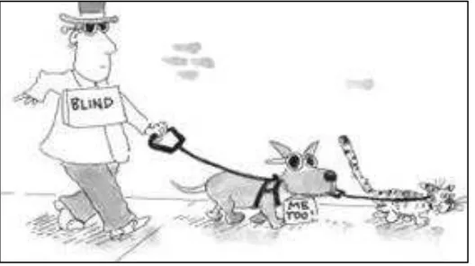
its position while it navigates. As shown in Figure 1.0 the blind man represents a mobile robot
2
a kitten. This represents the problem of navigation that can be translated to a 3 differences of
terminology; localization, position and navigation (Guivant, 2000). The localization will keep
questioning on how the robot locate itself in the environment given. The second situation
keeps asking about the position of the robot and the third situation is the navigation where the
robot plans its path that results in achieving the goal.
Figure 1.0 The blind man (Edwing, 1998).
Over the past 4000 years ago, these problems have been determined that it takes the
basic process of measuring distance, correlation and triangulation to successfully build and
managed the accuracy of Mediterranean area (Guivant, 2000).
In robotics applications, there are many methods that have been studied by previous
researchers. For example from Figure 1.1, Samperio (2010) developed a quadruped robot that
uses a visual localization to navigate in a dynamic environment. The robot would need to
locate a landmark within its surroundings and create an algorithm which determines any entity
3
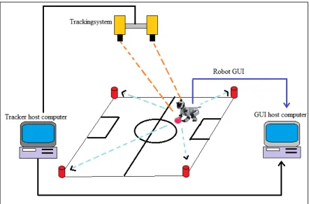
Figure 1.1 Complete configuration of human-robot interface (Samperio, 2010).
Jung (2011) had come out with procedures than can be used for robot to navigate
based on dead reckoning sensor and absolute position measurement. The method is called
University of Massachusetts Benchmark (UMBmark) method. This method can be used for
tuning the encoder and improve the encoder reading. The UMBmark use an offline method to
tune the encoder reading and it calibrated the encoder to improve the accuracy.
1.2 Problem statements
Conventionally, in order to use mobile robot in industries, manufacturers have to take
many considerations into account in planning the layout for the robot to follow especially
4
valuable spaces, in the other words the space that could be used for other machines must be
kept clear to make a way for the mobile robot path. This means, conventional path of the
mobile robot are planned based on the availability of spaces that the robot could move and not
robust. A fixed sensor such as one sensor for one program of the robot also may cause the
limitations to the robot. Fix sensor in this context refer to the dead reckoning sensor such as an
encoder and other positioning sensor which can only give one reading at a certain time. For
example, a mobile robot uses line following sensor to move according to the path given and
the sensor only detect the line to navigate. If there are any changes on layout, the engineer has
to reprogram the mobile robot and as a result, a delay in time will occur. In order to encounter
this problem, a type of mobile robot that has a robust system is suggested. The mobile robot
should have the ability to track the changes of its environment while it’s moving. This requires
the capability of navigation and localization.
1.3 Objectives
The objectives of this project are listed as follows:
To design and fabricate a mobile robot.
To develop the localization system of mobile robot based on Extended Kalman Filter
(EKF) method.
5 1.4 Scope of limitations
In order to achieve the objective, there are a few limitations that need to be considered. These
limitations are as listed below,
The design phase of the mobile robot refers to the creation of the mechanical part of
the robot and not using any advanced machine to fabricate.
Robot will navigate autonomously in predefined area of playing field and filled with
artificial landmarks.
Localization results are based on indoor applications only and tested on a hard surface
floor to minimize the errors especially the trajectory errors. The robot also designed to
be used in indoor environment only with standard flat surface floor.
Maximum speed of the robot has been limited 50 rpm (round per minutes) to reduce
unattended errors due to low cost sensors and the motor gear reduction ratio. The
operation of the robot also limited to 30 minutes for a single operation due to the
limited current supplied from the battery to the robot electronic control and motors.
Another issues on global references frame also been countered and all positions
estimations and prediction level of percentage is less than the actual result due to the
manufacturer technical specifications.
All this limitations has been set for future references and at the end of this research, the results
6 CHAPTER 2
LITERATURE REVIEW
2.1 Background of mobile robot
Nowadays, a desirable mobile robot will be more sophisticated and automated due to
the rapid development in science and machines technologies. Mobile robot is a robotic
platform that is being used as an extension of human capability such as carrying a heavy load,
and exploration. This type of robot is generally capable of operating outdoors and over a wide
variety of terrain, functioning in place of humans and controlling using teleoperatedly or
autonomously. With the help of sensors and algorithm, the mobile robot can explore the
unknown terrain or discoverable terrain itself.
Sensors can provide some limited feedback such as distance travel, position and
location to the robot so it can do its job. Maxim (2004) indicates that, in order for the robot to
navigate through the environment from point to point, the robot should be able to choose an
action to maximize its chances of getting to its goal with the help of sensors. This can be done
using probabilistic navigation. Maxim (2004) also indicates two methods in determining the
probabilities which are devided into two stages, stage one as planning and stage two as
navigation. By assuming the specified goal the robot can be guided to the closest position.
This method uses a node lock systems where the nearest node will assist the robot to the goal
7
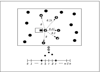
Figure 2.1 Discrete probability distribution of vertex (Maxim, 2004).
Figure 2.1 shows the system model that is used by Maxim (2004) is based on Markovian
method. This method will state the robot transition to depend only the current state and action.
As a result, by using this method, other robot which may not have to explore the entire space
can use the information for navigation. This solution is however inefficient since it is slow in
response to the navigation goal changes.
To compare with Guivant (2000), the basic navigation loop is based on dead reckoning
sensors that predict the frequency maneuver and low frequency absolute sensors that bounce
the positioning errors. By combining dead reckoning sensors and bearing sensors (laser range
sensor, ultrasonic sensor range sensor, etc), this land robot could obtain a reasonable
prediction of the vehicle trajectory (Guivant, 2000). Recently, ultrasonic sensor has been
widely used for most indoor applications but they are not adequate for most outdoor