UNIVERSITI TEKNIKAL MALAYSIA MELAKA
DEVELOPMENT OF PLC BASED NAVIGATION SYSTEM FOR
MOBILE ROBOT
This report submitted in accordance with requirement of the Universiti Teknikal Malaysia Melaka (UTeM) for the Bachelor Degree of Manufacturing Engineering
(Robotics and Automation) (Hons.)
by
SEHA BINTI MOHD SAFFAR B051110148
900924-02-6272
DECLARATION
I hereby, declared this report entitled “Development of PLC Based Navigation System for Mobile Robot” is the results of my own research except as cited in
references.
Signature : ………..
Author’s Name : SEHA BINTI MOHD SAFFAR
APPROVAL
This report is submitted to the Faculty of Manufacturing Engineering of UTeM as a partial fulfillment of the requirements for the degree of Bachelor of Manufacturing Engineering (Robotics and Automation) (Hons). The member of the supervisory committee is as follow:
……….
i
ABSTRAK
Sebuah mesin yang diprogramkan digelar robot mudah alih mempunyai kemahiran bergerak dalam mana-mana persekitaran yang ditetapkan. Robot mudah alih juga tidak tetap kepada satu lokasi fizikal seperti robot industri yang biasa. Kebanyakan robot mudah alih yang dicipta sebelum ini menggunakan sistem kawalan PID dan Fuzzy untuk mengawal pergerakan mereka. Walaupun PID dikenali sebagai sistem kawalan yang terbaik untuk robot mudah alih, kesukaran menggunakannya serta menulis program di dalamnya membawa perhatian untuk mengkaji system kawalan yang lebih mudah seperti PLC.
iii
ABSTRACT
v
DEDICATION
vi
ACKNOWLEDGEMENT
Bismillahirrahmanirrahim,
Alhamdulillah, thanks to Allah SWT, who with his willing giving me the opportunity to complete this Final Year Project (FYP).
Firstly, I would like to express my deepest gratitude to my project supervisor, Dr.Fairul Azni bin Jafar who had guided me to complete this project successfully. I would like to express an appreciation for his ideas, guidance, encouragement and professionally giving constant support in ensuring this project possible and run smoothly as per planning schedule.
I also truly grateful to those lecturers and staff in Faculty of Manufacturing Engineering, UTeM especially in Department if Robotics and Automation, that willing to help me in many ways. Sincerely thanks to them for their excellent corporation, supports and inspiration during this project.
x
CHAPTER 5 97
5.1 Conclusion 97
5.2 Future work (Recommendation) 98
REFERENCES 99
APPENDIX A 104
APPENDIX B 105
xi
LIST OF TABLE
4.1 Input assignment 49
4.2 Output assignment 49
4.3 Truth table for input and output 52
4.4 Error data recorded for 1st run 67
4.5 Error data recorded for 2nd run 69
4.6 Error data recorded for 3rd run 72
4.7 Error data recorded for 4th run 74
4.8 Error data recorded for 5th run 76
4.9 Data tabulation for 1st experiment 80
4.10 Data tabulation for 2nd experiment 83
4.11 Data tabulation for 3rd experiment 86
4.12 Data tabulation for 4th experiment 89
xiii
3.14 The picture shows the expected result for each line 44
xiv 4.13 Connectivity cable for PLC Keyence KV16T to desktop computer 63 4.14 The relationship of actual path and line graph for data analysis 65
4.15 The straight line path of the experiment 66
4.24 The actual line as illustrates in yellow box in line graph 73
4.25 Result of the 4th run 74
4.26 Line graph of error vs targeted path. 75
4.27 The actual picture where the mobile robot moved in straight line. 75
4.28 Result of the 5th run 76
4.29 Line graph of error vs targeted path. 77
4.30 The actual image where mobile robot exceeding line as illustrated 78 in previous figure.
4.31 The actual U-shape line to analyze mobile robot movement. 78 4.32 The 1st run of mobile robot movement on U-shape 79
4.33 Line graph of error vs targeted path. 81
4.34 Actual picture to show the turning of mobile robot that exceed 81 upper limit.
xv
4.36 Line graph of error vs targeted path. 84
4.37 The actual path of second turning point. 84
4.38 The 3rd run of mobile robot on U-shape 85
4.39 Line graph of error vs targeted path. 87
4.40 The actual turning point during 3rd run experiment. 87
4.41 The 4th run of mobile robot on U-shape line. 88
4.42 Line graph of error vs targeted path. 90
4.43 Yellow box indicates the accurate turned movement of mobile robot. 90
4.44 The 5th run of mobile robot on U-shape 91
4.45 Line graph of error vs targeted path. 93
xvi
LIST OF ABBREVIATIONS, SYMBOLS AND
NOMENCLATURE
AGV - Automated Guided Vehicle
CPU - Central Processing Unit
DC - Direct Current
FKP - Fakulti Kejuruteraan Pembuatan
FYP - Final Year Project
LED - Light Emitted Diode
PC - Personal Computer
PIC - Peripheral Interface Controller PID - Proportional-Integral-Derivative
PLC - Programmable Logic Controller
SFC - Sequential Functional Chart
SMS - Short Message Service
WMR - Wheeled Mobile Robot
1 are actually contributing more with their skills in helping human to complete much kind of jobs. In general robot can be classified into two categories which are fixed robot and mobile robot. While most of the fixed robots can be found in manufacturing environment, robot with mobility function gave a lot advantages in helping humans in environment such as agriculture land, hospital, hazardous field, household as well as manufacturing environment.
2
and are not fixed to one physical location as categorized as fixed robot. Mobile robot can be classified by a few characteristics which are: the environment; the device or tools they used to move.
In order for mobile robot to work successfully in human living environment, they need to have skills which allow them to perform tasks similar to the human being. One of the skills which could be considered as most important for mobile robot is navigation. Navigation is ability of the robot to move in an environment. There are many types of mobile robot navigation, example like:
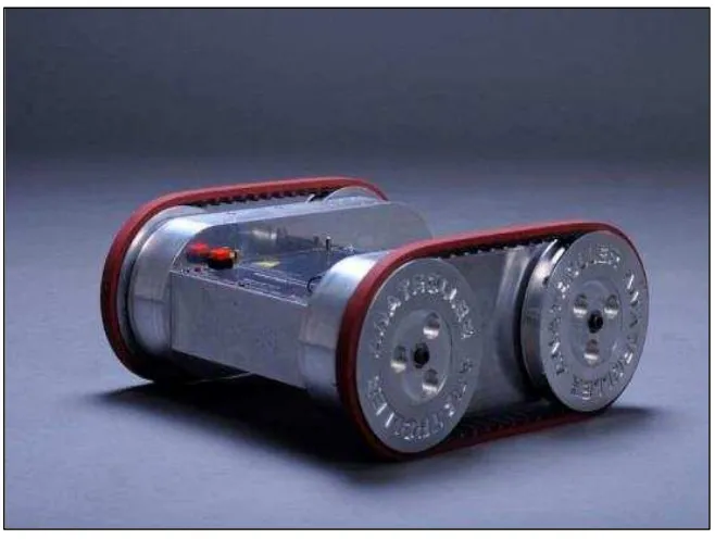
Manual remote, mobile robot is under control of a driver with joystick or other control devices. Example of ANATROLLER ARI-100 and ARI-50 as shown in Figure 1.1.
Figure 1.1: Mobile robot of ANATROLLER ARI-100.
(Source: < http://www.directindustry.com/prod/robotics-design-inc/robotic-crawlers-57161-1176337. >
3
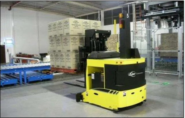
Line-following robots, as shown in Figure 1.2, Automated Guided Vehicles (AGVs) are the best example of mobile robot that used line following navigation system. They trail a visual line painted or embedded in the floor.
Autonomous guided robot, the robot knows at least some information about where it is and how to reach various goals.
1.2 Motivation
For centuries, the revolution in technology undoubtedly is the robot. Starting from dream of a man to be free of the drudgery of manual labor using automatic device until currently in 21st century where robot has been applied to almost all types of labor industries. Every day a growth of robot can be seen with increasing human like capabilities, such as recognizing objects and moving around independent of human control (Girme et al., 2007). Furthermore, there has been much interest on achieving educational and research goals by the use of mobile robots (Greenwald and Kopena, 2003). Thus, a low cost robot platform is commonly used and frequently controlled by some kind of microcontrollers PC with interface cards together with the growth of mobile robot. There are less mobile robots with industrial based system being
Figure 1.2 : Example of Automated Guided Vehicle.
(Source: <http://www.jbtc-agv.com/en/Solutions/Products/Forked-Automatic-Guided-Vehicles-AGVs. >
4
developed. Thus, it motivates to do a project in developing the types of mobile robot with a controller of Programmable Logic Controller (PLC).
1.3 Problem statement
There are two ways that can be used in mobile robot development. First way is to build up an embedded system, the second is to use ‘ready to use’ industrial components. Using Peripheral Interface Controller (PIC) as a microcontroller of mobile robot is a common application used by engineers or researchers in developing mobile robot. With embedded system where engineer can build their own system according to what they want and program it according to their hardware, thus it make PIC is much favorable among engineers. But, for some people who want a system hardware. Furthermore, PLC is very suitable for manufacturing industries because it’s more simple compare to PIC (e.g. C Language). But yet, it’s still very less mobile robot which used PLC as the navigation controller and it’s not impossible to create a simple and flexible mobile robot based on PLC navigation system.