UNIVERSITI TEKNIKAL MALAYSIA MELAKA
ANALYSIS ON CORNERING PERFORMANCE OF PLC BASED
MOBILE ROBOT NAVIGATION SYSTEM
This report submitted in accordance with requirement of the Universiti Teknikal Malaysia Melaka (UTeM) for Bachelor Degree of Manufacturing Engineering
(Robotic and Automation) with Honours.
by
NUR SABIHA BINTI HASBULLAH
B051110149
920105-03-5448
DECLARATION
I hereby, declared this report entitled “ Analysis Cornering Performance of Plc Based Mobile Robot Navigation System” is the results of my own research except as cited in references
Signature :
APPROVAL
This report is submitted to the Faculty of Manufacturing Engineering of UTeM as a partial fulfilment of the requirements for the Degree of Bachelor of Manufacturing Engineering (Robotics And automation) with Honours. The member of the supervisory committee is as follow:
ABSTRACT
Mobile robot is defined as a programmed machine that is skilled of movement in any controlled environment. They have capabilities to move around in their environments and are not fixed to one physical location as categorized as fixed robot. The example of mobile robot such as mobile robot navigation, mobile robot at the space and so on. Although the robot has been created with a good design and control, it still have a problem. The problem that always faced by the robot like, speed, program, sensor and also avoidance obstacles of the objects. Thus, it motivates to analysis the one of the problem of the mobile robot navigation system which is the problem during make a cornering.
ABSTRAK
Robot mudah alih ialah didefinisikan sebagai sebuah mesin diprogramkan yang mahir pergerakan di mana-mana persekitaran terkawal. Mereka mempunyai kebolehan bergerak-gerak dalam persekitaran mereka dan tidak ditetapkan bagi satu lokasi fizikal seperti yang dikategorikan sebagai robot tetap.
Contoh robot mudah alih seperti pelayaran robot mudah alih, robot mudah alih di ruang dan sebagainya. Walaupun robot telah mewujudkan dengan satu perancangan baik dan mengawal, ia masih lagi satu masalah. Masalah yang sering menghadapi oleh robot seperti kelajuan, sistem, penderia dan juga halangan-halangan pengelakan objek. Maka, ia mendorong kepada analisis salah satu masalah sistem pandu arah robot mudah alih yang merupakan masalah semasa membuat satu membelok
Untuk analisis projek, eksperimen pelayaran akan diuji di laluan bentuk u dan eksperimen akan berulang dengan tiga perkakasan berbeza. Keputusan eksperimen akan mewakili di graf supaya tahu prestasi takik keliling robot mudah alih.
DEDICATION
ACKNOWLEDGEMENT
In the name of ALLAH s.w.t, the most Gracious and most Merciful. thanks for giving me the strength and confidence to complete this Final Year Project (FYP). First of all, In this great opportunity, i wish to express my sincerest, appreciation and thousand thanks to my project supervisor, Dr.Fairul Azni bin Jafar who had guided me to complete this project successfully. I would like to express an appreciation for his ideas, guidance, encouragement and professionally giving constant support in ensuring this project possible and run smoothly as per planning schedule.
I also truly grateful to those lecturers and staff of the Faculty Manufacturing Engineering, UTeM that willing to help me in many ways. Sincerely thanks to them for their excellent corporation, supports and inspiration during this project.
4.7 Navigation experiments 52
4.8 Experiment requirement 53
4.9 Navigation experiments results 54
4.9.1 Transistor effect 54
4.9.2 For the distance between the sensor 4 cm with reverse action 58
4.9.3 For the distance between the sensor 3 cm with reverse action 62
4.9.4 The distance between the sensor 4 cm without reverse action 66
4.9.5 The distance between the sensor 3 cm without reverse action 70
4.10 Discussion 74
5. CONCLUSION AND RECOMMENDATION 75
5.1 Conclusion 75
5.2 Recommendation 76
REFERENCES 77
APPENDICES
A Gant Chart for FYP 1
LIST OF TABLES
4.1 Input task 35
4.2 Output task 35 4.3 Output task for program without reverse action. 36
4.4 Error data tabulation with transistor and without transistor 55
4.5 Error data recorded for first run, second run and third run 59
4.6 Error data recorded for first run, second run and third run 62
4.7 Distance between the sensor 4 cm 67
LIST OF FIGURES
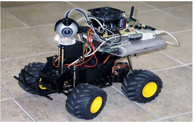
1.1 Mobile Robot of Vision System for Landmarks Detection 2
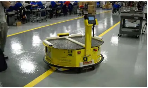
1.2 Example of Automated Guided Vehicle 3
2.1 Mobile robot line following prototype 11
2.2 Block diagram of how the line follower robot works 11
2.3 Robot path following (a) simulation (from top view) showing (b) small slip and (c) large slip 19
4.9 Plc programming before stimulation without reverse action 45
4.10 Push button activated 46
4.11 Left sensor activated 47
4.13 Left and right sensor activated. 49
4.14 Pin out connection between RJ11 and RS232 DB9 50
4.15 RS232 DB9 51
4.16 RJ11 51
4.17 Connectivity cable for PLC Keyence KV16T to desktop computer 51
4.18 Actual condition for u shape 53
4.19 Actual path for straight line 53
4.20 Line graph for data analysis 54
4.21 Line graph of error path VS experimental path 56 4.22 Actual path for navigation with transistor and without transistor 56
4.23 Error at 5 cm 57 4.35 Actual path for first run, second run and third run 63
4.36 Error at point 30cm 64
4.37 Error at point 65cm until 80cm 64
4.38 Error point at 20cm
4.39 Error point at 60cm 65
4.40 Error point at 50cm until 65cm 65
4.41 Actual path for first run, second run and third run 66 4.42 Graph analysis for first run, second run and third run 68
4.43 Error at point 35 cm 69
4.44 Error at point 75 cm 69
4.45 Error at point 55 cm 69
4.47 The graph analysis for first run, second run and third run 72
4.48 Navigation for first run with no error 72
4.49 Error at point 80cm and 85cm for second run 73
LIST OF ABBREVIATIONS
AGV - Automated Guided Vehicle FKP - Fakulti Kejuruteraan Pembuatan FYP - Final Year Project
WMR - Wheeled Mobile Robot GPS - Global Positioning System
CHAPTER 1
INTRODUCTION
This chapter will explain the background of the project, the details of the problem statement and motivation, the objectives, the scopes, report structure and the report configuration of the project entitled “Analysis on Cornering Performance of PLC Based Mobile Robot Navigation System”.
1.1Background
Mobile robot is a type of robot that has ability to move around and is not fixed at only one position. It can move from one position to other position depends on the physical geometry and environment. Mobile robot will acts like a human and can performed the human tasks.
In order for mobile robot to work successfully in human living environment, they need to have skills which allow them to perform tasks similar to the human being. One of the skills which could be considered as most important for mobile robot is navigation. Navigation is ability of the robot to move in an environment. There are various types of mobile robot navigation one of the examples like manual remote. This type of mobile robot is control by driver by using joystick or other control instruments.
representation is a massive important factor to the robot in a navigation system. The representations stated are the map of the environment and the capable to read the task. Those important tasks will encourage the precise result in navigation system. Mobile robot navigation systems have been creating as a function to navigate the position. This task will make human job become easier.
Figure 1.1: Mobile robot of vision system for landmarks detection. (Source: http://www.neurotechnology.com/robotics.html).
Navigation can be classified as a combination of three core competencies which are self-localisation, path planning, map-building and map interpretation. Definition of the navigation is comprised of three categories which are Global Navigation, Local Navigation, and Personal Navigation. These three categories have different ability to determine the position. Global navigation has the ability to determine the position of an absolute or map-referenced, and to move to the desired destination. While in Local Navigation, the ability to determine a position compared with objects either the objects is stationary or moving in the environment, and to interact with properly and Personal Navigation involving realizing the various parts that make up the self, in relation to each other and the object handle.
lasers. AGVs have expressed hallway or area where it is or where they can navigate. For the guidance to mobile robot move successfully in the line, the AGVs use magnetic tape, buried guide wires, or painted stripes that have been draw on the ground. These vehicles have some disadvantages which are not freely programmable and cannot change their path in response to external sensory input (e.g., obstacle avoidance). However, the interested reader may find a survey of guidance techniques for AGVs in (Everett, 1995).
Figure 1.2: Example of Automated Guided Vehicle.
(Source:http://news.thomasnet.com/fullstory/Intelligent-AGV-enhances-lean-manufacturing-environments-582126).
Navigation is achieved by any one of several ways, including by an action defined by buried inductive wires, there is horse riding paths magnetic or optical, or alternatively as inertial or laser guidance.
1.2 Motivation
For the revolution in technology undoubtedly is the robot. Every day a growth of robot can be seen with increasing human like capabilities, such as recognizing objects and moving around independent of human control (Girme et al. 2007). There are many types of mobile robot that have been developed today to perform human tasks. Although the robot has been created with a good design and control, it still has a problem. The problem that always faced by the robot like speed, system, sensor and also the obstacles avoidance. Thus, it motivates to analyze the problem of the mobile robot navigation system in order to produce a good navigation system for mobile robot.
Mobile robot navigation have been installed correctly with a proper fundamental system like speed, shape, and the most important one its can navigate the position with a right performance according to the manufacturer‟s specifications and its environment.
1.3 Problem statement
Previously, PLC based navigation system for mobile robot have been develop and successfully move on the line following. During the navigation, there is problem occurred at u shape path. The robot can move successfully during the straight path but facing some problem during making a cornering. During the cornering, the robot cannot follow the u shape line following and accidently move out of the line.
1.4 Objective
i. To analyze the cornering problem of a PLC based mobile robot navigation system.
1.5 Scope
The purpose of this project is to analyze the cornering performance of a PLC based mobile robot navigation system.
i. The analysis covers about the motion and the problems of the robot. This research work is not covers the safety of the robots. The experiment that will be conducted to be in indoor environment. The environment setup will be in a flat silver area at the manufacturing laboratory hall.
ii. The experiment will be conducted on the mobile robot navigation systems that have been developed by previous PSM project.
1.6 Report structure
Chapter 1 is the introduction of the project. Under this chapter, there have 6 subtitles which are the background of the project, motivation, problem statement, objectives, scope and report structure.
Chapter 2 is all about literature review. This chapter comprises information about the robot, landmark based navigation, line following robot and problems needs to face by the robot.
Chapter 3 describes a design process to achieve the project‟s objectives. It includes the overall project plan, overall methodology flow chart, and details explanation about methods to analysis the cornering performance of the robot.
CHAPTER 2
LITERATURE REVIEW
Before starts analyze the project, some articles re-examine from the internet and book ensure the information from that source can be in order to do a research and analyze the cornering problem of mobile robot. These articles will be use as the guideline in this research project. This chapter will summarise and stress on paper content, report and article related to this project. A few theories that have related to this project also will be discussed in this topic.
2.1 Overview of mobile robot
P.Lima et al. (2002) wrote that the term mobile robot is principally a platform with a hefty mobility within its environment such as air, land or even underwater. Mobile robot consists of functional characteristics such as a total mobility relative to environment, a certain level of autonomy which limited to human interaction and a perception ability in sensing and reacting in the environment.
Locomotion mechanisms are important things for the mobile robot to enable it to move in unlimited all over the environment. But there are several of possible methods to move, so the selection approach of the robot to locomotion is one of important factor for mobile robot design. By the experiments that have been done in laboratory, the robots have prove that it can walk, jump, run, slide, skate, swim, fly, and, also can made a rolling. Most of these locomotion mechanisms have been motivate by their biological counterparts. The design of autonomous mobile robots competent of smart movement and action involve an integration of much knowledge of
completed by humans due to limited abilities. Robot are known have the higher ability in doing repetitive works with constant performance, working in dangerous area which could danger human life and make the job faster with less rest time. According to Dudek and Jenkin (2000), a mobile robot is autonomous systems which have intelligent function of traversing a facade with natural or artificial obstacles. The chassis is providing with wheel or legs and possibly a manipulator setup mounted on the chassis for work piece operation, tool or special system. There are variety trepanned operations are perform based on a reprogrammed navigation strategy taking into account the current status of the environment.
The first mobile robot was created approximately 63 years ago beginning in 1950 when Grey Walter assumed to integrate these two cognitive operations, goal seeking and scanning, into en electronic „toy‟ that would simulate these most basic characteristics of animal and human behaviour (Walter, 2003). Thus, it resulted in creation of the first mobile which has three wheels and often described as turtle because of its shape. Walter named his robot as Elmer and Elsie also used to be called as Machine Speculatrix because it tendency to explore its environment.
2.2 Robot navigation
2.2.1 Landmark based navigation
Navigation based on autonomy robot landmark was widely used in manufacturing industry. Navigation strategy depends on identification and recognition of a distinctive environment display or an object either known a priori or extracted dynamically. This process is inherently difficult in practice due to noise in detector and change in real world. This process is indeed hard in practice because of the noise problem in sensors and changes in the real world.
reduce confusion by preparing visual feedback on the approval of a navigation results.
Landmarks are the geometrical features that a robot can detect from its sensory input. Landmarks can be variety of geometric shapes such as square, line and circle and they may contain an additional information (e.g., in the form of bar-codes). Landmarks are carefully selected in order to easy to recognize for example, there is must be contrast relative that is enough to all background. The characteristics of the landmarks must be known and stored in the robot‟s memory before a robot can use for navigate. The main function in localization is to identify the landmarks definitely and to measure the robot‟s position.
In summarize, there are a few characteristic of landmark based navigation which are, the distance and angle between the robot and the landmark are important thing is positioning accuracy. When the robot move further afield from the landmark, the navigation will become inaccurate. When the robot is nearby a landmark, a greater degree of accuracy will be created.
2.2.1.1 Natural landmarks